Table of Contents
Advertisement
GE
Measurement & Control
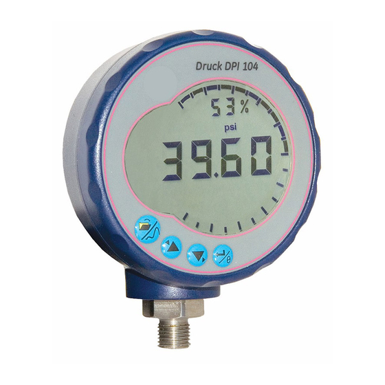
Druck DPI 104
Digital Pressure Indicator
User manual - K0394
© 2011 General Electric Company. All Rights Reserved. Specifications are subject to change without notice. GE is a
registered trademark of General Electric Company. Other company or product names mentioned in this document
may be trademarks or registered trademarks of their respective companies, which are not affiliated with GE.
99 Washington Street
Melrose, MA 02176
Phone 781-665-1400
Toll Free 1-800-517-8431
Visit us at www.TestEquipmentDepot.com
Advertisement
Table of Contents

Related Manuals for GE druck dpi 104


Summary of Contents for GE druck dpi 104
- Page 1 Digital Pressure Indicator User manual - K0394 © 2011 General Electric Company. All Rights Reserved. Specifications are subject to change without notice. GE is a registered trademark of General Electric Company. Other company or product names mentioned in this document...
- Page 2 A1.1 A1.2 A1.3 K0394 Issue 3...
-
Page 3: Table Of Contents
Table of Contents Table of Contents .......... 1 Maintenance ..........18 Replace the batteries ........18 Introduction ........... 2 Restore the original configuration ..... 18 Safety .............. 2 Calibration ..........18 Marks and symbols ..........2 Equipment and conditions ......19 To Start ............ -
Page 4: Introduction
Introduction The Druck DPI 104 is a digital pressure indicator that measures the pressure of liquid, gas or vapor and shows the pressure value on a liquid crystal display (LCD). It also has the Intelligent Digital Output Sensor (IDOS) technology to use data from a Universal Pressure Module (UPM). -
Page 5: To Start
To Start Key to figure A1 Table 1: Key to figure A1 (Instrument) Item Description 8-pin connector for external power supplies, RS232/UPM connections and signal input/output. • Power on button. • Menu mode: Press and hold to show the first menu option. To move down the menu structure, press repeatedly, or continue to press and hold. -
Page 6: Key To Figure A2 (Display)
Key to figure A2 Table 2: Key to figure A2 (Display) Item Description 5-digit main display. 2.5-digit percentage indicator (0-100% FSO). %FSO = [applied pressure/(FSOHigh—FSOLow)] * 100 20 segment analog dial in increments of 5% FSO (large division marks = 10% increments). %FSO = [applied pressure/(FSOHigh—FSOLow)] * 100 The units of measurement: kPa, MPa, kg/cm , psi, mbar, bar,... -
Page 7: Prepare The Instrument
Table 3: (Part of Table) Key to figure A3 Option Description Part No. 1S-04-0027: 8-pin connector for A1: item 1. Refer to Table 6. Part No. 182-190: DPI 104 high pressure adaptor (9/16 UNF to 3/8 BSP) for a PV212 hydraulic hand pump [range ≥ 1000 bar (15000 psi)]. - Page 8 Page 5 Menu Description Steps Result/Subsequent steps C0 (correct the zero offset value) ➤ C _ _ _ _ = Calibration: To continue, set the correct calibration C2 (do a two-point pressure calibration) ➤ access code = last four digits V2 (do a two-point voltage calibration), refer to of S/N.
-
Page 9: Installation
Installation This section shows how to install and connect the DPI 104. Warning: To prevent an explosion or fire, use only the GE specified battery and external supply. DPI 104 Battery Use the procedures in Table 4 to install or replace the battery. -
Page 10: Pressure Connections
Pressure connections CAUTION: Do not use the body of the DPI 104 to tighten the pressure connection, this can cause damage. Use the flat faces on the pressure connector to hold the body and tighten the pressure union. Use an applicable method to seal the pressure connections, and then tighten to the applicable torque (Figure 1 and Table 5). -
Page 11: External Power
Table 3, page 4 gives the optional accessories that use the connector. Note: Use only original parts supplied by the manufacturer. The RS232 interface makes a serial network of units (maximum: 99). Refer to menu operation, page 5. External power Recommendation For the following functions and operations use an external power supply :... - Page 12 Tare - Set-up and use Menu: Set this function to On (refer to menu operation, page 5). When this function is On, there are two options to set a tare value (tA): • Menu option: Set the menu “t On”, then set a tA value: A display A display 0 to 9, or -...
-
Page 13: Menu: Monitor Maximum/Minimum
Menu: Monitor Use this function to monitor the maximum and minimum pressure. maximum/minimum It uses the specified scan rate (refer to menu operation, page 5). Recommendation To save battery power use an external power supply. Maximum/minimum - Menu: Set function to On (refer to menu operation, page 5).To save Set-up and use battery power use an external power supply. -
Page 14: Menu: Calibration
The switch symbol and the value on the main display flash to give the switch condition and the switch pressure. Press To reset the monitor function. Menu: Calibration Refer to the menu operations section. Menu: Set low/high Use the alarm function to show when the pressure is not in the alarm specified limits for the system. -
Page 15: Menu: Supply Voltage Output (Vout)
Menu: Supply Use the Vout function to supply a voltage output (0.05 to 5 V) to an voltage output (Vout) external system. Two options are as follows: P-V: Vout is proportional to the pressure value on the display. US: User mode. Set a value in the Vout register (0 to 100%) to control an external pressure regulator. -
Page 16: Menu: Set Vout Scale Factor
Menu: Set Vout scale When the Vout function is set to P-V or US mode, the Vout scale factor factor becomes part of the Vout calculation (refer to menu operations). If the pressure ranges for the DPI 104 and the external pressure regulator are different, an applicable scale factor (0.01 to 9.99) must be set. -
Page 17: Menu: Set Scan Rate
Lock code - Set-up and Menu: Set to On (refer to menu operation, page 5). Use the steps that follow to set a new code. Lock Lock Digit = 0 or 9 Digit = 0 to 9 3. Complete the lock code, repeat steps 1 & 2 for each digit. 4. -
Page 18: Menu: Set Fso Low/High Registers
Menu: Set FSO Use the FSO low/high registers to set a different range for the low/high registers functions that follow: analog display, % indication, low/high alarm. Initially, these register values are set to the factory calibration values. Example: Calibrated range: 0.7 bar (10 psi) gauge. Selected units: mbar FSO low FSO high... -
Page 19: Software/Network Connections
Software/network External software can be used with the DPI 104 (Table 3 connections accessories A or D, page 4). If SiCal PRO (accessory D) is used, all the menu commands and display data are available. Note: To use SiCal PRO, it must have the serial number of each unit to be used with (DPI 104, IDOS UPM, PC6-IDOS). -
Page 20: Maintenance
Calibration Return the DPI 104 to the manufacturer or an approved service agent for calibration. Note: GE can provide a calibration service that is traceable to international standards. If using an alternative calibration facility, make sure that it uses these standards. -
Page 21: Equipment And Conditions
Equipment and To do an accurate calibration, requires: conditions • the calibration equipment specified in Table 10, below. • a stable temperature environment: 20 ±1°C (68 ±2°F). Table 10: Calibration equipment Function Calibration equipment Pressure An applicable pressure standard (primary or secondary) with a total uncertainty of 0.01% reading or better. - Page 22 C0 (Zero offset) The DPI 104 shows the following displays: 1. The calibration point to be used for C0. This value is only adjustable for an absolute type DPI 104 (Table 11, page 19). C0 - Gauge = 0000.0 C0 - Absolute C0 - Absolute 8 seconds 0 to 9...
- Page 23 5. Repeat steps 3. & 4. for each digit and for the decimal point. The value is ignored if it is not in the permitted limits (Table 11, page 19). This value is then used as the set point (SP) for point 1 on the subsequent displays.
- Page 24 V2 (two-point voltage Point 1 (P1) - The DPI 104 shows the following displays: calibration) 1. The calibration point to be used for V2 - Point 1. 8 seconds 0 to 9 After step 2, the DPI 104 sets Vout to 0.1 V. Correct the value (P1) to the value shown on the voltage calibrator.
-
Page 25: Specification
Specification General Display EN 61326-1 Electrical Safety EN 61010-1 Pressure Safety Pressure Equipment Directive - Class: Sound Engineering Practice (SEP). Power supply 9V, IEC 6LR61, ANSI/NEDA 1604 battery, OR use an external 12-24 Vdc 50mA supply. Environmental The DPI 104 is suitable for indoor use with the following conditions environmental requirements. -
Page 26: Pressure Measurement
Pressure measurement Range: gauge (g), absolute (a), Resolution Maximum Working Media sealed gauge (sg) Pressure (MWP) notes bar* psi* Type mbar (-0.7) 0 to 0.7 (-10.0) 0 to 10 0.01 0.001 0.77 11.2 (-1.0) 0 to 2.0 (-15.0) 0 to 30 g* or a 0.001 (-1.0) 0 to 7.0...