Table of Contents
Advertisement
Advertisement
Table of Contents

Related Manuals for ABB 7651


Summary of Contents for ABB 7651
- Page 1 Instruction Manual pH/ORP Electrode System IM/7650_8 7600 Series...
- Page 2 Cert. No. Q 05907 As a part of ABB, a world leader in process automation technology, we offer customers application expertise, service and support worldwide. EN 29001 (ISO 9001) We are committed to teamwork, high quality manufacturing, advanced technology and unrivalled service and support.
-
Page 3: Table Of Contents
3.1.2 Operating Pressure & Temperature ... 7 3.2 Installing the System ........7 6.3 Checking the Electrolyte Level ....... 16 3.2.1 Models 7651, 7652, 7660 and 7661 .. 7 6.4 Replacing Electrodes ........16 3.2.2 Model 7652 ........8 6.4.1 Measuring Electrodes ...... 16 3.2.3 Models 7654, 7655, 7656, 7664 and... -
Page 4: Introduction
This manual describes: 0. 0 00 uS/cm • Model 7651 – polypropylene with optional pipe and flange 0. 0 00 uS/cm fittings. Dual Cond. • Model 7660 – stainless steel, in-line flow system. -
Page 5: Checking The Code Number
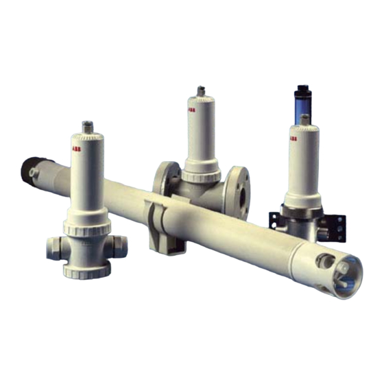
2 PREPARATION 2.1 Checking the Code Number – Fig. 2.1 A – 7651 (Polypropylene) B – 7660 (Stainless Steel) C – 7652 (Polypropylene) 7654 7664 E – 7661 (PVDF) D – Polypropylene 7655 PVDF 7665 7656 Fig. 2.1 System Types... -
Page 6: Identifying The Electrode Type
…2 PREPARATION 2.2 Identifying the Electrode Type – Fig. 2.2 and Table 2.1 A pH system is only as accurate as the electrodes used to make the measurement. To satisfy a wide range of applications, and to meet the demands of modern processes, the Company has 1730-000 Reference Electrode produced a range of electrodes to satisfy most requirements. - Page 7 2 PREPARATION… / 0 X X Note. For 1 metre and 2 metre dip systems using mechanical or – ultrasonic cleaning, please refer – to separate specification sheet. – Note. ultrasonic mechanical cleaning in Dip systems, refer to the appropriate manual for electrode details.
-
Page 8: Checking The Cable Specification
For assembly instructions refer to the appropriate instruction manual (part no. IM/7600–CLN). 3.1 Siting 3.1.1 Operating Limits Model 7651 (Flow Type) see Fig. 3.1A for details Red (Measuring Electrode) pH range: 0 to 14 Operating temperature range: 0 to 100°C (32 to 212°F) Maximum operating temperature: 100°C at 2.1bar (212°F... -
Page 9: Operating Pressure & Temperature
Maximum operating temperature: 110°C (230°F) 3.2 Installing the System 3.2.1 Models 7651, 7652, 7660 and 7661 – Figs. 3.2 & 3.5 These may be mounted in any convenient position for the pipe connections, using flexible or rigid piping. Allow sufficient space... -
Page 10: Models 7651, 7652, 7660 And 7661
…3 MECHANICAL INSTALLATION 3.2.2 Model 7652 – Fig. 3.3 Adjustable flanges to various standard drilling configurations are also available to mount dip models close to a closed tank wall. This is installed and held in position by the 2 in BS10 Table E fixing flange only. - Page 11 3 MECHANICAL INSTALLATION… See Fig. 3.6 for models 7651, 7652, 7660 and 7661, or Fig. 3.7 models 7654, 7655, 7656, 7664 and 7665, to access the sensor Unscrew and remove the holder. top cover. Drop the plug end of the...
-
Page 12: Fitting The Reference Electrode
…3 MECHANICAL INSTALLATION 3.3.2 Fitting the Reference Electrode – Figs. 3.8 There are two reference junctions available: a) Remove the reference electrode 1730-000 from its box; the • 1360 180 Small Reference Junction: supplied with all sealed box should also contain a bottle of KCl solution (slurry). reference electrodes. -
Page 13: Fitting The Reservoir - Models 7651, 7652
Finally, tighten the gland nut to secure the connecting cable. Note. When fitting or removing the electrode connectors, hold the top section of the connector 3.4 Fitting the Reservoir – Models 7651, 7652, 7660 firmly while rotating the bottom section. Reference... -
Page 14: 7660 And 7661
…3 MECHANICAL INSTALLATION and 7661 – Fig. 3.12 The reservoir comes partially assembled as shown in Fig. 3.12a. Complete the assembly and fill the reservoir as shown in Fig. 3.12b and Fig. 3.12c respectively. Filler Plug Filler Cap Reservoir Fit the reservoir rod into the sensor holder by inserting it firmly and fully into the correct location. -
Page 15: Connection To Ax, 4500 And 4600 Series Transmitters - Fig. 4.1 And Table 4.1
4 ELECTRICAL INSTALLATION 4.1 Connection to AX, 4500 and 4600 Series Transmitters – Fig. 4.1 and Table 4.1 System cable connections to the pH meter are shown in Fig. 4.1. For AX and 4600 series transmitters refer to the pH meter instruction manual. -
Page 16: Cable Termination
…4 ELECTRICAL INSTALLATION 4.3 Cable Termination – Fig. 4.3 If the provided standard length cable requires shortening, the recommended preparation is as shown in Fig. 4.3. Strip back the overall cable sheath to measurements as shown and fit suitable sleeves and solder tags to the leads, for connection to the transmitter. -
Page 17: Calibrating The System
5 CALIBRATING THE SYSTEM General Calibration of Electrodes When the electrode system has been connected correctly and all electrical connections made to the associated pH transmitter, the system is ready for calibration by immersing the electrodes (using suitably sized beakers) in either: •... -
Page 18: O' Ring Seals
6 ROUTINE MAINTENANCE 6.1 ‘O’ Ring Seals 4) The Reference Junction of the reference electrode may be Whenever the electrode system is opened at any point, all 'O' rings (especially the lower sensor holder 'O' ring), seals, cleaned by washing in water and wiping with a clean cloth. washers, etc. -
Page 19: Reference Electrodes
6 ROUTINE MAINTENANCE… 6.4.2 Reference Elea©rodes Note. SLOPE value and CHECK readings can be If the reference electrode system is no longer serviceable (see affected insulation electrode Section 6.5), a new one must be fitted. The procedure for terminations. Always check for any evidence of replacing the reference electrode is similar to that for the moisture in the electrode terminations. -
Page 20: Loss Of Sample
7 SPARES …6 ROUTINE MAINTENANCE If satisfactory results are obtained, including the impedance 7.1 Models 7651, 7652 checks, then the fault is either the measuring electrode or the Top Cover 7650065 (sealed Reference reference electrode – see Section 6.4 Electrode) -
Page 21: Notes
NOTES... - Page 22 NOTES...
- Page 23 – Manufacturing United Kingdom – Metals and Minerals – Oil, Gas & Petrochemical ABB Limited – Pulp and Paper Tel: +44 (0)1453 826661 Fax: +44 (0)1453 829671 Drives and Motors United States of America • AC and DC Drives, AC and DC Machines, AC Motors to 1kV ABB Inc.
- Page 24 ABB has Sales & Customer Support The Company’s policy is one of continuous product improvement and the right is reserved to modify the expertise in over 100 countries worldwide information contained herein without notice. Printed in UK (07.05) www.abb.com © ABB 2005 ABB Limited ABB Inc.