Advertisement
Quick Links
Installation Guide
for ESP200
June 2015
IMPORTANT
THESE INSTRUCTIONS DO NOT PURPORT TO COVER ALL DETAILS OR VARIATIONS IN
EQUIPMENT, NOR TO PROVIDE FOR EVERY POSSIBLE CONTINGENCY TO BE MET IN CONNEC-
TION WITH INSTALLATION, OPERATION OR MAINTENANCE. SHOULD FURTHER INFORMATION
BE DESIRED OR SHOULD PARTICULAR PROBLEMS ARISE WHICH ARE NOT COVERED
SUFFICIENTLY FOR THE PURCHASER'S PURPOSES, THE MATTER SHOULD BE REFERRED TO
THE LOCAL SIEMENS SALES OFFICE. THE CONTENTS OF THIS INSTRUCTION MANUAL SHALL
NOT BECOME PART OF OR MODIFY ANY PRIOR OREXISTING AGREEMENT, COMMITMENT OR
RELATIONSHIP. THE
SALES
CONTRACT
SIEMENS. THE WARRANTY CONTAINED IN THE CONTRACT BETWEEN THE PARTIES IS THE
SOLE WARRANTY OF SIEMENS. ANY STATEMENTS CONTAINED HEREIN DO NOT CREATE NEW
WARRANTIES OR MODIFY THE EXISTING WARRANTY.
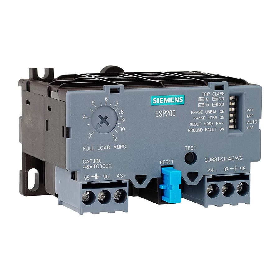
1 DIP Switch Settings
Trip Current:
125% of Full Load Current.
Phase Loss:
Trip time in < 3 seconds.
Ground Fault trip: Ground fault current > 60%
of present motor current.
Reset Mode:
Automatic or Manual.
CLASS 5
10
20
30
PHASE UNBAL ON
PHASE LOSS ON
RESET MODE MAN.
GROUND FAULT ON
Fig. 2
2 Wiring
Wire contactor per enclosed diagram.
(If ESP200 has windows) Push one motor lead through each pass-through
window in the overload relay, and connect to the contactor terminals (T1,T2,T3).
(Use only with 3-phase motors at 50/60Hz).
(If ESP200 has terminals) Connect each motor lead to the overload relay
terminals (T1, T2, T3).
(Use only with motors at 50/60 Hz).
Hazardous voltage.
Will cause death or serious injury
To avoid electrical shock or burn, turn off main and control
voltages before performing installation or maintenance.
Siemens Industry, Inc.
5300 Triangle Parkway, Norcross, GA 30092
CONTAINS THE
ENTIRE OBLIGATION
5
4
3
FULL LOAD AMPS
CAT.NO.
4 8 AT C 3 S 0 0
95
Fig. 1
ON
OFF
ON
OFF
OFF
OFF
AUTO
OFF
.
THIS EQUIPMENT CONTAINS HAZARDOUS VOLTAGES. DEATH,
INJURY, OR PROPERTY DAMAGE CAN RESULT IF SAFETY INSTRUCTIONS ARE NOT
FOLLOWED. ONLY QUALIFIED PERSONNEL SHOULD WORK ON OR AROUND THIS
EQUIPMENT AFTER BECOMING THOROUGHLY FAMILIAR WITH ALL WARNINGS,
SAFETY NOTICES, AND MAINTENANCE PROCEDURES CONTAINED HEREIN. THE
SUCCESSFUL AND SAFE OPERATION OF THIS EQUIPMENT IS DEPENDENT UPON
PROPER HANDLING, INSTALLATION, OPERATION AND MAINTENANCE.
QUALIFIED PERSON
FOR THE PURPOSE OF THIS MANUAL AND PRODUCT LABELS, A QUALIFIED PERSON
IS ONE WHO IS FAMILIAR WITH THE INSTALLATION, CONSTRUCTION AND
OPERATION OF THE EQUIPMENT, AND THE HAZARD INVOLVED. IN ADDITION, HE OR
SHE HAS THE FOLLOWING QUALIFICATIONS:
a) Is trained and authorized to energize, deenergize, clear, ground and tag circuits and
equipment in accordance with established safety practices.
OF
b) Is trained in the proper care and use of protective equipment such as rubber gloves, hardhat,
safety glasses or faceshields, flash clothing, etc., in accordance with established safety practices.
c) Is trained in rendering first aid.
6
TRIP CLASS
7
5
20
10
30
8
ESP200
PHASE UNBAL ON
OFF
9
PHASE LOSS ON
OFF
10
RESET MODE MAN
AUTO
GROUND FAULT ON
OFF
12
TEST
RESET
3 U B B 1 2 3 - 4 C W 2
A4-
97
98
96
A3+
MAN.
MAN.
Fig. 3
www.usa.siemens.com
E87010-A0354-T002-A1-14CL
SERIOUS PERSONAL
AUTO
95
O
95
O
96
O
96
O
AUTO
~ 3 min.
T3
T2
T1
(with windows)
T3
T2
T1
(with terminals)
100% FLA
100% FLA
1
Advertisement

Related Manuals for Siemens ESP200


Summary of Contents for Siemens ESP200
- Page 1 (T1,T2,T3). (Use only with 3-phase motors at 50/60Hz). (If ESP200 has terminals) Connect each motor lead to the overload relay terminals (T1, T2, T3). (Use only with motors at 50/60 Hz).
- Page 2 In addition to the markings on the dial there are clicks which allow for extremely fine tuning. Note that while thermal overload relays require a heater selection based on a relatively wide ampere range, the ESP200 overload relay has many clicks covering the same ampere range. See Fig 6.
- Page 3 FLA between 5 to 20 amperes. Similarly, motors that require only one-third, one-fourth, or one-fifth the overload’s FLA capability can use the same size ESP200 starter by looping three, four, or five times. The following table demonst rates how the looping process reduces the current setting of the overload by the number of times the wi res pass through the wind ows of the overload.
- Page 4 9 External Reset Button mounting instructions with the ESP200 The Blue reset button of the ESP200 is activated by pressing the Exterior reset button mounted on the outside of the equipment enclosure. When mounting the ESP200 inside an enclosure, the External reset rod must first be cut to length.
- Page 5 2 - 21/2 49ASMP2 3 - 4 49ASMP3 49ASMP* Mounting Kit The kit is used for remote mounting the ESP200 with fork terminal for wiring to contactors. 49ASMS1 49ASMS1 How to wire for Single Phase Motor Single Phase Magnetic Starter, Size 00–1...