Table of Contents
Advertisement
Quick Links
HVR-S270J/S270U/S270N/S270E/
SERVICE MANUAL
Ver. 1.1 2008.02
Revision History
Revision History
Revised-1
Replace the previously issued
SERVICE MANUAL 9-852-267-11
with this manual.
R MECHANISM (MDX-R201)
Link
Link
SPECIFICATIONS
MODEL INFORMATION TABLE
SERVICE NOTE
DISASSEMBLY
• Addition of "60i/50i SEL" Menu
The components identified by
mark 0 or dotted line with
mark 0 are critical for safety.
Replace only with part num-
ber specified.
HVR-S270J/S270U/S270N/S270E/S270P/S270C
9-852-267-12
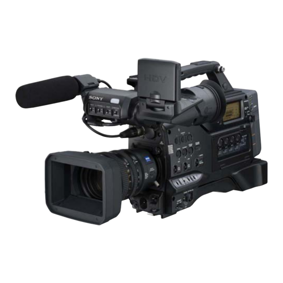
Photo: HVR-S270U
BLOCK DIAGRAMS
FRAME SCHEMATIC DIAGRAMS
SCHEMATIC DIAGRAMS
PRINTED WIRING BOARDS
Les composants identifiés par une
marque 0 sont critiques pour la
sécurité.
Ne les remplacer que par une pièce
portant le numéro spécifié.
DIGITAL HD VIDEO CAMERA RECORDER
Sony EMCS Co.
S270P/S270C
US Model
Canadian Model
AEP Model
Chinese Model
Japanese Model
REPAIR PARTS LIST
ADJUSTMENTS
INSTRUCTION MANUAL
Published by Kohda TEC
E Model
2008B0500-1
© 2008.2
Advertisement
Table of Contents

Related Manuals for Sony HVR-S270J


Summary of Contents for Sony HVR-S270J
- Page 1 0 are critical for safety. sécurité. Replace only with part num- Ne les remplacer que par une pièce ber specified. portant le numéro spécifié. DIGITAL HD VIDEO CAMERA RECORDER 2008B0500-1 HVR-S270J/S270U/S270N/S270E/S270P/S270C © 2008.2 Sony EMCS Co. 9-852-267-12 Published by Kohda TEC...
- Page 2 **Still image resolution is obtained by the Tape speed (DV SP) HDV recording 12.2 W unique pixel array of Sony’s ClearVid Approx. 18.812 mm/s DVCAM (DV) recording 11.7 W CMOS Sensor and image processing Recording/playback time (HDV)
- Page 3 **Still image resolution is obtained by the Tape speed (DV SP) HDV recording 12.5 W unique pixel array of Sony’s ClearVid Approx. 18.812 mm/s DVCAM (DV) recording 11.9 W CMOS Sensor and image processing During camera recording using the...
- Page 4 AUDIO 約 万画素 INPUT3/ 動画時有効画素数 ( : ) : AUDIO 約 万画素 INPUT4 端子 静止画時有効画素 数 ( : ) : 約 万画素 PHONES ステレオミニジャック 静止画時有効画素 数 ( : ) : 端子 (φ 3.5mm ) 約 万画素 HVR-S270J/S270U/S270N/S270E/S270P/S270C — 4 —...
- Page 5 Model information table Model HVR-S270J HVR-S270U HVR-S270N HVR-S270E HVR-S270P HVR-S270C Destination US, CND Color system NTSC NTSC NTSC • Abbreviation AR : Argentine model AUS : Australian model BR : Brazilian model CH : Chinese model CND : Canadian model...
- Page 6 CRITIQUES POUR LA SÉCURITÉ DE FONCTIONNEMENT. NE COMPONENTS WITH SONY PARTS WHOSE PART NUMBERS REMPLACER CES COMPOSANTS QUE PAR DES PIÈSES SONY APPEAR AS SHOWN IN THIS MANUAL OR IN SUPPLEMENTS DONT LES NUMÉROS SONT DONNÉS DANS CE MANUEL OU PUBLISHED BY SONY.
- Page 7 • 融点が従来の半田よりも約40℃高い。 り,プリント基板から浮かして取付けた部品がありま す。また内部配線は引きまわしやクランパによって発 従来の半田こてをそのまま使用することは可能です が,少し長めにこてを当てる必要があります。 熱部品や高圧部品に接近しないよう配慮されています ので,これらは必ずもとどおりにして下さい。 温度調節機能のついた半田こてを使用する場合,約 4. サービス後は安全点検を 350℃に設定して下さい。 注意: 半田こてを長く当てすぎると,基板のパター サービスのために取外したネジ,部品,配線がもとど おりになっているか,またサービスした個所の周辺を ン(銅箔)がはがれてしまうことがあります ので,注意して下さい。 劣化させてしまったところがないかなどを点検し,安 • 粘性が強い 全性が確保されていることを確認して下さい。 5. チップ部品交換時の注意 従来の半田よりも粘性が強いため, IC端子などが半田 • 取外した部品は再使用しないで下さい。 ブリッジしないように注意して下さい。 • 従来の半田と混ぜて使用可能 • タンタルコンデンサのマイナス側は熱に弱いため交 換時は注意して下さい。 無鉛半田には無鉛半田を追加するのが最適ですが, 従来の半田を追加しても構いません。 HVR-S270J/S270U/S270N/S270E/S270P/S270C — 7 —...
-
Page 8: Service Note
1) Select page: 0, address: 01, and set data: 01. 2) Select page: A, address: 10, set data: 00 and press the “PAUSE (Write) ” button of the adjustment remote commander. 3) Select page: 0, address: 01, and set data: 00. HVR-S270J/S270U/S270N/S270E/S270P/S270C... -
Page 9: Using Service Jig
C : Corrected by customer Indicates the appropriate Refer to “1-5-3. Self-diagnosis Code Table”. H : Corrected by dealer step to be taken. E : Corrected by service E.g. engineer 31 ..Reload the tape. 32 ..Turn on power again. HVR-S270J/S270U/S270N/S270E/S270P/S270C... - Page 10 Remove the battery or power cable, connect, and perform FG fault when starting drum. operations from the beginning. FG fault during normal drum Remove the battery or power cable, connect, and perform operations. operations from the beginning. HVR-S270J/S270U/S270N/S270E/S270P/S270C...
- Page 11 If an error occurs again, replace the lens block. Note: When replacing the LG-005 board, remove the EEPROM (IC6005) from the LG-005 board that is going to be repaired. Install the removed EEPROM (IC6005) to the replaced LG-005 board. HVR-S270J/S270U/S270N/S270E/S270P/S270C...
- Page 12 If an error occurs again, replace the lens block. Note: When replacing the LG-005 board, remove the EEPROM (IC6005) from the LG-005 board that is going to be repaired. Install the removed EEPROM (IC6005) to the replaced LG-005 board. HVR-S270J/S270U/S270N/S270E/S270P/S270C...
- Page 13 3 Select page: A, address: 99, set data: 01 and press the “PAUSE (Write) ” button of the adjustment remote commander. 4 Select page: 0, address: 01, and set data: 00. 5 Check that “60i/50i SEL” is displayed in the “OTHERS” of the “MENU” on the LCD screen. FP-760 FLEXIBLE BOARD (A-1539-015-A) VC-513 BOARD (SIDE A) CN1020 LCD screen HVR-S270J/S270U/S270N/S270E/S270P/S270C...
- Page 14 CN7309 2P 2 ショルダーパッドを外す。 安定化電源(+ 5Vdc) 3 CN7309を外す。 6 アイドラーギアを回し,テープの弛みを取る。 4 CN7501を外す。 (ミニカセットのみ) 1-3. 強制電源ONモードの設定 調整リモコン(RM-95またはNEW LANC JIG)を使用して,電源を入れることが出来ます。 VTR操作は調整リモコンで行えます。 1-3-1. 強制カメラ電源ONモードの設定 1) ページ:0,アドレス:01にデータ:01をセット。 2) ページ:A,アドレス:10にデータ:01をセットしPAUSE(Write)ボタンを押す。 1-3-2. 強制VTR電源ONモードの設定 1) ページ:0,アドレス:01にデータ:01をセット。 2) ページ:A,アドレス:10にデータ:02をセットしPAUSE(Write)ボタンを押す。 1-3-3. 強制電源ONモードの解除 1) ページ:0,アドレス:01にデータ:01をセット。 2) ページ:A,アドレス:10にデータ:00をセットしPAUSE(Write)ボタンを押す。 3) ページ:0,アドレス:01にデータ:00をセット。 HVR-S270J/S270U/S270N/S270E/S270P/S270C...
- Page 15 10 (11) EEP_SI_S 20 (1) XSYS_RST CN1018 注意: ( )内の端子番号は,VC-513基板CN1018のテスト 端子番号です。 CPC-13 (J-6082-443-A) 1-5. 自己診断機能 1-5-2. 自己診断表示 1-5-1. 自己診断機能について 本機の動作に不具合が生じたとき,ビューファインダまたは 本機の動作に不具合が生じたとき,自己診断機能が働き, LCD画面のカウンタ表示部分がアルファベットと数字の4桁 ビューファインダまたはL C D 画面に,どう処置したらよい 表示になり,3.2Hzで点滅します。この5文字の表示によっ か判断できる表示を行います。 自己診断機能については取扱 て対応者分類および不具合の生じたブロックの分類,不具合 説明書にも掲載されています。 の詳細コードを示します。 C : 3 1 : 1 1 HVR-S270J/S270U/S270N/S270E/S270P/S270C...
- Page 16 UNLOAD時,Sリール側テープ弛み バッテリまたは電源ケーブルを外して付け直し, 再度操作し直す。 Tリール異常 バッテリまたは電源ケーブルを外して付け直し, 再度操作し直す。 Sリール異常 バッテリまたは電源ケーブルを外して付け直し, 再度操作し直す。 TリールおよびSリールFGショート異常 バッテリまたは電源ケーブルを外して付け直し, 再度操作し直す。 リールモータ異常 バッテリまたは電源ケーブルを外して付け直し, 再度操作し直す。 キャプスタン起動時FG異常 バッテリまたは電源ケーブルを外して付け直し, 再度操作し直す。 ドラム起動時FG異常 バッテリまたは電源ケーブルを外して付け直し, 再度操作し直す。 ドラム定常時FG異常 バッテリまたは電源ケーブルを外して付け直し, 再度操作し直す。 バッテリまたは電源ケーブルを外して付け直し, 再度操作し直す。 復帰しない場合, レンズドライブブロックのフォーカスMRセンサ フォーカスが合いにくい (LG-005基板CN1003 ws, wf ピン) を点検。 問題がなければフォーカ (フォーカスの初期化ができない) スモータドライブ回路 (LG-005基板IC2001) を点検。 HVR-S270J/S270U/S270N/S270E/S270P/S270C...
- Page 17 合, LG-005基板を交換する。 ( 注意) エラーが再度発生する場合は, レンズブロックを交換する。 手振れ補正用ICとマイクロコント 手振れ補正回路 (LG-005基板IC4003) を点検。 ローラとの通信異常 EEPROM (LG-005基板IC6005) を点検。 復帰しない場合, LG- シフトレンズ初期化異常 005基板を交換する。 ( 注意) エラーが再度発生する場合は, レンズブロックを交換する。 LG-005基板のIC4003および周辺回路を点検。 復帰しない場 シフトレンズオーバーヒート 合, LG-005基板を交換する。 ( 注意) (PITCH) エラーが再度発生する場合は, レンズブロックを交換する。 注意 : LG-005基板を交換する場合は,修理するLG-005基板からEEPROM (IC6005) を取り外す。取り外したEEPROM (IC6005) は取り替えたLG-005基板に取り付ける。 HVR-S270J/S270U/S270N/S270E/S270P/S270C 1-10...
- Page 18 ENGLISH JAPANESE ENGLISH JAPANESE 自己診断コード ブロック 詳細 症状/状態 対応/方法 機能 コード LG-005基板のIC4003および周辺回路を点検。 復帰しない場 シフトレンズオーバーヒート 合, LG-005基板を交換する。 ( 注意) (YAW) エラーが再度発生する場合は, レンズブロックを交換する。 レンズドライブブロックとLG-005基板間の各フレキシブ ルフラットケーブルとコネクタの接続を確認する。 復帰し サーミスタの異常 ない場合, LG-005基板を交換する。 ( 注意) エラーが再度発生する場合は, レンズブロックを交換する。 注意 : LG-005基板を交換する場合は,修理するLG-005基板からEEPROM (IC6005) を取り外す。取り外したEEPROM (IC6005) は取り替えたLG-005基板に取り付ける。 HVR-S270J/S270U/S270N/S270E/S270P/S270C 1-11...
- Page 19 ENGLISH JAPANESE ENGLISH JAPANESE 1-6. “60i/50i切替” メニューの追加 調整リモコン(RM-95またはNEW LANC JIG)とFP-760フレキシブル基板(A-1539-015-A)を使用して,“60i/50i切替”メ ニューを追加することができます。 注意 : FP-760フレキシブル基板 (A-1539-015-A) を外すと “60i/50i切替” メニューは表示されません。FP-760フレキシブル基 板はVC-513基板のCN1020に接続したまま使用してください。 方法: 1 VC-513基板のCN1020にFP-760フレキシブル基板を接続する。 2 ページ:0,アドレス:01にデータ:01をセット。 3 ページ:A,アドレス:99にデータ:01をセットしPAUSE(Write)ボタンを押す。 4 ページ:0,アドレス:01にデータ:00をセット。 5 LCD画面で“MENU”の“その他”に“60i/50i切替”が表示されることを確認する。 FP-760 フレキシブル基板 (A-1539-015-A) VC-513基板(A面側) CN1020 LCD画面 HVR-S270J/S270U/S270N/S270E/S270P/S270C 1-12E...
-
Page 20: Note For Repair
It is possible that a wire is snapped. NOTE FOR DISCONNECTING THE HARNESS (COAXIAL CABLE) When disconnecting the harness (coaxial cable), do not pull the harness part but pull off the connector body with tweezers etc. Harness (Coaxial Cable) Tweezers etc. HVR-S270J/S270U/S270N/S270E/S270P/S270C... -
Page 21: Overall Section
⋅ EVF Panel Block ⋅ Cabinet (R) Block ⋅ Control Switch Block ⋅ Lens Mount Block ⋅ LCD Panel Block 2-2-7. OVERALL SECTION-4 ⋅ SD-037 Board ⋅ Connector Box Block 2-2-8. MAIN BOARD SECTION ⋅ VC-513 Board ⋅ DD-290 Board HVR-S270J/S270U/S270N/S270E/S270P/S270C... -
Page 22: Lens Block
3 Handle Block (3-1 to 3-6) 3-1 (#49) 3-4 (#122) 3-3 (#122) 3 Handle Block 2-2 (Loosen) Overall Section-2 (See Page 2-6) 1 Lens Block 2-1 (#126) 1-2 (Up) 2-7 (#50) HELP 1 2 EVF Block (See Page 2-4) 2-4 (#49) HVR-S270J/S270U/S270N/S270E/S270P/S270C... - Page 23 Follow the disassembly in the numerical order given. 1 EV-018 Board (1-1 to 1-14) 1-3 (#119) (Open) 1-14 EVF Mirror Tube Section (See Page 2-5) HELP 2 1-10 1-8 (#50) 1 EV-018 Board - 0 1 1-12 1-13 (#49) 1-5 (#122) 1-11 (#50) HVR-S270J/S270U/S270N/S270E/S270P/S270C...
-
Page 24: Control Switch Block
HELP 3 HELP 3 1 EVF Panel Block 3-1 (#119) 1-9 (#49) HELP 3 1-6 (#49) 3 LCD Panel 2-2 (Claw) Block 2-1 (#49) 2-8 (#49) HELP 4 1-10 2-5 (#49) 2-10 2-9 (#59) (#59) 1-2 (#59) 1-3 (#122) HVR-S270J/S270U/S270N/S270E/S270P/S270C... - Page 25 Follow the disassembly in the numerical order given. 1 Cabinet (L) Block (1-1 to 1-4) 2 MD Block (2-1 to 2-3) 1 Cabinet (L) Block 1-2 (Open) 2-2 (#31) 2 MD Block (See Page 2-7) 2-1 (#31) (#122) Overall Section-3 (See Page 2-8) HVR-S270J/S270U/S270N/S270E/S270P/S270C...
- Page 26 Follow the disassembly in the numerical order given. 1 NN-006 Board (1-1 to 1-7) 2 Mechanism Deck (2-1 to 2-4) 2 Mechanism Deck 2-3 (#130) 1 NN-006 Board HELP 5 1-4 (#50) 2-1 (#130) - 0 0 1-5 (#50) HVR-S270J/S270U/S270N/S270E/S270P/S270C...
-
Page 27: Overall Section
2 Lens Mount Block (2-1 to 2-7) Overall Section-4 (See Page 2-9) 1 Cabinet (R) Block Note: Refer to page 2-1 “Note for disconnecting the harness (coaxial cable)”. 1-5 (#122) 2 Lens Mount Block (Note) (Note) 2-7 (#122) 1-4 (#49) 1-1 (Screw) 2-6 (#122) HVR-S270J/S270U/S270N/S270E/S270P/S270C... -
Page 28: Help
Follow the disassembly in the numerical order given. 1 SD-037 Board (1-1 to 1-2) 2 Connector Box Block (2-1 to 2-6) Main Board Section (See Page 2-10) 1 SD-037 Board 1-1 (#50) HELP 6 - 0 3 2 Connector Box Block 2-6 (#133) HVR-S270J/S270U/S270N/S270E/S270P/S270C... -
Page 29: Help
1 VC-513 Board (1-1 to 1-5) 2 DD-290 Board (2-1 to 2-2) 2 DD-290 Board 2-2 (Claw) - 2 9 Center Chassis Block HELP 6 HELP 6 2-1 (#50) - 5 1 1 VC-513 Board 1-5 (#50) 1-1 (#50) HVR-S270J/S270U/S270N/S270E/S270P/S270C 2-10E... - Page 30 Sheet attachment positions and procedures of processing the flexible boards/harnesses are shown. HELP 1: HELP 3: SL-001 JJ-060/ES-001/PR-074/Tape AS FP-775 ES-001 Tape AS JJ-060 9mm 9mm PR-074 Ferrite Core SL-001 HELP 2: HELP 4: EVF Mirror Tube Block PR-074/SW-116 Slit EVF Mirror Tube Block PR-074 SW-116 EVF Main Block HVR-S270J/S270U/S270N/S270E/S270P/S270C HELP...
- Page 31 HELP 5: Protection Sheet/Tape AS Protection Sheet Tape AS Tape AS HELP 6: BD-057/DV-063/VD-053 VD-053 DV-063 FFC-122 Cord Clamp Wire Holder Boss BD-057 HVR-S270J/S270U/S270N/S270E/S270P/S270C HELP...
-
Page 32: Overall
OVERALL BLOCK DIAGRAM (8/14) POWER BLOCK DIAGRAM (6/10) OVERALL BLOCK DIAGRAM (9/14) POWER BLOCK DIAGRAM (7/10) POWER BLOCK DIAGRAM (8/10) OVERALL BLOCK DIAGRAM (10/14) OVERALL BLOCK DIAGRAM (11/14) POWER BLOCK DIAGRAM (9/10) POWER BLOCK DIAGRAM (10/10) OVERALL BLOCK DIAGRAM (12/14) HVR-S270J/S270U/S270N/S270E/S270P/S270C... - Page 33 OVERALL (6/14) IC_2201_VF_SYNC VREF (PAGE 3-6) AE15 (PAGE 3-6) AUIN21 CK64FSO AUIN22 FRRV, TRRV, DRP OVERALL (8/14) CKFSO OVERALL (5/14) (PAGE 3-8) ADATAIN0 (PAGE 3-5) CK64FSO MCLK OVERALL (9/14) ADATAIN1 CKFSO (PAGE 3-9) CK27MFO1 : VIDEO SIGNAL : AUDIO SIGNAL HVR-S270J/S270U/S270N/S270E/S270P/S270C...
- Page 34 F_GMR_A, F_GMR_B F_MR_A, F_MR_B 27MHz IC_2001/IC_3001_CK IC1503 SHIFT_Y_OUT YAW_AD_IC4003 IC_4003_CK CLOCK BUFFER GY-005 BOARD SHIFT_P_OUT PITCH_AD_IC4003 (8/8) ACTIVE LENS ACTUATOR SHIFT_P_DRIVE+, CN8501 SHIFT_P_DRIVE- P_DRIVE_A, P_DRIVE_B CN4001 SE8501 PITCH PITCH_AD PITCH SENSOR IC8501 SE8502 YAW_AD YAW SENSOR PITCH/ SENSOR DATA HVR-S270J/S270U/S270N/S270E/S270P/S270C...
- Page 35 XFTR_NR XFTR_NR (PAGE 3-7) MS_UPDATE_SW XLENS_IO_CTRL HI_SO, XHI_SCK HI_SI, HI_SO, XHI_SCK R_HOT LENS_DET_SW_M LENS_DET_SW_M XCS_CAMERA XCS_CAMERA PT_S ND_SW_AD ND_SW_AD Q1111, Q1112 LENS_DET_SW_E LENS DETECT OVERALL (6/14) IC4206 Q1110 NTSC/PAL_DET NTSC/PAL_DET NTSC/XPAL_DET_LG (PAGE 3-6) NTSC/PAL BUFFER DETECT (6/28) HI_SI_BO LENS_DET_SW_M HVR-S270J/S270U/S270N/S270E/S270P/S270C...
- Page 36 CN1003 EP_XVD EP_XVD CN5102 TC_PB_DATA (1/2) (1/2) VD_SO, VD_SO, VD_SO, VD_SO, VD_SO, OVERALL (6/14) VD_SCK VD_SCK VD_SCK VD_SCK XVD_SCK SI, SCK VD_SO, XVD_SCK VD_SO, XVD_SCK (PAGE 3-6) CN5106 (1/2) CN8001 (1/2) XRST_VTR XRST_VTR XRST_VTR XRST_VTR XRST_VTR XRST_VTR XRST_VTR RESET HVR-S270J/S270U/S270N/S270E/S270P/S270C...
- Page 37 OVERALL (1/14) AUENI RECA1 (PAGE 3-1) ADATAIN0 ADATAIN0 RECA2 OVERALL (7/14) HDV REC/PB, HDV-i.LINK ADATAIN1 ADATAIN1 (PAGE 3-7) EBS[0] - EBS[7] CK27MFO1 CK27MFO1 CKFSO CKFSO OVERALL (1/14) AD17 CK64FSO CK64FSO ERDY (PAGE 3-1) AD16 KCLK AD12 AD18 CKFSO CK64FSO HVR-S270J/S270U/S270N/S270E/S270P/S270C...
- Page 38 (15/28) IC_8006_XOE OVERALL (9/14) Q3601 32M FLASH (PAGE 3-9) OVERALL (14/14) XSYS_RST XCS_FLASH_VM XMS_LED_ON XCS_IC_7701 (15/28) (PAGE 3-14) DRIVE XCS_DA2 D7401 (MS ACCESS) VSP_SI, VSP_SO, XVSP_SCK IC_8006_XOE XO_SDI_HD50 XO_SDI_HD60 XO_SDI_SD OVERALL (10/14) O_SDI_CONFIG_ON (PAGE 3-10) I_SDI_CONFIG_DONE XO_CS_IC_8006 AB10 XO_RST_SDI HVR-S270J/S270U/S270N/S270E/S270P/S270C...
- Page 39 (3/3) : SERVO SIGNAL IC7504 (2/3) REEL MOTOR Q7503 Q7504 FG AMP S004 3 REEL PWM BUFFER REEL PWM (REC PROOF) DRIVER REC_PROOF REC_PROOF XREC_PROOF CN004 CHIME_SDA, CHIME_SDA, CHIME_3(SDA), CHIME_SCK CHIME_SCK CHIME_2(SCK) 4PIN CONNECTOR CN7501 M902 LM± CAM MOTOR HVR-S270J/S270U/S270N/S270E/S270P/S270C...
- Page 40 ATT_1 SIPA_RCK SHIFT ATT_2 REGISTER HP_OUT_SEL_1 HP_OUT_SEL_1 Q7001 (19/28) HP_OUT_SEL_2 HP_OUT_SEL_2 SIPA_ENABLE AU_CH1 AU_CH2 OVERALL (10/14) XPWAD2 (PAGE 3-10) IC7002 AU_MUTE_IC_3101 XVSP_SCK_ SHIFT HP_OUT_SEL_4 HP_OUT_SEL_4 REGISTER HP_OUT_SEL_5 HP_OUT_SEL_5 (19/28) ATT_3 IC7003 ATT_4 XVSP_SCK_ SHIFT REGISTER (19/28) : AUDIO SIGNAL HVR-S270J/S270U/S270N/S270E/S270P/S270C...
- Page 41 XCS_DA2 PROCESSOR XPOWER_DOWN_DA2 (21/28) IC7714 IC_7501_CH3 CKFSO_ BUFFER IC7703 CK64FSO_ (21/28) CK256FSO_ CONVERTER (21/28) IC7715 OVERALL (8/14) IC7707 IC_7501_CH4 VSP_SO_, XVSP_SCK_ AU_CH3 (PAGE 3-8) BUFFER IC_1801_ADAO2INV AU_CH4 (21/28) (21/28) CKFSO_ CK64FSO_ CK256FSO_ XPWAD2 VSP_SO_, XVSP_SCK_ IC_1801_ADAO2INV : AUDIO SIGNAL HVR-S270J/S270U/S270N/S270E/S270P/S270C...
- Page 42 HP_OUT_SEL_1 SWITCH Q7406 HP_OUT_SEL_2 SWITCH D7405 AU_MUTE_IC_3101 MUTE SWITCH Q7412, 7431, 7432 AU_MUTE1 MUTE MUTE MUTE CONTROL SWITCH SWITCH AU_MUTE2 OVERALL (1/14) Q7409, 7410 Q7407, 7408 Q7415 (PAGE 3-1) HP_MUTE MUTE MUTE CONTROL SWITCH Q7433, 7434 Q7413, 7414 HVR-S270J/S270U/S270N/S270E/S270P/S270C 3-10...
- Page 43 ATT_2 XLR_MIC/LINE_4 INPUT4_LINE_ON Q7615 REC_VOL_A/D_CH1 - REC_VOL_A/D_CH4 ATT_2 ATT_1 ATT_1 ATT_2 OVERALL (7/14) CH2 MIC XLR_LINE/MIC_1 LINE_1 XLR_MIC/LINE_2 (PAGE 3-7) INPUT CONTROL XLR_MIC/LINE_1 - CH1 MIC Q7616, Q7618, Q7620 XLR_LINE/MIC_2 LINE_2 XLR_MIC/LINE_1 XLR_MIC/LINE_4 INPUT CONTROL Q7617, Q7619, Q7621 HVR-S270J/S270U/S270N/S270E/S270P/S270C 3-11...
- Page 44 KEY_AD1 RV-003 BOARD PANEL_ CN6701 CN7806 REV_SW S5102 - S5104 S7801 - S7803, S6701 S7805, S7807 (PANEL REVERSE) SHOT TRANSITION/ FOCUS MARKING KEY_AD1 KEY_AD1 MEMORY PLAY INDEX DELETE KEY_AD2 KEY_AD2 KEY_AD2 KEY_AD2 S7808 XDISPLAY_ XDISPLAY_ XDISPLAY_ XDISPLAY_SW DISPLAY HVR-S270J/S270U/S270N/S270E/S270P/S270C 3-12...
- Page 45 XCAM_ON_SW XCAM_ON_SW DIAL_B_VM DIAL_B_VM DIAL_B_VM DIAL_A_VM DIAL_A_VM DIAL_A_VM VO-013 BOARD KEY_AD7 KEY_AD7 KEY_AD7 CN6402 AUDIO_ CN5601 RV5601 HP_VOL AUDIO_MONITOR_VOL MONITOR_VOL OVERALL (10/14) MONITOR (PAGE 3-10) CN6404 SP± SP± SP± SP901 OVERALL (8/14) SPEAKER : AUDIO SIGNAL (PAGE 3-8) HVR-S270J/S270U/S270N/S270E/S270P/S270C 3-13...
- Page 46 PEAKING IC_4001_SCK0, IC_4001_XCS0 FRONT_TALLY_SW BL_CONT BL_CONT OVERALL (4/14) FR_EVER_SO, FR_EVER_SCK X2ND_SS (PAGE 3-4) IC4501 VIDEO_LIGHT_SW D_1.0V N_DD_ON OVERALL (12/14) DC CONTROL SD_2.1V (PAGE 3-12) (27/28) XCS_DD2 AU_4.6V AU_5V, BL_5V SD_1.5V D4_-2.8V XB_TALLY_LED BL_-25V XF_TALLY_LED XDISPLAY_SW : SERVO SIGNAL HVR-S270J/S270U/S270N/S270E/S270P/S270C 3-14...
- Page 47 WAKE_UP XLANC_ON XO_LANCON XCTL2 XO_SCK_DD DIN, FR_EVER_SO, FR_EVER_SCK O_SO_DD XCS_DD1 XO_CS_DD XCS_DD2 XO_CS_DD2 XALART_N1 XALART XALART_N2 XHIDS_RST XO_HIRST C8 POWER (4/10) XSYS_RST (PAGE 3-18) XODO_SYSRST IC4501 DC CONTROL (1/2) (27/28) XALART_N2 XALART XALART_N1 N_DD_ON APPL_SW1, CTL1 DIN, XCS_DD2 HVR-S270J/S270U/S270N/S270E/S270P/S270C 3-15...
- Page 48 (PAGE 3-17) IC9207 BUFFER Q9206 - Q9208, Q9211 DC CONTROL TH9201 MOTOR_12V MOTOR_12V Q9209, Q9216, Q9217 Q9212, Q9215 F9202 L9201, L9204 N_8V N_8V Q9213, Q9214 F9203 L9205 MT_5.5V MT_5.5V F9204 OUT2_U, OUT2_D 1 IC9202 OUT1_U, DC CONTROL OUT1_D 1 HVR-S270J/S270U/S270N/S270E/S270P/S270C 3-16...
- Page 49 1.5V REG LX8a, IC4607 R4524 SD_1.5V (26/28) LX8b D_1.5V PVDD8a, VOUT PVDD8b L4623 A_3.3V L4620 LX8a, +INE9 L4614 D_3.3V LX8b OUT9-1 16V_IN Q4501 BL_-25V L4512 SWITCHING +INE10 BL_CONT -INE10 OUT10-1 POWER (8/10) Q4505, Q4506 (PAGE 3-22) EMERGENCY DETECT HVR-S270J/S270U/S270N/S270E/S270P/S270C 3-17...
- Page 50 (6/28) (6/28) (6/28) XSYS_RST_LG XO_RST_SDI (2/28) POWER (6/10) O_SDI_PWR_ON (PAGE 3-20) XSYS_RST XSYS_RST XRST_VTR POWER (9/10) XHIDS_RST CHIME_PWR_CONT (PAGE 3-23) POWER (1/10) VIDEO_LIGHT_ON POWER (3/10) (PAGE 3-15) (PAGE 3-17) MS_VCC_ON ENG_RST LENS_PWR_CTRL POWER (7/10) (PAGE 3-21) XSYS_RST XSYS_RST_LG HVR-S270J/S270U/S270N/S270E/S270P/S270C 3-18...
- Page 51 SAMPLE RATE SWITCH SELECTOR INVERTER IC7942 IC7944 IC7945 BUFFER IC7913 IC7910 IC7911 GENERATOR (21/28) (21/28) (21/28) CONVERTER (20/28) (20/28) CONVERTER (20/28) (20/28) (20/28) (21/28) (21/28) PROCESSOR IC7946 IC7947 (20/28) BUFFER BUFFER (20/28) (20/28) (21/28) (20/28) (20/28) DELAY BUFFER (20/28) HVR-S270J/S270U/S270N/S270E/S270P/S270C 3-19...
- Page 52 (22/28) IC8204 IC8217 (23/28) IC8205 BUFFER POWER (4/10) (23/28) O_IC_004_XON IC8222 IO(PLL4_OUTp) P16 (PAGE 3-18) Q8203 PS_XRESET BUFFER VCO823 IO(LVDS70n) (23/28) 27 MHz FPGA_XSD IO(VREFB7N0) Q8202 VCO822 74.25 MHz FPGA_XHD50 IO(LVDS101p) Q8201 VCO821 74.175824 MHz FPGA_XHD60 IO(LVDS101n) XO_RST_SDI HVR-S270J/S270U/S270N/S270E/S270P/S270C 3-20...
- Page 53 FOCUS MR F_GMR_VCC AUDIO LEVEL D2 XINIT SENSOR MF_SLIDE_LED CN7902 CN8901 F29 MF_SLIDE_LED D_2.8V D_2.8V D_2.8V Q1003 IR_RST_LED RST_IC_4003 F_RST_VCC G29 N.C. FOCUS RESET MI_LED RST_IC_2001/IC_3001 SENSOR H28 N.C. VAP_DD_ON F_RST_LED VAP_DD_ON AH4 FC_RST_SENS MANUAL ZOOM Z_PT_VCC POTENTIO METER HVR-S270J/S270U/S270N/S270E/S270P/S270C 3-21...
- Page 54 VDD(1.8V) CONTROL SWITCH VOUT BLOCK (GZ92000) FB6202 VDDIO(1.8V) LCD902 CN5803 L6203 EP_2.8V FB6203 VDDIO(3.0V) RV001 VOUT D_2.8V D_2.8V COLOR FB6204 VCC(3.0V) (HANDLE ZOOM) IC7802 2.8V REG UNIT XRST_VTR XRST_VTR RESET FP-783 FLEXIBLE BOARD CN7805 IC670 D_2.8V PANEL OPEN/CLOSE HVR-S270J/S270U/S270N/S270E/S270P/S270C 3-22...
- Page 55 (2/3) M903 DETECT, REEL FG CAPSTAN MOTOR CN7301 D_2.8V FG_VCC CAPSTAN (2/3) HE_VCC HE_VCC VH 17 HALL M901 CHIME_PWR_CONT DRUM MOTOR CN1014 CN7308 CN7304 XRST_VTR XRST_VTR XO_RST_VTR XO_RST_VTR FG_PG_COM SENSOR_VCC DRUM XRESET VREF PG/FG POWER (4/10) (PAGE 3-18) HVR-S270J/S270U/S270N/S270E/S270P/S270C 3-23...
- Page 56 AU_5V CONTROL R5308, R5309 BR_CTL Q9701 D9701 R5317, R5318, R5321, Q5311, Q5313 R5323, R5325 L5302 AUDIO IC9701 INPUT4 XLR_PWR_ON_4 XLR_PWR_ON_4 XLR_PWR_ON_4 DC/DC CONVERTER XLR_PWR_ON_4 XLR_PWR_ON_4 XLR_PWR_ON_4 L5301 R5303, R5305, R5307, R5311, R5312 XLR_PWR_ON_3 XLR_PWR_ON_3 XLR_PWR_ON_3 XLR_PWR_ON_3 XLR_PWR_ON_3 XLR_PWR_ON_3 HVR-S270J/S270U/S270N/S270E/S270P/S270C 3-24E...
- Page 57 BR-001 Board CN1015 CN9506 FS-088 BOARD CN8901 CN8501 GY-005 HDV/DV CN9707 CN9504 BOARD (Page 4-2) EJ-040 (SIDE A) BOARD FLEXIBLE FLAT CABLE CN8002 CN1018 (FFC-124) CN9502 CN9101 FLEXIBLE FLAT CABLE (For Check) (For Check) (FFC-121) CF-107 BOARD HVR-S270J/S270U/S270N/S270E/S270P/S270C FRAME (1/2)
- Page 58 TERMINAL LITHIUM BATTERY DC-109 DC-109 BOARD BOARD HARNESS FLEXIBLE FLAT CABLE (SIDE A) (SIDE B) (FJV-006) (IB-053) SB-040 BOARD CN6402 CN6404 CN6405 LC-094 BOARD CN8101 LC-094 BOARD (SIDE B) CN5601 (SIDE A) VO-013 ND8101 BOARD SP901 SPEAKER HVR-S270J/S270U/S270N/S270E/S270P/S270C FRAME (2/2)
- Page 59 VC-513 BOARD (14/28) LG-005 BOARD (4/8) (OIS DRIVE) (DS CONTROL, HI CONTROL) VC-513 BOARD (15/28) LG-005 BOARD (5/8) (IRIS DRIVE) (SDRAM, FLASH, EEPROM) LG-005 BOARD (6/8) (CAMERA CONTROL 1) VC-513 BOARD (16/28) (MECHA CONTROL) COMMON NOTE FOR SCHEMATIC DIAGRAMS HVR-S270J/S270U/S270N/S270E/S270P/S270C...
- Page 60 CONTROL SWITCH BLOCK (GZ92000) (LS-UU CONNECTION) TO-001 BOARD (HANDLE ZOOM SWITCH) RV-003 BOARD (PANEL REVERSE DETECT) FP-783 FLEXIBLE BOARD SW-514 BOARD (CONTROL SWITCH) (PANEL OPEN/CLOSE DETECT) UU-006 BOARD LC-094 BAORD (LCD, LCD DRIVE) (EVF DRIVE, A/D CONVERTER) COMMON NOTE FOR SCHEMATIC DIAGRAMS HVR-S270J/S270U/S270N/S270E/S270P/S270C...
- Page 61 TN-002 BOARD (CONTROL SWITCH) PW-135 BOARD (POWER/MODE SWITCH) VL-040 BOARD (VIDEO LIGHT TERMINAL) KR-001 BOARD DC-109 BOARD (DC OUT CONNECTOR) (SELECTION/EXECUTION SWITCH) MD-76 BOARD, FP-104, VO-013 BOARD (MONITOR VOLUME) FP-248 FLEXIBLE BOARD (MECHANISM BLOCK) COMMON NOTE FOR SCHEMATIC DIAGRAMS HVR-S270J/S270U/S270N/S270E/S270P/S270C...
-
Page 62: Schematic Diagrams
In addition, ensure that the receiver is not covered with dusts nor exposed to strong light. Les composants identifiés par une marque 0 sont critiques pour la sécurité. Ne les remplacer que par une pièce portant le numéro spécifie. HVR-S270J/S270U/S270N/S270E/S270P/S270C... - Page 63 緑 ダ 赤 XEDIT → EDIT PB/XREC → PB/REC 青 ・2は不燃性抵抗。 ・1はヒューズ抵抗。 ・Cはパネル表示名称。 ・AはB+ライン。 ・BはB−ライン。 ・JはBライン(+,−)の入出力方向を示す。 図a(映像入出力端子出力波形) ・Cは調整名称。 電子ビーム走査線 ・Aは未使用回路。 【電圧・波形測定条件ノート】 ・電圧値及び信号波形はパターンボックスのカラーバーチャート を被写体としたときの測定点対アース間の参考値。 ブラウン管の画像枠 (デジタルマルチメータ;入力インピーダンス DC10MΩ使 用) ・使用テスタの入力インピーダンスにより電圧値が多少異なりま す。 図b(テレビモニタの映像) イメージャ交換時の注意 ・イメージャを交換した場合は,カメラ部の全調整を 0印の部品,または0印付きの点線で囲まれた部品は, 行ってください。 安全性を維持するために重要な部品です。 従って交換時は,必ず指定の部品を使用して下さい。 ・イメージャは構造上,静電気により破壊される恐れが あるため,MOS ICと同様に注意して取り扱ってくだ お願い さい。 図面番号で部品を指定するときは基板名又はブロック また,受光部にはゴミの付着,および強い光がはいる を併せて指定して下さい。 ことのないように注意してください。 HVR-S270J/S270U/S270N/S270E/S270P/S270C...
- Page 64 C3033 R3017 1u B 0.1u D_SA_1.8V D_SA_1.8V C3016 C3034 1u B 0.1u EE-009 BOARD Note: EE-009 board and all mounted parts (including IC3001 (CMOS imager)) are not REG_GND CMOS IMAGER supplied, but they are included in PRISM device. HVR-S270J/S270U/S270N/S270E/S270P/S270C EE-009...
- Page 65 DOA6 R6032 DOA5 R6033 DOA4 R6034 R6011 DOA3 R6035 DOA2 R6036 CL6003 DOA1 R6037 DOA0 A_CP_PL_3.3V A_CP_PL_3.3V R6007 C6032 0.1u C6015 C6033 R6008 1u B 0.1u D_SA_1.8V D_SA_1.8V C6016 C6034 1u B 0.1u EE-010 BOARD REG_GND CMOS IMAGER HVR-S270J/S270U/S270N/S270E/S270P/S270C EE-010...
- Page 66 D_SC_1.8V R1250 0 DOB1 AD_G_B03 D_1.8V_G R1251 0 D_SA_1.8V DOB0 AD_G_B02 CN1202 20P D_DRV_1.8V D_2.8V_RGB C1222 LND122 D_DRV_1.8V SHASSI_GND REG_GND D_DRV_1.8V D_DRV_1.8V REG_GND D_DRV_1.8V D_1.8V_RGB_1 CN1205 30P VC-513 BOARD (1/28) REGULATOR XX MARK:NO MOUNT NO MARK:REC/PB MODE HVR-S270J/S270U/S270N/S270E/S270P/S270C VC-513 (1/28)
- Page 67 M2 M1 N7 H9 AA10 N2 P3 AA17 W7 P1 P7 J13 T1 AA2 U1 J14 AA20 U2 U4 AA21 VDD 1.2V VDDSHV1 AFE I/O 2.8V VC-513 BOARD (2/28) CAMERA SIGNAL PROCESS XX MARK:NO MOUNT NO MARK:REC/PB MODE HVR-S270J/S270U/S270N/S270E/S270P/S270C VC-513 (2/28)
- Page 68 DQ10 SD_DQ10 SD_DQ09 VSSQ SD_DQ08 VSSQ VSSQ SD_DQ07 G8 G9 F7 F3 G1 G2 G3 H1 H2 J3 G7 H9 H3 J7 H8 R8 N7 R9 N8 P9 M8 M7 VC-513 BOARD (3/28) SDRAM XX MARK:NO MOUNT HVR-S270J/S270U/S270N/S270E/S270P/S270C VC-513 (3/28)
- Page 69 BASE BAND SIGNAL PROCESS R1884 CK27MFO_OUT R1896 R1897 XX MARK:NO MOUNT CK13MFO1 R1885 L1804 10uH NO MARK:REC/PB MODE A_1.2V ∗:IMPOSSIBLE TO MEASURE THE IC1816 A_2.8V CK27MFO1 A_1.2V VOLTAGE AT THE MARKED POINTS. L1805 22uH A_2.8V A_2.8V HVR-S270J/S270U/S270N/S270E/S270P/S270C VC-513 (4/28) 4-10...
- Page 70 100k A_OUT B_OUT D1107 MA2S1110G8S0 NJM3403AV(TE2) IC1103 -0.4 R1164 BUFFER R1160 C1111 C1108 R1161 0.1u 0.1u D1106 MA2S1110G8S0 0.1u C1112 ENG_EX_IN D4_-2.8V ENG_ZM_POS_AD ENG_FC_POS_AD VC-513 BOARD (5/28) LENS-ENG LENS CONNECTION XX MARK:NO MOUNT NO MARK:REC/PB MODE HVR-S270J/S270U/S270N/S270E/S270P/S270C VC-513 (5/28) 4-11...
- Page 71 Tout DVCC AGND VREF XCS_SIO XCS_CAMERA SE4201 3 AXIS AVCC ACCELEROMETER XCS_LENS_SIO CAM_SO XCS_LENS_SIO HI_SO Reserved1 LENS_SO LENS_SO TC74VHC126FT(EL) TC74VHC125FT(EL) BUFFER BUFFER MS_UPDATE_SW VC-513 BOARD (6/28) CAMERA CONTROL 1 REG_GND XX MARK:NO MOUNT NO MARK:REC/PB MODE HVR-S270J/S270U/S270N/S270E/S270P/S270C VC-513 (6/28) 4-12...
- Page 72 AF17 AG17 A F18 AG18 A F19 AG19 A F20 AG20 A F21 AG21 A F22 AG22 A F23 AG23 A F24 AG24 A F25 AG25 A F26 AG26 A F27 AG27 A E26 AE27 AD26 A D27 A C26 A C27 A B26 A B27 A A26 A A27Y26 Y27 W26W27V26 V27 U26U27T26 T27 R26R27P26 P27 N26N27M26L26 L27 K26 J26 J27 H26G26G27F26 F27 E26 E27 D26 VC-513 BOARD (7/28) CAMERA CONTROL 2 HVR-S270J/S270U/S270N/S270E/S270P/S270C VC-513 (7/28) 4-13...
- Page 73 R2014 R2011 LINE_OUT_PR IC_1801_LNOPR Q2002 2SA2029T2LQ/R BUFFER R2002 ±0.5% R2015 R2012 LINE_OUT_C/PB IC_1801_LNOPB Q2003 2SA2029T2LQ/R BUFFER R2003 ±0.5% REG_GND C2001 A_2.8V C2002 FB2001 0.1u VC-513 BOARD (8/28) COMPONENT OUT AMP XX MARK:NO MOUNT NO MARK:REC/PB MODE HVR-S270J/S270U/S270N/S270E/S270P/S270C VC-513 (8/28) 4-14...
- Page 74 A1 F5 E4 C2 B1 G5 D2 E3 C1 F4 G4 D1 E2 F3 G3 E1 F2 G2 F1 G1 H5 H4 H1 H2 H3 J5 J1 J2 J3 J4 K1 K2 K3 K4 L1 L2 D_1.5V D_2.8V D_1.5V FB2801 VDD_1.5V_1 1.5V D_1.5V VDD_2.8V R2802 2.8V D_2.8V VDD_2.5V 2.5V D_2.5V C2801 C2828 C2829 FB2802 D_2.5V 2.2u B 6.3V REG_GND VC-513 BOARD (9/28) HDV INTERLACE/PROGRESSIVE CONVERTER XX MARK:NO MOUNT HVR-S270J/S270U/S270N/S270E/S270P/S270C VC-513 (9/28) 4-15...
- Page 75 B15 D15 E15 B14 D14 E14 A13 B13 D13 E13 A12 B12 D12 E12 A11 B11 D11 E11 A10 B10 D10 E10 M5 M4 M2 M1 N5 C2206 L2201 C2203 C2204 C2205 C2201 4.7u 0.1u 6.3V 6.3V 6.3V 6.3V REG_GND C2220 D_1.0V D_2.5V/1.8V VC-513 BOARD (10/28) A_1.0V A_1.0V HDV-MPEG VIDEO ENCODE/DECODE XX MARK:NO MOUNT HVR-S270J/S270U/S270N/S270E/S270P/S270C VC-513 (10/28) 4-16...
- Page 76 E1 D1 C1 A1 B1 D2 C2 A2 B5 A5 C5 D5 G8 G9 F7 F3 G1 G2 G3 H1 H2 J3 G7 J7 H8 R8 N7 R9 N8 P9 M8 M7 L8 L2 VC-513 BOARD (11/28) SDRAM, FLASH XX MARK:NO MOUNT HVR-S270J/S270U/S270N/S270E/S270P/S270C VC-513 (11/28) 4-17...
- Page 77 R2602 IC_3401 IC_7001 D_1.2V R2603 C2603 C2605 4.7u C2604 C2607 4.7u C2606 0.1u 4.7u 0.1u 6.3V 6.3V D_1.2V_K 6.3V D_1.2V_K R2604 REG_GND VC-513 BOARD (12/28) C2601 C2602 4.7u 0.1u HDV STREAM PROCESS 6.3V XX MARK:NO MOUNT HVR-S270J/S270U/S270N/S270E/S270P/S270C VC-513 (12/28) 4-18...
- Page 78 G2 H1 G4 H2 J1 H4 J2 K1 H5 L1 K2 R3409 6200 ±0.5% A_2.8V 10uH L3401 A_2.8V D_2.8V D_2.8V C3404 FB3401 4.7u 6.3V REG_GND C3415 C3401 0.1u 6.3V 24.576MHz X3401 VC-513 BOARD (13/28) HDV/DV i.LINK INTERFACE XX MARK:NO MOUNT HVR-S270J/S270U/S270N/S270E/S270P/S270C VC-513 (13/28) 4-19...
- Page 79 P20 H14 H11 G12 G13 A21 B20 G11 L18 D21 B17 E21 C18 C16 B18 A19 B19 C19 C20 A18 D19 C17 A17 A16 B16 E20 C21 G15 F18 E18 C3608 C3609 0.1u 0.1u Q3607-Q3609 LED DRIVE VC-513 BOARD (14/28) DS CONTROL, HI CONTROL XX MARK:NO MOUNT NO MARK:REC/PB MODE HVR-S270J/S270U/S270N/S270E/S270P/S270C VC-513 (14/28) 4-20...
- Page 80 6.3V REG_GND R3811 D_2.8V C3801 0.1u R3802 100k REG_GND 64K EEPROM AK6512CL-L IC3805 XCS_EEP XCS_EEP EEP_RXD3 HOLD EEP_RXD3 EEP_XRDY EEP_XRDY EEP_TXD3 EEP_TXD3 EEP_SCK3 EEP_SCK3 VC-513 BOARD (15/28) SDRAM, FLASH, EEPROM XX MARK:NO MOUNT NO MARK:REC/PB MODE HVR-S270J/S270U/S270N/S270E/S270P/S270C VC-513 (15/28) 4-21...
- Page 81 XO_SDI_HD50 XO_SDI_HD50 XO_SDI_HD60 XO_SDI_HD60 XO_CS_IC_8006 XO_CS_IC_8006 XO_RST_SDI XO_RST_SDI XO_SDI_SD XO_SDI_SD I_SDI_CONFIG_DONE I_SDI_CONFIG_DONE XO_SDI_BUFF_ON XO_SDI_BUFF_ON O_SDI_CONFIG_ON O_SDI_CONFIG_ON O_SDI_PWR_ON O_SDI_PWR_ON XSYS_RST XSYS_RST XCS_MC_FLASH XCS_MC_FLASH VC-513 BOARD (16/28) EEP_SI_S EEP_SI_S EEP_SO_S EEP_SO_S MECHA CONTROL EEP_SCK_S EEP_SCK_S XX MARK:NO MOUNT HVR-S270J/S270U/S270N/S270E/S270P/S270C VC-513 (16/28) 4-22...
- Page 82 6.3V R3106 4.7u C3168 4700 R3109 6.3V C3128 10 11 12 C3131 0.01u C3123 0.01u REG_GND REG_GND S_C_OUT S_C_I/O VIDEO_OUT VIDEO_I/O S_Y_OUT S_Y_I/O VC-513 BOARD (17/28) VIDEO OUT, SPEAKER AMP XX MARK:NO MOUNT NO MARK:REC/PB MODE HVR-S270J/S270U/S270N/S270E/S270P/S270C VC-513 (17/28) 4-23...
- Page 83 1 0 0 k ∗:IMPOSSIBLE TO MEASURE THE Q 7 5 0 9 U N R 9 2 A 1 G 0 8 S 0 VOLTAGE AT THE MARKED POINTS. R E G _ G N D HVR-S270J/S270U/S270N/S270E/S270P/S270C VC-513 (18/28) 4-24...
- Page 84 SHIFT REGISTER IC7002 TC74VHC595FT(EL) 4CH_REC XPWAD2 R7033 HP_OUT_SEL_4 SCLR HP_OUT_SEL_5 C7002 C7006 0.1u SHIFT REGISTER IC7003 TC74VHC595FT(EL) HPF_CH3 R7076 ATT_3 HPF_CH4 ATT_4 SCLR C7021 C7022 0.1u VC-513 BOARD (19/28) AUDIO SELECTOR XX MARK:NO MOUNT NO MARK:REC/PB MODE HVR-S270J/S270U/S270N/S270E/S270P/S270C VC-513 (19/28) 4-25...
- Page 85 0.1u B BUFFER IC7910 TC7SH125FU(T5RSOYF R7929 HDSDI_SDT1_OUT R7940 C7919 0.1u B IC7911 BUFFER TC7SH125FU(T5RSOYF R7927 HDSDI_SDT2_OUT R7938 C7920 0.1u B VC-513 BOARD (20/28) AUDIO CONVERTER NO MARK:REC/PB MODE ∗:IMPOSSIBLE TO MEASURE THE VOLTAGE AT THE MARKED POINTS. HVR-S270J/S270U/S270N/S270E/S270P/S270C VC-513 (20/28) 4-26...
- Page 86 C7793 R7793 C7734 3216 C7748 100k 0.01u 10u B SWITCH TC/XNT C7744 R7753 0.0022u 100k C7733 TC_PB_DATA R7778 VC-513 BOARD (21/28) TC/GNDOUT REG_GND 0.0047U B C7747 AUDIO SIGNAL PROCESS 2 XX MARK:NO MOUNT NO MARK:REC/PB MODE HVR-S270J/S270U/S270N/S270E/S270P/S270C VC-513 (21/28) 4-27...
- Page 87 3.5V(3.3V) ET8003 DCLK_1PIN ET8004 CONF_DONE_3PIN REG_GND REG_GND NCE_6PIN REG_GND REG_GND DATA_7PIN NCSO_8PIN REG_GND ASDO_9PIN SD_3.5V 2.8V SD_2.1V IC_8006_NCONFIG_OUT R8141 CONF_DONE D_3.3V D_3.3V R8148 R8149 R8150 VC-513 BOARD (22/28) SDI FORMATTER XX MARK:NO MOUNT NO MARK:REC/PB MODE HVR-S270J/S270U/S270N/S270E/S270P/S270C VC-513 (22/28) 4-28...
- Page 88 O_PLLREF VCO_GND R8261 BUFFER R8262 O_PLLVAR FIN-B VCO_INHIBIT PFD_OUT PFD_INHIBIT LOGIC_GND TEST C8217 IC_8006_A3.3V_5 R8293 R8294 0.1u B 0.47u R8298 XX PFD_INH ±0.5% 6.3v B R8274 ±0.5% VC-513 BOARD (23/28) XX MARK:NO MOUNT NO MARK:REC/PB MODE HVR-S270J/S270U/S270N/S270E/S270P/S270C VC-513 (23/28) 4-29...
- Page 89 DTC114EMT2L -VEE Q7406 -VSS DTC114EMT2L SWITCH C7493 0.1u C7405 C7408 0.1u L7402 10uH AU_5V BUFFER IC7404 TC74VHCT08AFT(EL) CH1/2 HP_OUT_SEL_5 C7409 0.1u CH3/4 HP_OUT_SEL_4 HP_OUT_SEL_1 HP_OUT_SEL_2 VC-513 BOARD (24/28) AUDIO OUT XX MARK:NO MOUNT NO MARK:REC/PB MODE HVR-S270J/S270U/S270N/S270E/S270P/S270C VC-513 (24/28) 4-30...
- Page 90 K2 K1 K3 L2 L3 H1 J1 A1 L1 A11 B9 C9 A9 A4 K4 L4 L10 L9 K10 B4 A3 B3 A2 B2 R4036 IC_4001_SCK0 R4028 R4004 IC_4001_SCK0 IC_4001_RXD0 IC_4001_RXD0 IC_4001_TXD0 IC_4001_TXD0 R4029 XHIDS_RST XHIDS_RST 0.01u CHARON_XCS0 C4004 CHARON_XCS0 OSD_V OSD_V R4006 XFUPSTAT XFUPSTAT X4001 XHIDSCON_MAD 32.768kHz XHIDSCON_MAD C4005 C4006 VC-513 BOARD (25/28) FRONT CONTROL XX MARK:NO MOUNT HVR-S270J/S270U/S270N/S270E/S270P/S270C VC-513 (25/28) 4-31...
- Page 91 DR_CH9A_LOWSIDE SWITCH Q4604 SCH2816-TL-E R4613 DRUM MOTOR DRIVE Q4601 SCH1406-TL-E R4615 DRUM_VS L4604 C4636 33uH 2.2u C4644 4.7u DR_CH10A_HISIDE VS10 Q4603 SCH2816-TL-E DR_CH10A_LOWSIDE SWITCH VC-513 BOARD (26/28) DC/DC CONVERTER 1 XX MARK:NO MOUNT NO MARK:REC/PB MODE HVR-S270J/S270U/S270N/S270E/S270P/S270C VC-513 (26/28) 4-32...
- Page 92 MCH5805-TL-E 100uH SWITCHING R4539 XX R4550 680k R4554 R4551 A_4.6V 150k Q4506 BL_CONT UNR91ABG08S0 DD_VREF R4553 XALART_N3 XALART_N3 Q4505, Q4506 EMERGENCY Q4505 DETECT UNR92A3G08S0 VC-513 BOARD (27/28) DC/DC CONVERTER 2 XX MARK:NO MOUNT NO MARK:REC/PB MODE HVR-S270J/S270U/S270N/S270E/S270P/S270C VC-513 (27/28) 4-33...
- Page 93 ∗ DELAY SWITCH (+) OUT IC1002 TC7S08FU(TE85R) DELAY BUFFER VTR_DD_ON VC-513 BOARD (28/28) GND Y N_DD_ON C1014 0.1u CONNECTOR C1008 C1009 XX MARK:NO MOUNT 0.1u 0.1u NO MARK:REC/PB MODE R E G _ G N D HVR-S270J/S270U/S270N/S270E/S270P/S270C VC-513 (28/28) 4-34...
- Page 94 MF_PT_VSS MF_P_VSS LG-005 BOARD (1/8) LENS DRIVE BLOCK is replaced as block (lens complete assy (SERVICE)), so that there PRINTED WIRING BOARD LENS CONNECTOR and SCHEMATIC DIAGRAM are omitted. NO MARK:REC/PB MODE R:REC MODE P:PB MODE HVR-S270J/S270U/S270N/S270E/S270P/S270C LG-005 (1/8) 4-35...
- Page 95 M1 K3 K4 M2 L3 J5 M3 L4 M4 K5 L5 M5 K6 L6 M6 J6 J7 M7 L7 K7 M8 L8 K8 M9 L9 M10 J8 L10 M11 K9 J9 L11 D_2.8V FB2001 D_2.8V C2008 C2011 C2014 0.1u 0.1u REG_GND MT_5V L2001 10uH MT_5V C2006 C2007 22u 10V MT_GND C2004 0.1u ZM_DRV_PWM ZM_DRV_ON ZM_DRV_BR LG-005 BOARD (2/8) LENS DRIVE XX MARK:NO MOUNT NO MARK:REC/PB MODE HVR-S270J/S270U/S270N/S270E/S270P/S270C LG-005 (2/8) 4-36...
- Page 96 M1 K3 K4 M2 L3 J5 M3 L4 M4 K5 L5 M5 K6 L6 M6 J6 J7 M7 L7 K7 M8 L8 K8 M9 L9 M10 J8 L10 M11 K9 J9 L11 D_2.8V FB3001 D_2.8V C3010 C3011 0.1u REG_GND R3032 MT_5V MT_5V C3004 C3005 MT_GND LG-005 BOARD (3/8) LENS DETECT XX MARK:NO MOUNT HVR-S270J/S270U/S270N/S270E/S270P/S270C LG-005 (3/8) 4-37...
- Page 97 P_DRIVE_A P_DRIVE_B Y_DRIVE_A Y_DRIVE_B REG_GND PITCH_HALL+ PITCH_AD_IC_4003 L4003 A_2.8V 10uH A_2.8V P_DRIVE_A P_DRIVE_B C4040 C4041 Y_DRIVE_A 0.1u Y_DRIVE_B REG_GND YAW_HALL+ YAW_AD_IC_4003 LG-005 BOARD (4/8) OIS DRIVE XX MARK:NO MOUNT NO MARK:REC/PB MODE R:REC MODE P:PB MODE HVR-S270J/S270U/S270N/S270E/S270P/S270C LG-005 (4/8) 4-38...
- Page 98 OUT1A I_DRIVE_A- MVCC2 0.1u OUT3A C3 C2 C1 D3 D1 E2 E3 E1 E4 F1 F2 G1 G2 C5014 0.01u R5015 B 25V XRST_IC_2001/IC_3001 LD_SCK XCS_SIO_LD LD_SO LD_SI LG-005 BOARD (5/8) IRIS DRIVE XX MARK:NO MOUNT HVR-S270J/S270U/S270N/S270E/S270P/S270C LG-005 (5/8) 4-39...
- Page 99 AJ1 AJ2 AJ3 AH3 AH4 AJ4 AJ5 AH5 AJ6 AH6 AJ7 AH7 AJ8 AH8 AG8 AG10AG12AG14 AJ9 AH9 AJ10 AH10AJ11 AH11AJ12 AH12AJ13 AH13AJ14 AH14AJ15 AH15AJ16 AH16AJ17 AH17AJ18 AH18AH19AJ19 AJ20 AH20AJ21 AH21AJ22 AH22AJ23 AH23AJ24 AJ25 AJ26 AJ27 AH24AH25AH26AH27AH29AJ29 EEP_SI EEP_SI IC_2001_SCK EEP_SO IC_2001_SCK EEP_SO EEP_SCK LD_SCK EEP_SCK LD_SCK XCS_SIO_LD XCS_SIO_LD XRST_IC_4003_CPU XRST_IC_4003_CPU C6015 XRST_IC_2001/IC_3001 XRST_IC_2001/IC_3001 IR_RST_SENS IR_RST_SENS FC_RING_SW FC_RING_SW ZM_M/S_SW ZM_M/S_SW LG-005 BOARD (6/8) CAMERA CONTROL 1 XX MARK:NO MOUNT NO MARK:REC/PB MODE HVR-S270J/S270U/S270N/S270E/S270P/S270C LG-005 (6/8) 4-40...
- Page 100 AF17 AG17AF18 AG18AF19 AG19AF20 AG20AF21 AG21AF22 AG22AF23 AG23AF24 AG24AF25 AG25AF26 AG26AF27 AG27AE26 AE27 AD26AD27AC26 AC27 AB26 AB27 AA26 AA27 Y26 Y27 W26 W27 V26 V27 U26 U27 T26 T27 R26 R27 P26 P27 N26 N27 M26 L26 L27 K26 J26 J27 H26 G26 G27 F26 F27 E26 E27 D26 LG-005 BOARD (7/8) CAMERA CONTROL 2 HVR-S270J/S270U/S270N/S270E/S270P/S270C LG-005 (7/8) 4-41...
- Page 101 (Page 4-57) 6.3V ZOOM_SW_AD ZOOM_SW_AD L1504 22uH D_2.8V D_2.8V A_2.8V C1510 C1512 X1501 6.3V 27MHz C1511 0.1u REG_GND BUFFER IC1503 C1508 HD74ALVC2G34USE-E 0.1u IC_2001/IC_3001_CK R1536 R1535 IC_4003_CK LG-005 BOARD (8/8) REGULATOR XX MARK:NO MOUNT NO MARK:REC/PB MODE HVR-S270J/S270U/S270N/S270E/S270P/S270C LG-005 (8/8) 4-42...
- Page 102 0.1u R8530 R8524 R8525 C8522 6.3V R8515 R8517 R8510 R8512 C8508 ±0.5% ±0.5% C8509 C8518 C8504 0.047u R8513 0.1u C8505 0.1u 0.33u C8515 ±0.5% 0.1u C8501 6.3V GY-005 BOARD PITCH/YAW SENSOR XX MARK:NO MOUNT NO MARK:REC/PB MODE HVR-S270J/S270U/S270N/S270E/S270P/S270C GY-005 4-43...
- Page 103 D_2.8V REG_GND REG_GND LENS_SI LENS_SI LENS_SO LENS_SO XLENS_SCK XLENS_SCK XCS_LENS_SIO XCS_LENS_SIO CAM_VD CAM_VD XSYS_RST XSYS_RST NTSC/PAL_DET NTSC/PAL_DET 1Pin 45Pin FP-766 FLEXIBLE BOARD FS-088 BOARD VC-LENS CONNECTION CONTROL SWITCH (PRINTED WIRING BOARD is omitted.) XX MARK:NO MOUNT HVR-S270J/S270U/S270N/S270E/S270P/S270C FP-766, FS-088 4-44...
- Page 104 D_2.8V LENS LN7901 FRONT_VOL_CH1 CHASSIS_GND VD7901 VD7904 VD7907 VD7910 VD7902 VD7905 VD7908 VD7911 VD7912 VD7906 VD7909 CN7902 X3RD_SS FS-088 KEY_AD3 CN8901 Through the D_2.8V Flexible Flat Cable FRONT_VOL_CH1 (FFC-339) (Page 4-44) REG_GND REG_GND LL-015 BOARD LENS CONNECTOR HVR-S270J/S270U/S270N/S270E/S270P/S270C LL-015 4-45...
- Page 105 Harness BATTERY (IB-053) CN9703 UNREG_12V UNREG_12V DD-290 UNREG_12V CN9201 LIGHT_UNREG_12V Through the Harness LIGHT_UNREG_12V (BD-057) (Page 4-71) Note: BT901, CN9901 and Harness (IB-053) are not included in BR-001 complete board. BR-001 BOARD DC IN NO MARK:REC/PB MODE HVR-S270J/S270U/S270N/S270E/S270P/S270C BR-001 4-46...
- Page 106 REG_GND TB8601 R8604 Flexible Flat Cable (1/6) (FJV-006) Pb_OUT COMPONENT (Page 4-46) REG_GND REG_GND TC_OUT REG_GND TB8601 TB8601 TC_GND (4/6) (6/6) REG_GND R8605 Pb/Cb AUDIO_L REG_GND AUDIO_R LN8602 CHASSIS_GND JK-351 BOARD VIDEO/AUDIO OUT JACK XX MARK:NO MOUNT HVR-S270J/S270U/S270N/S270E/S270P/S270C JK-351 4-47...
- Page 107 BR-001 CN9709 CN5201 Through the S VIDEO Flexible Flat Cable (FFC-118) BR-001 (Page 4-46) CN9710 Through the LN8401 Flexible Flat Cable (FFC-118) CHASSIS (Page 4-46) LN5201 CHASSIS_GND LA-029 BOARD SS-184 BOARD LANC JACK S VIDEO JACK HVR-S270J/S270U/S270N/S270E/S270P/S270C SS-184, LA-029 4-48...
- Page 108 AU_GND AU_GND Flexible Flat Cable Flexible Flat Cable (FFC-130) (FFC-130) REG_GND REG_GND (Page 4-65) (Page 4-34) REG_GND REG_GND X2ND_SS X2ND_SS REG_GND REG_GND 2ND_ZOOM_AD 2ND_ZOOM_AD REG_GND REG_GND IC_4201_AD IC_4201_AD REG_GND D_2.8V SH-029 BOARD CN5107 CONTROL SWITCH, RELAY CONNECTOR HVR-S270J/S270U/S270N/S270E/S270P/S270C SH-029 4-49...
- Page 109 Through the Through the Harness XCS_EVF_AD PANEL_G Harness (SL-001) (ES-001) REG_GND PANEL_B (Page 4-49) (Page 4-51) EP_XVD REG_GND EP_XHD REG_GND REG_GND BL_5V BL_5V BL_5V BL_5V BL_CONT BL_CONT BL_-V BL_-V XCS_LCD XCS_LCD XCS_LCD_AD XCS_LCD_AD REG_GND LE-041 BOARD RELAY CONNECTOR HVR-S270J/S270U/S270N/S270E/S270P/S270C LE-041 4-50...
- Page 110 (ES-001) PANEL_B (Page 4-50) BL_CONT REG_GND BL_-V REG_GND REG_GND BL_5V XRST_VTR BL_5V VD_SI BL_CONT VD_SO BL_-V FB7807 XVD_SCK XCS_LCD FB7808 XCS_LCD XCS_LCD_AD XCS_LCD_AD REG_GND C7821 C7822 LS-071 BOARD EVF CONTROL SWITCH XX MARK:NO MOUNT NO MARK:REC/PB MODE HVR-S270J/S270U/S270N/S270E/S270P/S270C LS-071 4-51...
- Page 111 BL_H BL_H C6003 Q6002 BL_H HN1B04FE-Y/GR(TPLR3) Q6001 R6014 R6012 DTA144EMT2L 4700 R6010 R6015 EXTDA CL6011 Q6003 BL_CONT TCOM2 HN1B04FE-Y/GR(TPLR3) R6009 C6007 3300 ±0.5% R6013 PP-006 BOARD LCD, LCD DRIVE, A/D CONVERTER XX MARK:NO MOUNT NO MARK:REC/PB MODE HVR-S270J/S270U/S270N/S270E/S270P/S270C PP-006 4-52...
- Page 112 S6701 LC-071 (PANEL REVERSE) CN6701 LS-071 CN7806 CN7805 PANEL_REV_SW Through the (Page 4-51) Harness REG_GND (SW-116) (Page 4-51) LND671 CHASSIS GND FP-783 FLEXIBLE BOARD RV-003 BOARD PANEL OPEN/CLOSE DETECT NO MARK:REC/PB MODE PANEL REVERSE DETECT HVR-S270J/S270U/S270N/S270E/S270P/S270C FP-775, RV-003, FP-783 4-53...
- Page 113 A1 A2 A3 A4 A5 A6 A7 A8 A9 A10 A11 A12 B12 C12 D12E12 F12 G12H12J12 4.7u XCS_EVF C6210 C6223 VD_SO 0.1u C6211 C6215 R6213 XRST_VTR RESET VCC(3.0V) FB6204 VCC(3.0V) C6227 REG_GND C6214 4.7u 0.047u R6207 4700 ± 0.5% C6212 C6213 2.2u 0.0047u 6.3V UU-006 BOARD EVF DRIVE, A/D CONVERTER HVR-S270J/S270U/S270N/S270E/S270P/S270C UU-006 4-54...
- Page 114 VCC(3.0V) VCC(3.0V) LND043 LND088 VCC(3.0V) LND044 VCC(3.0V) LND089 LND045 REG_GND REG_GND LND090 45Pin 1Pin EV-018 BOARD CONTROL SWITCH FP-776 FLEXIBLE BOARD XX MARK:NO MOUNT NO MARK:REC/PB MODE R:REC MODE P:PB MODE (PRINTED WIRING BOARD is omitted.) HVR-S270J/S270U/S270N/S270E/S270P/S270C FP-776, EV-018 4-55...
- Page 115 CF_ON CN9502 FP-796 REG_GND REG_GND FLEXIBLE EJ-040 REG_GND REG_GND LND001-LND014 CN9101 (Page 4-57) N.C. TPB- Through the Flexible Flat Cable EJECT_SW TPB+ (FFC-121) N.C. REG_GND (Page 4-57) RB9502 REG_GND TPA- TPA+ REG_GND REG_GND CF-107 BOARD HDV/DV CONNECTOR HVR-S270J/S270U/S270N/S270E/S270P/S270C CF-107 4-56...
- Page 116 AUTO 10Pin IRIS S004 PUSH AUTO CONTROL SWITCH BLOCK (LZ92000) FP-796 FLEXIBLE BOARD HOT SHOE CONTROL SWITCH BLOCK (LZ92000) is replaced as block, so that PRINTED WIRING BOARD is omitted. (PRINTED WIRING BOARD is omitted.) HVR-S270J/S270U/S270N/S270E/S270P/S270C FP-796, EJ-040, LZ92000 4-57...
- Page 117 R7404 XX Through the XMS_IN Flexible Flat Cable MSDATA1(NC) MS_DIO (FFC-123) R7405 XX (Page 4-34) MS_BS REG_GND CN7402 REG_GND MS_LED_ON D_2.8V REG_GND D7401 CN7401 R7401 CL-271HR-C-TS (MS ACCESS) LN7401 CHASSIS_GND MS-378 BOARD MS CONNECTOR XX MARK:NO MOUNT HVR-S270J/S270U/S270N/S270E/S270P/S270C MS-378 4-58...
- Page 118 C7007 0.01u 37 38 39 40 41 42 43 44 45 46 47 48 A_2.8V SW_PS C7014 0.01u B 25V CONT1 ALL_PS NN-006 BOARD(1/3) REC/PB AMP XX MARK:NO MOUNT NO MARK:REC/PB MODE R:REC MODE P:PB MODE HVR-S270J/S270U/S270N/S270E/S270P/S270C NN-006 (1/3) 4-59...
- Page 119 TOP_SENS R7542 ±0.5% MT_GND C7513 0.1u NN-006 BOARD (2/3) IC7502 TC7W34FU(TE12R) BUFFER SERVO O_PWM9_REEL_M XX MARK:NO MOUNT NO MARK:REC/PB MODE R:REC MODE R7516 R7533 P:PPB MODE ∗:IMPOSSIBLE TO MEASURE THE VOLTAGE AT THE MARKED POINTS. REG_GND HVR-S270J/S270U/S270N/S270E/S270P/S270C NN-006 (2/3) 4-60...
- Page 120 O_CM+ (5V) CM_LOAD O_CM+ A_5.0V O_LM- UNLOAD O_LM- REG_GND O_LM+ O_LM+ LOAD I_FG_TREEL TREEL_FG I_FG_TREEL LN7301 CN7309 REG_GND CHASSIS GND CM_+ CM_+ CM_UNLOAD LN7302 CM_- CM_- CM_LOAD CHASSIS GND NN-006 BOARD (3/3) CONNECTOR NO MARK:REC/PB MODE HVR-S270J/S270U/S270N/S270E/S270P/S270C NN-006 (3/3) 4-61...
- Page 121 Note: CN001 and CN002 are not supplied, but they are included in SD-037 complete board. LND001 ET001 REG_GND CHASSIS_GND LND002 CHASSIS_GND ET002 LND003 CHASSIS_GND LND004 ET003 CHASSIS_GND ET004 SD-037 BOARD HD/SD SDI OUT XX MARK:NO MOUNT NO MARK:REC/PB MODE HVR-S270J/S270U/S270N/S270E/S270P/S270C SD-037 4-62...
- Page 122 C7653 0.1u Q7602 4.7u 2SK2615 B 10V R7677 C7657 C7665 D7617 1.5u Q7605 MAS3132EGLS0 2SC6054GR8S0 R7678 Q7601 2SK3019TL R7674 R7688 R7621 SWITCH CONTROL A_GND XLR_PWR_ON_1 XLR_PWR_ON_2 ME-021 BOARD XLR INPUT 1 XX MARK:NO MOUNT NO MARK:REC/PB MODE HVR-S270J/S270U/S270N/S270E/S270P/S270C ME-021 4-63...
- Page 123 AU_LINE_4 C5359 1.5u BR-001 CN9702 Through the C5379 Flexible Flat Cable 1.5u 16.1 R5399 (FPD-001) 100k (Page 4-46) R5401 Q5311 2SC6054GR8S0 A_GND R5301 A_GND XLR_PWR_ON_3 XLR_PWR_ON_4 XL-009 BOARD XLR INPUT 2 XX MARK:NO MOUNT NO MARK:REC/PB MODE HVR-S270J/S270U/S270N/S270E/S270P/S270C XL-009 4-64...
- Page 124 D_2.8V (HANDLE ZOOM) 6Pin TO-001 BOARD CONTROL SWITCH BLOCK (GZ92000) HANDLE ZOOM SWITCH CONTROL SWITCH BLOCK (GZ92000) is replaced XX MARK:NO MOUNT as block, so that PRINTED WIRING BOARD is omitted. R:REC MODE P:PB MODE HVR-S270J/S270U/S270N/S270E/S270P/S270C FP-795, GZ92000, TO-001 4-65...
- Page 125 CN1006 CN1007 CN1008 Through the Through the Through the Flexible Flat Cable Flexible Flat Cable Flexible Flat Cable (FFC-156) (FFC-156) (FFC-156) (Page 4-34) (Page 4-34) (Page 4-34) SW-514 BOARD CONTROL SWITCH XX MARK:NO MOUNT NO MARK:REC/PB MODE HVR-S270J/S270U/S270N/S270E/S270P/S270C SW-514 4-66...
- Page 126 KEY_AD_4_5_OUT KEY_AD4_5_OUT R8113 R8114 R8115 REG_GND D_2.8V D_2.8V LCD_5V D8104-D8106 LCD_5V (LCD BACKLIGHT) A_4.6V A_4.6V REG_GND REG_GND REG_GND REG_GND REG_GND LC-094 BOARD LN8101 LCD, LCD DRIVE CHASSIS GND LN8102 XX MARK:NO MOUNT CHASSIS GND NO MARK:REC/PB MODE HVR-S270J/S270U/S270N/S270E/S270P/S270C LC-094 4-67...
- Page 127 KEY_AD5 KEY_AD7 KEY_AD7 REG_GND LN6605 SHASSI_GND_5 PW-135 TN-002 CN6802 CN5901 Through the Through the Flexible Flat Cable Flexible Flat Cable (FFC-118) (FFC-118) (Page 4-69) (Page 4-69) SB-040 BOARD CONTROL SWITCH XX MARK:NO MOUNT R:REC MODE P:PPB MODE HVR-S270J/S270U/S270N/S270E/S270P/S270C SB-040 4-68...
- Page 128 KEY_AD5 VD6802 KEY_AD7_2 KEY_AD6_2 CAMERA S6801 S6802 POWER S5901 S5902 S5903 S5904 MENU ON PRESET GAIN STATUS BARS MENU PRST WHT BAL OUTPUT (OFF) STATUS PW-135 BOARD TN-002 BOARD POWER/MODE SWITCH CONTROL SWITCH XX MARK:NO MOUNT HVR-S270J/S270U/S270N/S270E/S270P/S270C TN-002, PW-135 4-69...
- Page 129 CHASSIS GND SW-514 REG_GND CN6402 8200 Through the REG_GND S6906 VD6906 Flexible Flat Cable AUDIO_MONITOR_VOL (FFC-118) SLOW (Page 4-66) REG_GND REG_GND VOL 3.5V MONITOR PB-001 BOARD VO-013 BOARD VIDEO CONTROL SWITCH XX MARK:NO MOUNT MONITOR VOLUME HVR-S270J/S270U/S270N/S270E/S270P/S270C KR-001, VO-013, PB-001 4-70...
- Page 130 0.1u R9250 CONVERTER R9251 C9246 0.022u BUFFER SI4884DY-T1 100k Q9224 R9259 16.5 C9248 0.47u 16.7 SWITCH 220k R9255 R9256 R9257 Q9223 2SC4177-T1L5L6 DC CONTROL R9258 0.022u C9247 DD-290 BOARD DC/DC CONVERTER XX MARK:NO MOUNT NO MARK:REC/PB MODE HVR-S270J/S270U/S270N/S270E/S270P/S270C DD-290 4-71...
- Page 131 CN5703 LIGHT_GND LIGHT_GND D5702 MAZS220G08S0 C5702 0.22u LN5701 CHASSIS_GND CHASSIS_GND VL-040 BOARD VIDEO LIGHT TERMINAL SW_+12V CN9402 C9401 EXT_DC(12V) 0.22u UNREG_GND UNREG_GND CN9401 BR-001 CN9706 Through the Harness (DD-064) (Page 4-46) DC-109 BOARD DC OUT CONNECTOR HVR-S270J/S270U/S270N/S270E/S270P/S270C VL-040, DC-109 4-72...
- Page 132 Note: CN004 and S004 are not CL037 T REEL FG S REEL FG CHIME_3 (SDA) IC004 IC005 included in FP-104 flexible board. CL038 R014 TLP907 (LB, SONY) TLP907 (LB, SONY) CHIME_2 (SCK) CL039 CL040 JL001 S004 CL041 (REC PROOF) TAPE_TOP...
- Page 133 LA-029 BOARD TO-001 BOARD SH-029 BOARD SW-514 BOARD (SIDE A) LE-041 BOARD SW-514 BOARD (SIDE B) LS-071 BOARD LC-094 BOARD (SIDE A) PP-006 BOARD LC-094 BOARD (SIDE B) RV-003 BOARD SB-040 BOARD (SIDE A) COMMON NOTE FOR SCHEMATIC DIAGRAMS HVR-S270J/S270U/S270N/S270E/S270P/S270C...
- Page 134 TO (1/2) Link TO (1/2) Link SB-040 BOARD (SIDE B) DD-290 BOARD TN-002 BOARD VL-040 BOARD PW-135 BOARD DC-109 BOARD KR-001 BOARD MD-76 BOARD VO-013 BOARD FP-104 FLEXIBLE BOARD PB-001 BOARD FP-248 FLEXIBLE BOARD COMMON NOTE FOR SCHEMATIC DIAGRAMS HVR-S270J/S270U/S270N/S270E/S270P/S270C...
-
Page 135: Printed Wiring Boards
• Through hole is omitted. • There are a few cases that the part printed on diagram isn’t mounted in this model. • C: panel designation (JAPANESE) プリント図共通ノート 【プリント図ノート】 ・ :無鉛半田を使用しています。 ・ :基板 :フレキシブル配線板 見ている面側のパターン。 :裏側のパターン (他のパターンについては表示されていません) ・スルーホールは省略。 ・プリント図には,本機で使用していない部品が記載されている 場合があります。 ・Cはパネル表示名称。 HVR-S270J/S270U/S270N/S270E/S270P/S270C 4-74... - Page 136 R6012 C6027 C6031 C6035 A_DAR_3.3V C6030 C6025 C6013 C6038 C6016 1-874-026- 1-874-026- CL6002 CL6003 D_SA_1.8V Note: EE-010 board and all mounted parts (including IC6001 (CMOS imager)) are not supplied, but they are included in PRISM device. HVR-S270J/S270U/S270N/S270E/S270P/S270C EE-009, EE-010 4-75...
- Page 137 C7027 R1131 L2001 R1123 R7084 IC1001 R1169 R1157 R7085 R1117 C7026 R1124 C1110 C1003 C1004 C1002 Note: IC3804 is not supplied, but this is included in VC-513 complete board. CN1006 CN1007 CN1008 CN1019 1-874-275- 11 HVR-S270J/S270U/S270N/S270E/S270P/S270C VC-513 (SIDE A) 4-76...
- Page 138 R7499 FB4401 C4416 R4405 C4408 R4402 R7431 R7444 C7506 CL4405 Note: IC2402 and IC4201 are not supplied, but they are CL8009 included in VC-513 complete board. D_1.5V C8044 R8158 C8043 R1002 R1003 CN8002 CN1018 1-874-275- HVR-S270J/S270U/S270N/S270E/S270P/S270C VC-513 (SIDE B) 4-77...
- Page 139 E2 F2 G2 H2 J2 K2 L2 M2 C2015 D_1.8V A1 B1 C1 D1 E1 F1 G1 H1 J1 K1 L1 M1 R2013 C2016 R2012 R2007 C2002 R1534 D1005 C1001 L1001 C1507 R2009 D_2.8V C2001 1-873-486- HVR-S270J/S270U/S270N/S270E/S270P/S270C LG-005 (SIDE A) 4-78...
- Page 140 AE28 AD28 AC28 AB28 AA28 AJ29 AH29 AG29 AF29 AE29 AD29 AC29 AB29 AA29 R6030 C6010 C6017 R6033 FB6001 R6019 R6018 1-873-486- Note: IC6005 is not supplied, but this is included in LG-005 complete board. HVR-S270J/S270U/S270N/S270E/S270P/S270C LG-005 (SIDE B) 4-79...
- Page 141 1-874-250- 11 FS-088 BOARD (SIDE B) LN7901 AUDIO LEVEL CN7902 1-874-257- 11 (OFF) LL-015 BOARD (SIDE B) SHUTTER VD7912 R7907 S8903 R7906 VD7908 R7910 R7905 1-874-250- 11 R7911 R7904 R7902 R7901 R7909 LENS 1-874-257- 11 HVR-S270J/S270U/S270N/S270E/S270P/S270C GY-005, FS-088, LL-015 4-80...
- Page 142 Note: IC9701 is not supplied, but this is included in BR-001 complete board. CN9701 L9701 C9701 C9703 R9707 R9702 D9701 R9706 Q9701 C9711 R9701 IC9701 C9709 C9708 R9705 L9704 C9710 R9704 C9707 Q9702 L9703 C9704 C9705 CN9707 CN9708 F9701 TH9703 BREAKER CN9703 1-874-235- 11 1-874-235- 11 HVR-S270J/S270U/S270N/S270E/S270P/S270C BR-001 4-81...
- Page 143 SS-184 BOARD (SIDE A) 1-874-252- 11 LN5201 R5202 LA-029 BOARD (SIDE A) LA-029 BOARD (SIDE B) R5201 1-874-368- 11 SS-184 BOARD (SIDE B) R8401 R8402 LANC J8401 R8403 S VIDEO LN8401 1-874-368- 11 1-874-254- 11 1-874-254- 11 HVR-S270J/S270U/S270N/S270E/S270P/S270C JK-351, SS-184, LA-029 4-82...
- Page 144 SH-029 (4 layers) : Uses unleaded solder. SH-029 BOARD (SIDE A) SH-029 BOARD (SIDE B) CN5104 SHOT TRANSITION/ LD5101 FOCUS MARKING CHECK STORE EXEC CN5105 LIGHT SHOT TRANSITION/ AUTO FOCUS MARKING LD5102 S5101 1-874-285- 11 1-874-285- 11 HVR-S270J/S270U/S270N/S270E/S270P/S270C SH-029 4-83...
- Page 145 LE-041 (2 layers) : Uses unleaded solder. LE-041 BOARD (SIDE A) 1-874-256- 11 LE-041 BOARD (SIDE B) CN8004 1-874-256- 11 HVR-S270J/S270U/S270N/S270E/S270P/S270C LE-041 4-84...
- Page 146 VD7805 R7805 VD7803 R7802 R7803 VD7807 R7807 VD7806 R7801 R7809 CN7801 CN7802 C7804 FB7808 FB7807 L7802 C7806 C7822 C7821 R7810 R7815 L7801 C7805 C7801 C7810 C7807 R7813 R7808 C7808 CN7804 R7806 VD7802 CN7806 CN7805 CN7803 1-874-258- 11 HVR-S270J/S270U/S270N/S270E/S270P/S270C LS-071 4-85...
- Page 147 C6020 C6010 C6021 C6008 EP_1.8V CL6006 CL6007 C6022 CL6001 CL6002 CL6003 CL6004 CL6005 CN6001 C6006 EP_2.8V RV-003 BOARD RV-003 BOARD LND601 (SIDE A) (SIDE B) 1-874-276- 11 1-874-263- 11 (PANEL REVERSE) 1-874-265- 11 1-874-265- 11 HVR-S270J/S270U/S270N/S270E/S270P/S270C PP-006, RV-003, FP-783 4-86...
- Page 148 FB6202 C6207 C6202 C6219 C6203 C6206 C6204 EP_2.8V EP_1.8V C6222 CN6201 1-874-270- 11 1-874-270- 11 EV-018 BOARD CN9001 D9002, D9003 REC LAMP (FRONT) Q9001 LN9002 LN9001 COMPOSITE VIDEO OUT LIGHT PEAKING TALLY D9001 1-874-249- 11 (LIGHT) HVR-S270J/S270U/S270N/S270E/S270P/S270C UU-006, EV-018 4-87...
- Page 149 CF-107 (2 layers), EJ-040 (2 layers) : Uses unleaded solder. CF-107 BOARD (SIDE A) CF-107 BOARD (SIDE B) CN9502 R9501 TH9504 TH9503 TH9502 TH9501 RB9502 HDV/DV CN9504 1-874-236- 11 1-874-236- 11 EJ-040 BOARD S9101 1-874-248- 11 HVR-S270J/S270U/S270N/S270E/S270P/S270C CF-107, EJ-040 4-88...
- Page 150 MS-378 (2 layers) : Uses unleaded solder. MS-378 BOARD (SIDE A) MS-378 BOARD (SIDE B) CN7401 R7401 (MS ACCESS) MEMORY STICK 1-874-260- 11 1-874-260- 11 HVR-S270J/S270U/S270N/S270E/S270P/S270C MS-378 4-89...
- Page 151 C7562 R7521 R7564 R7525 C7568 R7534 C7513 C7001 C7510 R7512 R7511 C7542 CL7505 C7541 R7007 C7013 C7554 R7010 IC7001 R7008 R7584 R7009 R7011 C7018 IC7002 C7016 L7003 R7015 R7014 R7013 R7012 1-874-261- CN7301 CN7304 CN7001 HVR-S270J/S270U/S270N/S270E/S270P/S270C NN-006 (SIDE A) 4-90...
- Page 152 NN-006 (4 layers) : Uses unleaded solder. NN-006 BOARD (SIDE B) C7302 IC7301 R7553 R7303 R7304 IC7505 C7551 L7503 R7546 R7547 R7548 Q7505 R7571 R7572 CN7309 CN7501 1-874-261- HVR-S270J/S270U/S270N/S270E/S270P/S270C NN-006 (SIDE B) 4-91...
- Page 153 R007 C020 ET003 ET004 R048 FB004 C014 C013 R023 R047 R005 R006 R002 IC001 R001 R052 R004 C001 1-873-097- 11 1-873-097- 11 Note: CN001 and CN002 are not supplied, but they are included in SD-037 complete board. HVR-S270J/S270U/S270N/S270E/S270P/S270C SD-037 4-92...
- Page 154 R7639 R7619 R7627 R7620 C7612 C7604 Q7612 R7633 IC7602 AUDIO R7613 C7601 R7637 C7609 INPUT2(R) R7647 C7620 R7636 R7614 R7703 R7632 Q7614 R7612 R7714 R7611 R7615 L7601 R7713 Q7618 Q7620 Q7616 C7619 CN7601 1-874-259- 11 1-874-259- 11 HVR-S270J/S270U/S270N/S270E/S270P/S270C ME-021 4-93...
- Page 155 Q5313 C5344 R5351 Q5311 R5325 R5401 L5302 R5323 C5363 R5321 R5385 C5312 C5304 R5317 R5359 AUDIO INPUT4 R5338 IC5301 C5309 R5311 C5301 R5352 R5307 L5301 R5305 R5408 R5303 C5317 Q5314 Q5320 R5360 R5406 1-874-274- 11 1-874-274- 11 HVR-S270J/S270U/S270N/S270E/S270P/S270C XL-009 4-94...
- Page 156 FP-795 (1 layer), TO-001 (2 layers) : Uses unleaded solder. FP-795 FLEXIBLE BOARD TO-001 BOARD (SIDE A) REC LAMP (BACK) VD5804 R5801 R5810 S5801 CN8801 1-874-269- 11 (HANDLE ZOOM) R8808 R8804 TO-001 BOARD (SIDE B) 1-874-269- 11 PHONES 1-874-782- 11 HVR-S270J/S270U/S270N/S270E/S270P/S270C FP-795, TO-001 4-95...
- Page 157 Danger of explosion if battery is incorrectly replaced. Replace only with the same or equivalent type. Note: SW-514基板のリチウム電池(BT6401)を交換す る場合はバッテリホルダ(BH6401)も同時に新 注意 品に交換してください。(一度使用したバッテリ 電池の交換は,正しく行わないと破裂する恐れがあり ホルダは再使用できません。) ます。電池を交換する場合には必ず同じ型名の電池 部品取り付けの際は,先にバッテリホルダを取り 付けてからリチウム電池を装着してください。 又は同等品と交換してください。 HVR-S270J/S270U/S270N/S270E/S270P/S270C SW-514 (SIDE A) 4-96...
- Page 158 SW-514 (2 layers) : Uses unleaded solder. SW-514 BOARD (SIDE B) CN6405 CN6404 CN6402 VD6402 VD6401 RV6404 RV6403 RV6402 RV6401 R6409 CN6407 CN6406 CN6403 1-874-267- 11 HVR-S270J/S270U/S270N/S270E/S270P/S270C SW-514 (SIDE B) 4-97...
- Page 159 LC-094 (2 layers) : Uses unleaded solder. LC-094 BOARD (SIDE A) D8103 WARNING TC/U-BIT LN8102 R8111 R8113 R8114 R8115 D8104 - D8106 (LCD BACKLIGHT) VD8101 CH1/2 AUDIO LEVEL BACKLIGHT DISPLAY CH3/4 1-874-255- HVR-S270J/S270U/S270N/S270E/S270P/S270C LC-094 (SIDE A) 4-98...
- Page 160 LC-094 (2 layers) : Uses unleaded solder. LC-094 BOARD (SIDE B) ND8101 LN8101 R8119 R8120 R8106 C8107 R8105 L8104 C8106 R8104 IC8101 IC8102 C8105 R8103 L8103 C8104 R8118 L8102 C8102 C8112 CN8101 1-874-255- 11 HVR-S270J/S270U/S270N/S270E/S270P/S270C LC-094 (SIDE B) 4-99...
- Page 161 SB-040 (2 layers) : Uses unleaded solder. SB-040 BOARD (SIDE A) LN6602 LN6603 ASSIGN PICTURE PROFILE ZEBRA AE SHIFT STEADY SHOT D001 D002 LN6604 D003 CAMERA MODE VD6601 VD6602 AUTO CAMERA MODE MANUAL LN6605 LN6601 1-874-266- 11 HVR-S270J/S270U/S270N/S270E/S270P/S270C SB-040 (SIDE A) 4-100...
- Page 162 SB-040 (2 layers) : Uses unleaded solder. SB-040 BOARD (SIDE B) Q002 Q001 R6611 R6610 Q003 CN6603 CN6602 1-874-266- 11 HVR-S270J/S270U/S270N/S270E/S270P/S270C SB-040 (SIDE B) 4-101...
- Page 163 S5903 S5902 S5901 S6801 CAMERA STATUS VD6802 1-874-268- 11 S6802 POWER 1-874-264- 11 KR-001 BOARD (SIDE A) KR-001 BOARD (SIDE B) VO-013 BOARD RV5601 SEL/PUSH EXEC MONITOR 1-874-253- 11 CN5601 1-874-253- 11 1-874-272- 11 HVR-S270J/S270U/S270N/S270E/S270P/S270C TN-002, PW-135, KR-001, VO-013 4-102...
- Page 164 : Uses unleaded solder. PB-001 BOARD (SIDE A) LN6902 S6907 S6908 S6909 S6910 S6911 DATA CODE REVIEW STOP PLAY PAUSE SLOW S6901 S6902 S6903 S6904 S6905 S6906 1-874-262- 11 PB-001 BOARD (SIDE B) CN6901 LN6901 1-874-262- 11 HVR-S270J/S270U/S270N/S270E/S270P/S270C PB-001 4-103...
- Page 165 R9210 R9208 C9202 R9205 R9207 R9254 Q9217 Q9216 Q9209 D9208 C9251 R9253 R9255 R9256 R9257 D9206 C9248 R9259 Q9221 D9201 D9203 D9202 F9201 Q9222 Q9220 Q9219 R9246 R9241 R9248 LN9203 LN9204 CN9201 LN9202 LN9205 1-874-239- 1-874-239- 11 HVR-S270J/S270U/S270N/S270E/S270P/S270C DD-290 4-104...
- Page 166 VL-040 BOARD (SIDE B) CN5702 CN5703 12V MAX 35W LIGHT 1-874-271- 11 CN5701 HARNESS LN5701 (JJ-058) 1-874-271- 11 DC-109 BOARD (SIDE A) DC-109 BOARD (SIDE B) DC OUT 12V CN9401 C9401 1-874-238- 11 CN9402 1-874-238- 11 HVR-S270J/S270U/S270N/S270E/S270P/S270C VL-040, DC-109 4-105...
- Page 167 CL016 JL006 CL018 JL005 CL019 CL020 CL021 CL022 JL004 CL044 JL003 CL043 CL042 JL002 CL024 JL001 CL025 CL026 CL029 CL031 CL030 CL032 1-675-561- CL033 CL034 CL035 CL036 CL037 CL038 CL039 CL040 CL041 CL028 1-675-562- CL027 HVR-S270J/S270U/S270N/S270E/S270P/S270C MD-76, FP-104, FP-248 4-106E...
- Page 168 CABINET (L) SECTION LENS MOUNT MD BLOCK SECTION OVERALL SECTION-3 CABINET (R) SECTION SECTION-1 LENS MOUNT OVERALL SECTION-4 MAIN BOARD SECTION CONNECTOR BOX SECTION SECTION-2 CENTER CHASSIS MECHANISM DECK MECHANISM DECK MECHANISM DECK SECTION ASSEMBLY-1 ASSEMBLY-2 ASSEMBLY-3 MECHANISM DECK ASSEMBLY-4 HVR-S270J/S270U/S270N/S270E/S270P/S270C...
- Page 169 FP-104 FLEXIBLE BOARD MD-76 BOARD TO-001 BOARD FP-248 FLEXIBLE BOARD ME-021 BOARD UU-006 BOARD FP-783 FLEXIBLE BOARD MS-378 BOARD VC-513 BOARD NN-006 BOARD VL-040 BOARD FP-795 FLEXIBLE BOARD VO-013 BOARD FS-088 BOARD PB-001 BOARD GY-005 BOARD PP-006 BOARD XL-009 BOARD HVR-S270J/S270U/S270N/S270E/S270P/S270C...
-
Page 170: Repair Parts List
: Argentine model AUS : Australian model : Brazilian model : Chinese model CND : Canadian model : East European model HK : Hong Kong model : Japanese model : Tourist model : Korea model : North European model HVR-S270J/S270U/S270N/S270E/S270P/S270C... -
Page 171: See Page
Part No. Description X-2188-618-1 HOOD ASSY 2-891-494-11 SCREW (M2), NEW TRUSTER, P2 (Red) 3-292-615-01 PLATE, BOTTOM X-2189-082-1 CABINET (REAR) ASSY, HANDLE #122 7-682-547-09 SCREW +B 3X6 (Black) 2-630-005-31 SCREW (M2), NEW TRUSTER, P2 (Black) #126 3-292-616-01 SCREW, SETS STOPPER (Black) HVR-S270J/S270U/S270N/S270E/S270P/S270C... - Page 172 X-2189-140-1 CABINET ASSY, GRIP 3-288-596-01 BELT, GRIP 2-630-005-31 SCREW (M2), NEW TRUSTER, P2 (Black) 2-891-494-11 SCREW (M2), NEW TRUSTER, P2 (Red) A-1486-850-A LG-005 BOARD, COMPLETE #122 7-682-547-09 SCREW +B 3X6 (Black) 1-834-246-11 FLEXIBLE FLAT CABLE (FFC-118) #123 7-682-561-09 SCREW +B 4X8 (Black) HVR-S270J/S270U/S270N/S270E/S270P/S270C...
- Page 173 2-891-494-11 SCREW (M2), NEW TRUSTER, P2 (Red) 3-292-607-01 LABEL, VF 3-292-608-01 LIGHT, TALLY GUIDE 3-080-206-21 SCREW, TAPPING, P2 (Black) #119 7-627-556-58 SCREW +P 2.6X5 (Black) X-2187-986-1 HOLDER ASSY, MICROPHONE #122 7-682-547-09 SCREW +B 3X6 (Black) 3-284-074-01 RUBBER, MICROPHONE HOLDER HVR-S270J/S270U/S270N/S270E/S270P/S270C...
- Page 174 2-630-005-31 SCREW (M2), NEW TRUSTER, P2 (Black) 1-964-790-11 HARNESS (PR-074) 3-080-205-21 SCREW, TAPPING, P2 (Silver) A-1506-555-A LS-071 BOARD, COMPLETE #119 7-627-556-58 SCREW +P 2.6X5 (Black) 3-292-625-01 SWITCH, CONTROL #122 7-682-547-09 SCREW +B 3X6 (Black) * 164 3-292-621-01 PLATE, SWITCH GROUND X-2187-682-1 RETAINER ASSY, CONTROL SWITCH HVR-S270J/S270U/S270N/S270E/S270P/S270C...
- Page 175 X-2187-982-1 HINGE ASSY (BACKLIGHT) LCD901 1-802-590-11 INDICATOR MODULE, LIQUIDCRYSTAL A-1506-552-A PP-006 BOARD, COMPLETE 2-630-005-31 SCREW (M2), NEW TRUSTER, P2 (Black) 3-292-633-01 RETAINER, PANEL 2-891-494-11 SCREW (M2), NEW TRUSTER, P2 (Red) 3-292-638-01 PLATE, P CABINET GROUND 3-080-205-21 SCREW, TAPPING, P2 (Silver) HVR-S270J/S270U/S270N/S270E/S270P/S270C...
- Page 176 3-080-205-21 SCREW, TAPPING, P2 (Silver) X-2189-124-1 CABINET (UPPER) ASSY, HANDLE #127 7-682-654-09 SCREW +PS 3X25 (Black) 3-292-552-01 LID, HANDLE CABINET (UPPER) #128 3-452-472-01 BOLT (M4 (SG)), HEXAGON HOLE (Black) 1-835-004-11 FLEXIBLE FLAT CABLE (FFC-122) #129 7-682-550-09 SCREW +B 3X12 (Black) HVR-S270J/S270U/S270N/S270E/S270P/S270C...
- Page 177 (See Page 5-10) #122 Overall Section-3 (See Page 5-11) Ref. No. Part No. Description Ref. No. Part No. Description X-2189-101-1 COVER ASSY, CF 2-102-434-01 SCREW (M3 (ECO)), STEP (Silver) * 302 3-870-821-01 CF SEAL #122 7-682-547-09 SCREW +B 3X6 (Black) HVR-S270J/S270U/S270N/S270E/S270P/S270C...
- Page 178 2-891-494-11 SCREW (M2), NEW TRUSTER, P2 (Red) 3-080-206-21 SCREW, TAPPING, P2 (Black) 3-292-504-01 COVER (3), JACK 3-080-205-21 SCREW, TAPPING, P2 (Silver) 3-292-508-01 CAP, ENG LENS 3-292-516-01 BASE, CF #110 2-630-005-21 SCREW (M2), NEW TRUSTER, P2 (Black) 3-292-517-01 KEY, EJECT HVR-S270J/S270U/S270N/S270E/S270P/S270C...
- Page 179 1-835-008-11 FLEXIBLE FLAT CABLE (FFC-126) 3-292-460-01 BRACKET (R), MD 1-835-007-11 FLEXIBLE FLAT CABLE (FFC-125) * 404 3-452-954-01 SHEET (MD), CONDUCTIVE 2-891-494-11 SCREW (M2), NEW TRUSTER, P2 (Red) 3-292-462-01 SHEET, PROTECTION #130 3-732-817-11 SCREW (2X4.5), TAPPING (Silver) CAUTION TAPE AS HVR-S270J/S270U/S270N/S270E/S270P/S270C 5-10...
- Page 180 Lens Mount Section-1 (See Page 5-13) #122 #122 Ref. No. Part No. Description Ref. No. Part No. Description X-2189-079-1 PAD ASSY, SHOULDER 2-630-005-31 SCREW (M2), NEW TRUSTER, P2 (Black) 1-832-964-11 FLEXIBLE FLAT CABLE (FPD-001) #122 7-682-547-09 SCREW +B 3X6 (Black) HVR-S270J/S270U/S270N/S270E/S270P/S270C 5-11...
- Page 181 3-292-597-01 BRACKET, SW 2-630-005-31 SCREW (M2), NEW TRUSTER, P2 (Black) A-1506-089-A MS-378 BOARD, COMPLETE 2-891-494-11 SCREW (M2), NEW TRUSTER, P2 (Red) 1-835-005-11 FLEXIBLE FLAT CABLE (FFC-123) 3-080-206-21 SCREW, TAPPING, P2 (Black) A-1506-090-A LC-094 BOARD, COMPLETE 3-080-205-21 SCREW, TAPPING, P2 (Silver) HVR-S270J/S270U/S270N/S270E/S270P/S270C 5-12...
- Page 182 3-288-415-01 CABINET (A), LIGHT INTERCEPTION 1-873-723-11 FP-766 FLEXIBLE BOARD * 561 3-288-416-01 CABINET (B), LIGHT INTERCEPTION A-1494-846-A DEVICE (SERVICE), PRISM 2-630-005-31 SCREW (M2), NEW TRUSTER, P2 (Black) (including IC3001/IC6001 (CMOS imager) and #132 4-673-655-01 SCREW +B (Black) EE-009/010 complete boards) (Note 2) HVR-S270J/S270U/S270N/S270E/S270P/S270C 5-13...
- Page 183 3-080-205-21 SCREW, TAPPING, P2 (Silver) 3-292-452-01 COVER, XLR (F) CONNECTOR #119 7-627-556-58 SCREW +P 2.6X5 (Black) A-1505-418-A ME-021 BOARD, COMPLETE 3-292-457-01 BRACKET, ME #122 7-682-547-09 SCREW +B 3X6 (Black) A-1505-419-A LL-015 BOARD, COMPLETE #131 3-452-471-01 SCREW (M4 (SG)), +P (Silver) HVR-S270J/S270U/S270N/S270E/S270P/S270C 5-14...
- Page 184 Ref. No. Part No. Description Ref. No. Part No. Description A-1439-402-A SD-037 BOARD, COMPLETE 2-891-494-11 SCREW (M2), NEW TRUSTER, P2 (Red) * 652 3-215-834-11 CASE (LOWER), SDI SHIELD #133 3-452-484-01 SCREW (M3X6 (SG)) (ECO), +B (Black) CAUTION TAPE AS HVR-S270J/S270U/S270N/S270E/S270P/S270C 5-15...
- Page 185 VIDEO OUT, TC OUT) 3-292-567-01 BRACKET, SS 2-630-005-31 SCREW (M2), NEW TRUSTER, P2 (Black) A-1505-627-A JK-351 BOARD, COMPLETE 2-891-494-11 SCREW (M2), NEW TRUSTER, P2 (Red) 3-061-062-11 BOLT (M2.6) (Black) 1-834-502-11 FLEXIBLE FLAT CABLE (FJV-006) #134 3-299-572-01 SCREW (M2.6) (Black) HVR-S270J/S270U/S270N/S270E/S270P/S270C 5-16...
- Page 186 A-1505-197-A DD-290 BOARD, COMPLETE 1-835-006-11 FLEXIBLE FLAT CABLE (FFC-124) * 766 3-296-072-01 HEAT SINK (DD) 1-835-011-11 FLEXIBLE FLAT CABLE (FFC-129) * 767 3-296-071-01 SHEET (C), RADIATION 1-835-012-11 FLEXIBLE FLAT CABLE (FFC-130) 2-891-494-11 SCREW (M2), NEW TRUSTER, P2 (Red) HVR-S270J/S270U/S270N/S270E/S270P/S270C 5-17...
- Page 187 X-2189-084-1 FRAME ASSY, VTR KEY #119 7-627-556-58 SCREW +P 2.6X5 (Black) A-8279-000-C MOUNT, V (B) ASSY #133 3-452-484-01 SCREW (M3X6 (SG)) (ECO), +B (Black) * 811 3-614-293-01 SPPRING, COMPRESSION #135 7-627-553-28 SCREW, PRECISION +P 2X2.5 (Black) 3-614-295-02 LEVER, RELEASE (B) HVR-S270J/S270U/S270N/S270E/S270P/S270C 5-18...
- Page 188 3-057-237-02 SLEEVE, TG A-1192-170-A MDX-R201 (Note) 3-057-235-01 ROLLER, TG CN004 1-770-312-21 CONNECTOR 4P 3-057-234-01 FLANGE, TG UPPER M901 A-1193-393-A DRUM ASSY (DEH-21D/J-RP) (SERVICE) 2-887-852-01 GUARD (B), GUIDE S004 1-762-351-22 SWITCH, PUSH (1 KEY) (REC PROOF) A-7094-608-C SCREW ASSY, DRUM FITTING HVR-S270J/S270U/S270N/S270E/S270P/S270C 5-19...
- Page 189 3-057-222-02 HOLDER, MOTOR 3-057-337-01 ROLLER, TG7 3-973-266-11 SCREW (M2X2.2 (MEK)), HEAD X-3949-918-2 ARM ASSY, TG2 3-063-887-01 FLANGE (2), TG UPPER X-2148-017-2 TC ASSY X-3949-919-2 ARM ASSY, TG7 2-685-919-01 SCREW (M2X13) 3-057-295-01 SPRING, EXTENSION (TG2) M902 X-3946-702-1 MOTOR ASSY, CAM HVR-S270J/S270U/S270N/S270E/S270P/S270C 5-20...
- Page 190 3-973-138-01 GEAR (T), GL M904 X-3949-928-4 MOTOR ASSY, REEL 3-727-176-01 WASHER, STOPPER Q001 6-550-402-01 TRANSISTOR PT4850FE000F 3-973-143-01 WASHER, COASTER STOPPER (TAPE END SENSOR) 3-057-339-01 COVER, ENCODER Q002 6-550-402-01 TRANSISTOR PT4850FE000F 3-057-340-01 COVER, CAPSTAN (TAPE TOP SENSOR) 3-057-282-01 SLIDER, MAIN HVR-S270J/S270U/S270N/S270E/S270P/S270C 5-21...
- Page 191 Ref. No. Part No. Description 1001 A-1203-445-A COMPARTMENT BLOCK ASSY 1005 3-057-255-01 GEAR (B) 1002 3-732-817-11 SCREW (2X4.5), TAPPING 1003 3-057-253-01 GEAR, WHEEL 1006 A-7094-689-A GEAR (CD) BLOCK ASSY (SERVICE) 1004 3-057-254-01 GEAR (A) M905 X-3949-925-4 MOTOR ASSY, FL HVR-S270J/S270U/S270N/S270E/S270P/S270C 5-22...
-
Page 192: Electrical Parts List
* CN9402 1-506-467-11 PIN, CONNECTOR 2P L9701 1-400-676-11 INDUCTOR 22uH L9702 1-456-499-11 INDUCTOR 4.7uH L9703 1-469-557-21 INDUCTOR 22uH L9704 1-400-588-11 INDUCTOR 10uH < TRANSISTOR > Q9701 8-729-044-37 TRANSISTOR 2SK3019TL Q9702 8-729-048-72 TRANSISTOR 2SK2615 • Refer to page 5-1 for mark 0. HVR-S270J/S270U/S270N/S270E/S270P/S270C 5-23... - Page 193 Q9207 8-729-048-50 TRANSISTOR 2SK3018-T106 C9253 1-100-591-91 CERAMIC CHIP Q9208 8-729-048-50 TRANSISTOR 2SK3018-T106 * C9254 1-112-298-91 CERAMIC CHIP Q9209 6-551-380-01 TRANSISTOR SI4425BDY-T1 Q9211 8-729-048-50 TRANSISTOR 2SK3018-T106 C9255 1-100-566-91 CERAMIC CHIP 0.1uF • Refer to page 5-1 for mark 0. HVR-S270J/S270U/S270N/S270E/S270P/S270C 5-24...
- Page 194 1-216-835-11 METAL CHIP 1/10W R9256 1-216-821-11 METAL CHIP 1/10W R9257 1-216-849-11 METAL CHIP 220K 1/10W Note: Be sure to read “Precautions for Replacement of R9258 1-216-833-11 METAL CHIP 1/10W Imager” on page 4-3 when changing the imager. Note: イメージャの交換時は4-4ページの“イメージャ交 換時の注意”を必ずお読みください。 HVR-S270J/S270U/S270N/S270E/S270P/S270C 5-25...
- Page 195 6-600-513-01 IC TK60011CS8 * C8502 1-112-746-11 CERAMIC CHIP 4.7uF 6.3V * C8503 1-112-746-11 CERAMIC CHIP 4.7uF 6.3V C8504 1-125-777-11 CERAMIC CHIP 0.1uF C8505 1-114-411-21 CERAMIC CHIP 0.33uF 6.3V C8506 1-114-411-21 CERAMIC CHIP 0.33uF 6.3V C8507 1-165-989-11 CERAMIC CHIP 10uF 6.3V HVR-S270J/S270U/S270N/S270E/S270P/S270C 5-26...
- Page 196 * VD8401 1-802-279-11 VARISTOR (SMD) * VD8402 1-802-279-11 VARISTOR (SMD) < DIODE > * VD8403 1-802-279-11 VARISTOR (SMD) D8601 6-500-750-01 DIODE NSAD500H-T1-A D8602 6-500-776-01 DIODE MAZW068H0LS0 < FERRITE BEAD > FB8601 1-500-238-11 BEAD, FERRITE (CHIP) (1608) FB8602 1-500-238-11 BEAD, FERRITE (CHIP) (1608) HVR-S270J/S270U/S270N/S270E/S270P/S270C 5-27...
- Page 197 1-218-972-11 RES-CHIP 1/16W C3002 1-125-777-11 CERAMIC CHIP 0.1uF C3003 1-125-777-11 CERAMIC CHIP 0.1uF < SWITCH > C3005 1-137-704-91 TANTAL. CHIP 10uF S8101 1-771-731-21 SWITCH, SLIDE C3006 1-125-777-11 CERAMIC CHIP 0.1uF (AUDIO LEVEL DISPLAY (CH1/2/CH3/4)) C3007 1-125-777-11 CERAMIC CHIP 0.1uF HVR-S270J/S270U/S270N/S270E/S270P/S270C 5-28...
- Page 198 R1514 1-218-955-11 RES-CHIP 1.5K 1/16W < IC > R1532 1-216-864-11 SHORT CHIP R1533 1-216-864-11 SHORT CHIP * IC1501 6-708-457-01 IC R1114Q151D-TR-FA R1534 1-216-864-11 SHORT CHIP IC1503 6-706-689-01 IC HD74ALVC2G34USE-E * IC1505 6-708-444-01 IC R1114Q281D-TR-FA R1536 1-218-942-11 RES-CHIP 1/16W HVR-S270J/S270U/S270N/S270E/S270P/S270C 5-29...
- Page 199 < VIBRATOR > R4063 1-218-726-11 METAL CHIP 0.5% 1/10W R4064 1-208-717-11 METAL CHIP 0.5% 1/16W * X1501 1-813-856-11 OSCILLATOR, CRYSTAL (27MHz) R4069 1-218-869-11 METAL CHIP 8.2K 0.5% 1/10W * X6001 1-767-205-81 VIBRATOR, CRYSTAL (20MHz) R4076 1-216-864-11 SHORT CHIP HVR-S270J/S270U/S270N/S270E/S270P/S270C 5-30...
- Page 200 1-691-359-51 CONNECTOR, FFC/FPC (ZIF) 21P FB7805 1-400-927-31 BEAD, FERRITE (1005) CN003 1-691-356-51 CONNECTOR, FFC/FPC (ZIF) 18P FB7806 1-400-927-31 BEAD, FERRITE (1005) < DIODE > FB7807 1-400-927-31 BEAD, FERRITE (1005) FB7808 1-400-927-31 BEAD, FERRITE (1005) D001 6-500-652-01 DIODE GL453SE0000F (TAPE LED) HVR-S270J/S270U/S270N/S270E/S270P/S270C 5-31...
- Page 201 (IC7604 is not supplied, but this is included in ME-021 complete board.) IC002 8-719-052-03 ELEMENT, HOLE THS124TE85L IC003 8-719-052-03 ELEMENT, HOLE THS124TE85L < CAPACITOR > IC004 8-719-082-56 PHOTO COUPLER TLP907 (LB, SONY) IC005 8-719-082-56 PHOTO COUPLER TLP907 (LB, SONY) C7617 1-128-594-11 ELECT CHIP C7618 1-128-594-11 ELECT CHIP <...
- Page 202 0.5% 1/16W R7669 1-208-911-11 METAL CHIP 0.5% 1/16W R7611 1-218-877-11 METAL CHIP 0.5% 1/10W R7670 1-208-911-11 METAL CHIP 0.5% 1/16W R7612 1-218-877-11 METAL CHIP 0.5% 1/10W R7671 1-208-911-11 METAL CHIP 0.5% 1/16W R7613 1-218-877-11 METAL CHIP 0.5% 1/10W HVR-S270J/S270U/S270N/S270E/S270P/S270C 5-33...
- Page 203 4.7uF D7401 6-501-216-01 DIODE CL-271HR-C-TS (MS ACCESS) C7525 1-127-738-91 CERAMIC CHIP 4.7uF C7526 1-165-908-11 CERAMIC CHIP < RESISTOR > C7527 1-113-985-11 TANTAL. CHIP 10uF R7401 1-218-947-11 RES-CHIP 1/16W C7528 1-125-777-11 CERAMIC CHIP 0.1uF C7529 1-125-777-11 CERAMIC CHIP 0.1uF HVR-S270J/S270U/S270N/S270E/S270P/S270C 5-34...
- Page 204 CN7501 1-580-055-21 PIN, CONNECTOR (SMD) 2P R7311 1-216-833-11 METAL CHIP 1/10W R7312 1-216-833-11 METAL CHIP 1/10W < DIODE > R7313 1-218-990-81 SHORT CHIP D7501 8-719-066-98 DIODE RB051L-40TE25 R7501 1-218-965-11 RES-CHIP 1/16W R7502 1-216-864-11 SHORT CHIP R7503 1-218-965-11 RES-CHIP 1/16W R7504 1-218-965-11 RES-CHIP 1/16W HVR-S270J/S270U/S270N/S270E/S270P/S270C 5-35...
- Page 205 1-218-967-11 RES-CHIP 1/16W R7566 1-218-957-11 RES-CHIP 2.2K 1/16W C6013 1-165-908-11 CERAMIC CHIP R7578 1-218-977-11 RES-CHIP 100K 1/16W C6014 1-165-884-11 CERAMIC CHIP 2.2uF 6.3V C6015 1-100-581-81 CERAMIC CHIP 0.0047uF 10% R7579 1-218-977-11 RES-CHIP 100K 1/16W C6016 1-119-923-11 CERAMIC CHIP 0.047uF HVR-S270J/S270U/S270N/S270E/S270P/S270C 5-36...
- Page 206 6-500-252-01 DIODE SML-512WWT86 (AGC) D002 6-500-252-01 DIODE SML-512WWT86 (ATW) < TRANSISTOR > D003 6-500-252-01 DIODE SML-512WWT86 (CAMERA MODE) Q6001 6-550-239-01 TRANSISTOR DTA144EMFS6T2L < TRANSISTOR > Q6002 8-729-054-48 TRANSISTOR UP04601008S0 Q6003 8-729-054-48 TRANSISTOR UP04601008S0 Q001 6-550-119-01 TRANSISTOR DTC144EMFS6T2L Q002 6-550-119-01 TRANSISTOR DTC144EMFS6T2L HVR-S270J/S270U/S270N/S270E/S270P/S270C 5-37...
- Page 207 1/16W C021 1-165-908-11 CERAMIC CHIP R016 1-218-941-81 RES-CHIP 1/16W * C022 1-112-746-11 CERAMIC CHIP 4.7uF 6.3V R017 1-218-941-81 RES-CHIP 1/16W R018 1-218-941-81 RES-CHIP 1/16W C023 1-112-717-91 CERAMIC CHIP 6.3V R019 1-218-935-11 RES-CHIP 1/16W C024 1-100-567-81 CERAMIC CHIP 0.01uF HVR-S270J/S270U/S270N/S270E/S270P/S270C 5-38...
- Page 208 VD5201 1-803-974-21 VARISTOR, CHIP (1608) 3-292-554-01 RUBBER (SW (HN)) VD5202 1-803-974-21 VARISTOR, CHIP (1608) < CONNECTOR > CN5101 1-779-337-51 CONNECTOR, FFC/FPC 26P CN5102 1-779-335-51 CONNECTOR, FFC/FPC 22P * CN5103 1-779-333-51 CONNECTOR, FFC/FPC 18P CN5104 1-794-998-31 PIN, CONNECTOR 20P HVR-S270J/S270U/S270N/S270E/S270P/S270C 5-39...
- Page 209 RV6402 1-225-950-11 RES, VAR, CARBON 10K (CH2) Note: SW-514基板のリチウム電池(BT6401)を交換する場 RV6403 1-225-950-11 RES, VAR, CARBON 10K (CH3) 合はバッテリホルダ(B H 6 4 0 1 )も同時に新品に交換 RV6404 1-225-950-11 RES, VAR, CARBON 10K (CH4) して下さい。(一度使用したバッテリホルダは再使用 できません。) • Refer to page 5-1 for mark 0. 部品取り付けの際は,先にバッテリホルダを取り付け てからリチウム電池を装着して下さい。 HVR-S270J/S270U/S270N/S270E/S270P/S270C 5-40...
- Page 210 1-218-990-81 SHORT CHIP R6209 1-218-977-11 RES-CHIP 100K 1/16W R6213 1-218-953-11 RES-CHIP 1/16W A-1506-630-A UU-006 BOARD, COMPLETE *********************** < CAPACITOR > * C6201 1-112-746-11 CERAMIC CHIP 4.7uF 6.3V C6202 1-100-611-91 CERAMIC CHIP 22uF 6.3V * C6203 1-112-746-11 CERAMIC CHIP 4.7uF 6.3V HVR-S270J/S270U/S270N/S270E/S270P/S270C 5-41...
- Page 211 C1415 1-125-777-11 CERAMIC CHIP 0.1uF C1839 1-125-777-11 CERAMIC CHIP 0.1uF C1416 1-119-750-11 TANTAL. CHIP 22uF 6.3V C1417 1-119-750-11 TANTAL. CHIP 22uF 6.3V C1840 1-125-777-11 CERAMIC CHIP 0.1uF C1418 1-119-750-11 TANTAL. CHIP 22uF 6.3V C1841 1-125-777-11 CERAMIC CHIP 0.1uF HVR-S270J/S270U/S270N/S270E/S270P/S270C 5-42...
- Page 212 1-125-777-11 CERAMIC CHIP 0.1uF C3118 1-100-539-91 TANTAL. CHIP 47uF 6.3V C2235 1-100-842-91 TANTAL. CHIP 47uF 6.3V C2401 1-127-895-91 TANTAL. CHIP 22uF C3119 1-100-539-91 TANTAL. CHIP 47uF 6.3V C2402 1-100-505-11 CERAMIC CHIP 0.1uF C3120 1-119-750-11 TANTAL. CHIP 22uF 6.3V HVR-S270J/S270U/S270N/S270E/S270P/S270C 5-43...
- Page 213 0.1uF C3805 1-127-760-11 CERAMIC CHIP 4.7uF 6.3V C4501 1-125-777-11 CERAMIC CHIP 0.1uF C3808 1-127-760-11 CERAMIC CHIP 4.7uF 6.3V C3810 1-125-777-11 CERAMIC CHIP 0.1uF C4502 1-119-923-11 CERAMIC CHIP 0.047uF C3811 1-100-567-81 CERAMIC CHIP 0.01uF C4503 1-125-777-11 CERAMIC CHIP 0.1uF HVR-S270J/S270U/S270N/S270E/S270P/S270C 5-44...
- Page 214 1-165-908-11 CERAMIC CHIP C4608 1-125-777-11 CERAMIC CHIP 0.1uF C4675 1-165-989-11 CERAMIC CHIP 10uF 6.3V C4609 1-125-777-11 CERAMIC CHIP 0.1uF C4610 1-125-777-11 CERAMIC CHIP 0.1uF C4676 1-127-760-11 CERAMIC CHIP 4.7uF 6.3V C4611 1-165-908-11 CERAMIC CHIP C4677 1-165-884-11 CERAMIC CHIP 2.2uF 6.3V HVR-S270J/S270U/S270N/S270E/S270P/S270C 5-45...
- Page 215 2.2uF C7486 1-164-870-11 CERAMIC CHIP 68PF C7579 1-127-715-11 CERAMIC CHIP 0.22uF C7487 1-164-870-11 CERAMIC CHIP 68PF C7489 1-100-611-91 CERAMIC CHIP 22uF 6.3V C7580 1-127-715-11 CERAMIC CHIP 0.22uF C7490 1-100-672-11 CERAMIC CHIP 10uF C7582 1-165-989-11 CERAMIC CHIP 10uF 6.3V HVR-S270J/S270U/S270N/S270E/S270P/S270C 5-46...
- Page 216 6.3V C7768 1-165-875-11 CERAMIC CHIP 10uF C8010 1-100-609-11 TANTAL. CHIP 220uF C7769 1-165-875-11 CERAMIC CHIP 10uF C7772 1-125-777-11 CERAMIC CHIP 0.1uF C8013 1-165-887-91 CERAMIC CHIP 0.22uF 6.3V C7773 1-164-874-11 CERAMIC CHIP 100PF C8014 1-165-887-91 CERAMIC CHIP 0.22uF 6.3V HVR-S270J/S270U/S270N/S270E/S270P/S270C 5-47...
- Page 217 ET8003 1-694-802-21 CONTACT TERMINAL C8234 1-125-777-11 CERAMIC CHIP 0.1uF ET8004 1-694-802-21 CONTACT TERMINAL C8235 1-125-777-11 CERAMIC CHIP 0.1uF C8239 1-125-777-11 CERAMIC CHIP 0.1uF < FUSE > 0 F4501 1-576-406-21 FUSE, MICRO (1608) (1.4A/32V) • Refer to page 5-1 for mark 0. HVR-S270J/S270U/S270N/S270E/S270P/S270C 5-48...
- Page 218 8-759-564-49 IC TC7W53FU (TE12R) IC1204 6-703-976-01 IC R1114Q181D-TR-FA IC7408 8-759-564-49 IC TC7W53FU (TE12R) IC1205 6-703-976-01 IC R1114Q181D-TR-FA IC7409 8-759-564-49 IC TC7W53FU (TE12R) IC1209 6-703-976-01 IC R1114Q181D-TR-FA IC7412 6-706-906-01 IC NJM2732RB1 (TE2) • Refer to page 5-1 for mark 0. HVR-S270J/S270U/S270N/S270E/S270P/S270C 5-49...
- Page 219 10uH * IC8002 6-712-135-01 IC R1173H001D-T1-F L4604 1-456-501-11 INDUCTOR 33uH * IC8003 6-712-135-01 IC R1173H001D-T1-F * IC8005 6-807-878-01 IC EPCS4SI8N (15)-KM01 L4605 1-456-497-11 INDUCTOR 15uH L4606 1-469-551-21 INDUCTOR 2.2uH * IC8006 6-712-019-01 IC EP2C15AF256C8N L4609 1-469-555-21 INDUCTOR 10uH HVR-S270J/S270U/S270N/S270E/S270P/S270C 5-50...
- Page 220 6-551-794-01 TRANSISTOR UNR92A1G08S0 * Q7510 6-551-794-01 TRANSISTOR UNR92A1G08S0 Q1115 6-550-237-01 TRANSISTOR 2SC5658FS6T2LQ/R * Q7511 6-551-794-01 TRANSISTOR UNR92A1G08S0 Q1116 6-550-237-01 TRANSISTOR 2SC5658FS6T2LQ/R * Q7702 6-551-794-01 TRANSISTOR UNR92A1G08S0 Q2001 6-550-232-01 TRANSISTOR 2SA2029FS6T2LQ/R Q2002 6-550-232-01 TRANSISTOR 2SA2029FS6T2LQ/R Q7901 6-550-119-01 TRANSISTOR DTC144EMFS6T2L HVR-S270J/S270U/S270N/S270E/S270P/S270C 5-51...
- Page 221 R1175 1-218-963-11 RES-CHIP 6.8K 1/16W R1251 1-218-990-81 SHORT CHIP R1176 1-218-975-11 RES-CHIP 1/16W R1252 1-218-990-81 SHORT CHIP R1253 1-218-990-81 SHORT CHIP R1180 1-218-977-11 RES-CHIP 100K 1/16W R1254 1-218-990-81 SHORT CHIP R1184 1-218-953-11 RES-CHIP 1/16W R1255 1-218-990-81 SHORT CHIP HVR-S270J/S270U/S270N/S270E/S270P/S270C 5-52...
- Page 222 1-218-961-11 RES-CHIP 4.7K 1/16W R1823 1-218-990-81 SHORT CHIP R2212 1-218-961-11 RES-CHIP 4.7K 1/16W R2213 1-218-961-11 RES-CHIP 4.7K 1/16W R1825 1-218-990-81 SHORT CHIP R2214 1-218-961-11 RES-CHIP 4.7K 1/16W R1827 1-208-711-11 METAL CHIP 0.5% 1/16W R2217 1-218-961-11 RES-CHIP 4.7K 1/16W HVR-S270J/S270U/S270N/S270E/S270P/S270C 5-53...
- Page 223 R3412 1-218-953-11 RES-CHIP 1/16W R3802 1-218-977-11 RES-CHIP 100K 1/16W R3413 1-218-990-81 SHORT CHIP R3803 1-218-941-81 RES-CHIP 1/16W R3806 1-218-977-11 RES-CHIP 100K 1/16W R3601 1-218-953-11 RES-CHIP 1/16W R3807 1-218-941-81 RES-CHIP 1/16W R3602 1-218-953-11 RES-CHIP 1/16W R3808 1-218-953-11 RES-CHIP 1/16W HVR-S270J/S270U/S270N/S270E/S270P/S270C 5-54...
- Page 224 5.1K 0.5% 1/10W R4231 1-218-953-11 RES-CHIP 1/16W R4567 1-216-295-91 SHORT CHIP R4232 1-218-977-11 RES-CHIP 100K 1/16W R4572 1-216-295-91 SHORT CHIP R4233 1-218-977-11 RES-CHIP 100K 1/16W R4235 1-208-935-11 METAL CHIP 100K 0.5% 1/16W R4573 1-208-709-11 METAL CHIP 0.5% 1/16W HVR-S270J/S270U/S270N/S270E/S270P/S270C 5-55...
- Page 225 1-218-980-11 RES-CHIP 180K 1/16W R7421 1-218-969-11 RES-CHIP 1/16W R7484 1-218-945-11 RES-CHIP 1/16W R7422 1-218-969-11 RES-CHIP 1/16W R7486 1-218-977-11 RES-CHIP 100K 1/16W R7423 1-208-721-11 METAL CHIP 0.5% 1/16W R7424 1-208-721-11 METAL CHIP 0.5% 1/16W R7487 1-218-963-11 RES-CHIP 6.8K 1/16W HVR-S270J/S270U/S270N/S270E/S270P/S270C 5-56...
- Page 226 1/16W R7593 1-218-941-81 RES-CHIP 1/16W R7761 1-218-864-11 METAL CHIP 5.1K 0.5% 1/10W R7594 1-218-941-81 RES-CHIP 1/16W R7762 1-218-864-11 METAL CHIP 5.1K 0.5% 1/10W R7595 1-218-941-81 RES-CHIP 1/16W R7596 1-218-941-81 RES-CHIP 1/16W R7763 1-218-864-11 METAL CHIP 5.1K 0.5% 1/10W HVR-S270J/S270U/S270N/S270E/S270P/S270C 5-57...
- Page 227 R8038 1-218-935-11 RES-CHIP 1/16W R8039 1-218-935-11 RES-CHIP 1/16W R7927 1-218-941-81 RES-CHIP 1/16W R8040 1-218-935-11 RES-CHIP 1/16W R7928 1-218-941-81 RES-CHIP 1/16W R8041 1-218-935-11 RES-CHIP 1/16W R7929 1-218-941-81 RES-CHIP 1/16W R7930 1-218-941-81 RES-CHIP 1/16W R8042 1-208-647-11 METAL CHIP 0.5% 1/16W HVR-S270J/S270U/S270N/S270E/S270P/S270C 5-58...
- Page 228 1-208-691-11 METAL CHIP 2.2K 0.5% 1/16W R8107 1-218-941-81 RES-CHIP 1/16W R8273 1-208-683-11 METAL CHIP 0.5% 1/16W R8108 1-218-941-81 RES-CHIP 1/16W R8274 1-208-675-11 METAL CHIP 0.5% 1/16W R8109 1-218-941-81 RES-CHIP 1/16W R8110 1-218-935-11 RES-CHIP 1/16W R8279 1-208-683-11 METAL CHIP 0.5% 1/16W HVR-S270J/S270U/S270N/S270E/S270P/S270C 5-59...
- Page 229 * CN5301 1-691-362-51 CONNECTOR, FFC/FPC (ZIF) 24P CN5302 1-820-791-11 XLR CONNECTOR (RECEPTACLE) 3P (AUDIO INPUT3, AUDIO INPUT4) Note: Capacitor is mounted to the location where R8293 is printed. Note: R8293にはコンデンサがマウントされています。 • Refer to page 5-1 for mark 0. HVR-S270J/S270U/S270N/S270E/S270P/S270C 5-60...
- Page 230 1-218-877-11 METAL CHIP 0.5% 1/10W R5362 1-218-875-11 METAL CHIP 0.5% 1/10W R5306 1-218-877-11 METAL CHIP 0.5% 1/10W R5363 1-218-875-11 METAL CHIP 0.5% 1/10W R5364 1-216-817-11 METAL CHIP 1/10W R5307 1-218-877-11 METAL CHIP 0.5% 1/10W R5365 1-216-817-11 METAL CHIP 1/10W HVR-S270J/S270U/S270N/S270E/S270P/S270C 5-61...
- Page 231 1-218-957-11 RES-CHIP 2.2K 1/16W R5403 1-218-957-11 RES-CHIP 2.2K 1/16W R5404 1-216-837-11 METAL CHIP 1/10W R5405 1-216-837-11 METAL CHIP 1/10W R5406 1-218-977-11 RES-CHIP 100K 1/16W R5407 1-218-977-11 RES-CHIP 100K 1/16W R5408 1-218-977-11 RES-CHIP 100K 1/16W R5409 1-218-977-11 RES-CHIP 100K 1/16W HVR-S270J/S270U/S270N/S270E/S270P/S270C 5-62...
- Page 232 3-280-851-11 (ENGLISH) ∗ 3-280-851-21 (FRENCH) 3-280-852-11 (ENGLISH) 3-280-852-21 (SIMPLIFIED CHINESE) Test Chart for Flange Focal CD-ROM ∗ 3-280-852-31 (FRENCH) Length Adjustment “Manuals for Digital HD ∗ 3-280-852-41 (SPANISH) 3-291-529-01 Video Camera Recorder” ∗ 3-280-852-51 (ITALIAN) 3-280-849-01 ∗ 3-280-852-61 (GERMAN) HVR-S270J/S270U/S270N/S270E/S270P/S270C 5-63...
- Page 233 * 3-179-882-01 マイク 供給せず シューバネ not supplied ウインドスクリーン,マイク アクセサリーシューキット ECM-XM1 X-2188-877-1 1-542-749-11 レンズマウントキャップ 供給せず レンズ後部キャップ 供給せず レンズマウントキャップ組立 フランジバック調整用チャート X-2188-940-1 3-291-529-01 取扱説明書 CD-ROM 3-280-851-01 (日本語) 「Manuals for Digital HD Video Camera Recorder」 取扱説明書 (PDF) 3-280-849-01 印刷用の取扱説明書(PDF)は全ての言語が付属品の CD-ROMに含まれています。 3-280-851-01 (日本語) HVR-S270J/S270U/S270N/S270E/S270P/S270C 5-64E...
- Page 234 ELECTRONIC VIEWFINDER SYSTEM ADJUSTMENTS ADJUSTMENT REMOTE COMMANDER (RM-95) LCD SYSTEM ADJUSTMENTS ADJUSTMENT REMOTE COMMANDER (NEW LANC JIG) ENG ADJUSTMENTS DATA PROCESS MECHANICAL SECTION ADJUSTMENTS SERVICE MODE Information PARTS REPLACEMENT AND PREPARATION FOR ADJUSTMENT PERIODIC CHECK PARTS REPLACEMENT CHECK AND ADJUSTMENT HVR-S270J/S270U/S270N/S270E/S270P/S270C...
-
Page 235: Before Starting Adjustments
Download the data. Save the data. (The same model of the same destination) After the EVR data is saved and downloaded, check the respective items of the EVR data. (Refer to page 6-3 for the items to be checked) HVR-S270J/S270U/S270N/S270E/S270P/S270C... - Page 236 Error rate check z z z Video S VIDEO OUT Y level adj. S VIDEO OUT chroma level adj. VIDEO OUT level check COMPONENT OUT Y level adj. COMPONENT OUT Pr level adj. COMPONENT OUT Pb level adj. Table 6-1-1 (1) HVR-S270J/S270U/S270N/S270E/S270P/S270C...
- Page 237 Switching position adj. Error rate check Video S VIDEO OUT Y level adj. S VIDEO OUT chroma level adj. VIDEO OUT level check COMPONENT OUT Y level adj. COMPONENT OUT Pr level adj. COMPONENT OUT Pb level adj. Table 6-1-1 (2) HVR-S270J/S270U/S270N/S270E/S270P/S270C...
- Page 238 NTSC (XH5-5) 8-967-997-51 (XH2-3) 8-967-997-61 8-967-997-11 for PAL (XH5-3P) for PAL (XH5-5P) 8-967-997-55 8-967-997-66 J-16 J-17 Circular connector CPC-13 jig (PF, XLR4P) J-6082-443-A 1-783-189-11 (Note 1) Fig. 6-1-1 (1) Note 1: Refer to “1-1-2. How to make the DC cable”. HVR-S270J/S270U/S270N/S270E/S270P/S270C...
- Page 239 J-6082-460-A mechanism) (Note 2) J-6082-461-A J-6082-314-E J-34 J-33 Board for tension regulator adjustment Torque Driver Bit (#0) J-6082-359-A J-6082-661-A Fig. 6-1-1 (2) Note 2: The ROM makes mode selector II’s version up to use it with R mechanism. HVR-S270J/S270U/S270N/S270E/S270P/S270C...
-
Page 240: Camera Section Adjustments
Color monitor AUDIO INPUT3 AUDIO INPUT4 Video LANC jack Regulated power supply (14.4 ± 0.2 Vdc, 4 A or more) Adjustment remote commander Circular connector NEW LANC JIG RM-95 (PF, XLR4P) (J-6082-565-A) (J-6082-053-B) (1-783-189-11) LANC cable (J-6082-442-A) Fig. 6-1-4 HVR-S270J/S270U/S270N/S270E/S270P/S270C... - Page 241 1189 mm Fig. 6-1-6. Fig. 6-1-6 Note: Use a non-reflecting and non-glazing vellum paper. The size must be A0 or larger and the joint between the white and black paper must not have any undulations. HVR-S270J/S270U/S270N/S270E/S270P/S270C...
- Page 242 25: Initializing A and 1A page 26: Initializing B and 1B page 28: Initializing A, B, D, 1A and 1B page Press PAUSE (Write) button. Check the data changes to “01”. Perform “Modification of A, B, D, 1A, 1B Page Data” HVR-S270J/S270U/S270N/S270E/S270P/S270C...
- Page 243 A, B, D, 1A, 1B Page Data”) of A, B, D, 1A, 1B Page Data”) Initial value Initial value Address Remark Address Remark NTSC PAL NTSC PAL 00 to FF Fixed data-1 (Initialized data) 00 to FF Fixed data-1 (Initialized data) HVR-S270J/S270U/S270N/S270E/S270P/S270C...
- Page 244 Press PAUSE (Write) button. Press PAUSE (Write) button. Check the data changes to “1C”. Set the following data, and press PAUSE (Write) button. (Note 3) 01: Initializing all areas 11: Initializing other than adjustment address Press PAUSE (Write) button. HVR-S270J/S270U/S270N/S270E/S270P/S270C 6-10...
- Page 245 Fixed data-1 (Initialized data) Fixed data-2 9A to AE Fixed data-1 (Initialized data) Fixed data-2 Fixed data-1 (Initialized data) Fixed data-2 Fixed data-1 (Initialized data) Fixed data-2 Fixed data-1 (Initialized data) Fixed data-2 B9 to FF Fixed data-1 (Initialized data) HVR-S270J/S270U/S270N/S270E/S270P/S270C 6-11...
- Page 246 (PAL) 9Bto A0 Fixed data-1 (Initialized data) V-COM adj. (LCD) Transmissive mode white balance adj. (LCD) A4, A5 Fixed data-1 (Initialized data) PANEL gain adj. EVF gain adj. AC to B1 Fixed data-1 (Initialized data) Error rate check HVR-S270J/S270U/S270N/S270E/S270P/S270C 6-12...
- Page 247 Fixed data-1 (Initialized data) Fixed data-2 Fixed data-2 15 to 24 Fixed data-1 (Initialized data) 92, 93 Fixed data-1 (Initialized data) Fixed data-2 26 to FF Fixed data-1 (Initialized data) Fixed data-2 98 to FF Fixed data-1 (Initialized data) HVR-S270J/S270U/S270N/S270E/S270P/S270C 6-13...
- Page 248 8, 9, C, 13, 18, 1C, 1D, 1E Page Data”) Fixed data-2: Modified data. (Refer to “2. Modification of 8, 9, C, 13, 18, 1C, 1D, 1E Page Data”) Initial value Address Remark NTSC PAL 00 to FF Fixed data-1 (Initialized data) HVR-S270J/S270U/S270N/S270E/S270P/S270C 6-14...
- Page 249 Note 3: If other than adjustment address was initialized, the ad- Adjustment Address 00 to FF justed data is not initialized. Adjustment Page Note 4: NTSC model: HVR-S270J/S270U/S270N PAL model: HVR-S270E/S270P/S270C Adjustment Address 00 to FF Adjustment Page Adjustment Address...
- Page 250 4C to 59 Fixed data-1 (Initialized data) Order Page Address Data Procedure STD gain adj. Fixed data-1 (Initialized data) Press PAUSE button. LV Standard data input STD gain adj. 60 to AF Fixed data-1 (Initialized data) Linear matrix adj. HVR-S270J/S270U/S270N/S270E/S270P/S270C 6-16...
- Page 251 6D Page table Initial value Address Remark Initial value NTSC PAL Address Remark NTSC PAL Linear matrix adj. F8, F9 Fixed data-1 (Initialized data) Linear matrix adj. HVR-S270J/S270U/S270N/S270E/S270P/S270C 6-17...
- Page 252 Note 2: Fixed data-1: Initialized data. (Refer to “1. Initializing the Camera Control Data”) Fixed data-2: Modified data. (Refer to “2. Modification of Camera Control Data”) Initial value Address Remark NTSC PAL 00 to C5 Fixed data-1 (Initialized data) Black Balance Adj. HVR-S270J/S270U/S270N/S270E/S270P/S270C 6-18...
- Page 253 (ND1 (CLR)) Fixed data-1 (Initialized data) AWB adj. (ND1 (CLR)) B8 to FF Fixed data-1 (Initialized data) AWB Standard data input (ND1 (CLR)) AWB Standard data input (ND2) AWB Standard data input (ND3) AWB Standard data input (ND4) HVR-S270J/S270U/S270N/S270E/S270P/S270C 6-19...
- Page 254 Fixed data-2 Fixed data-2 E7 to FF Fixed data-1 (Initialized data) Fixed data-1 (Initialized data) Fixed data-2 76, 77 Fixed data-1 (Initialized data) Fixed data-2 Fixed data-1 (Initialized data) Fixed data-2 7B to FF Fixed data-1 (Initialized data) HVR-S270J/S270U/S270N/S270E/S270P/S270C 6-20...
- Page 255 03 to FF Fixed data-1 (Initialized data) Fixed data-2 14, 15 Fixed data-1 (Initialized data) Fixed data-2 19 to 23 Fixed data-1 (Initialized data) Fixed data-2 Fixed data-1 (Initialized data) Fixed data-2 2B to 8F Fixed data-1 (Initialized data) HVR-S270J/S270U/S270N/S270E/S270P/S270C 6-21...
- Page 256 Fixed data-1 (Initialized data) Fixed data-2: Modified data. (Refer to “2. Modification Fixed data-2 of Camera Control Data”) F2 to FF Fixed data-1 (Initialized data) Initial value Address Remark NTSC PAL 00 to FF Fixed data-1 (Initialized data) HVR-S270J/S270U/S270N/S270E/S270P/S270C 6-22...
- Page 257 Fixed data-2: Modified data. (Refer to “2. Modification of Camera Control Data”) of Camera Control Data”) Initial value Initial value Address Remark Address Remark NTSC PAL NTSC PAL 00 to FF Fixed data-1 (Initialized data) 00 to FF Fixed data-1 (Initialized data) HVR-S270J/S270U/S270N/S270E/S270P/S270C 6-23...
- Page 258 Note 2: Fixed data-1: Initialized data. (Refer to “1. Initializing the Camera Control Data”) Fixed data-2: Modified data. (Refer to “2. Modification of Camera Control Data”) Initial value Address Remark NTSC PAL 00 to FF Fixed data-1 (Initialized data) HVR-S270J/S270U/S270N/S270E/S270P/S270C 6-24...
- Page 259 Note 4: If the data is other than “01”, adjustment has errors. Contents of error is written into page: 7, address: 02. See the following table. IC1401 Data of page: 7, IC1601 Error contents address: 02 Not horizontal Unstable installation Sensor input not recognization R1414 Fig. 6-1-7 HVR-S270J/S270U/S270N/S270E/S270P/S270C 6-25...
- Page 260 Check the data is “01”. (Note 5) Press PAUSE (Write) button. Note 4: The adjustment data will be automatically input to page: 6F, address: 5C to 5F. Note 5: Adjustment error occurs if the data of page: 6, address: D1 is “02”. HVR-S270J/S270U/S270N/S270E/S270P/S270C 6-26...
- Page 261 TELE end and WIDE end respec- tively. Example: If an error exists in G, data is “05” Below 3 cm Processing after Completing Adjustment: Flange back adjustment jig Order Page Address Data Procedure Press PAUSE (Write) button. Camera (9E) Fig. 6-1-9 HVR-S270J/S270U/S270N/S270E/S270P/S270C 6-27...
- Page 262 Check the data is “00”. (16) Note 7: For the bit values, refer to “6-4. SERVICE MODE”, “4- 4. 3. Bit value discrimination”. Note 8: The adjustment data will be automatically input to page: 6F, address: 20, 21, 28. HVR-S270J/S270U/S270N/S270E/S270P/S270C 6-28...
- Page 263 Press PAUSE (Write) button. Press PAUSE (Write) button. Wait for 3 seconds. Set the bit value of bit0 is “0”, and press PAUSE (Write) (9F) button. (Note 7) Perform “Flange Back Check (ND1)”. Perform “Optical Path Differencial Adjustment (ND2)”. HVR-S270J/S270U/S270N/S270E/S270P/S270C 6-29...
- Page 264 Check the data is “00”. (16) Note 7: For the bit values, refer to “6-4. SERVICE MODE”, “4- 4. 3. Bit value discrimination”. Note 8: The adjustment data will be automatically input to page: 6F, address: 22, 23, 29. HVR-S270J/S270U/S270N/S270E/S270P/S270C 6-30...
- Page 265 Press PAUSE (Write) button. Press PAUSE (Write) button. Wait for 3 seconds. Set the bit value of bit0 is “0”, and press PAUSE (Write) (9F) button. (Note 7) Perform “Flange Back Check (ND2)”. Perform “Optical Path Differencial Adjustment (ND3)”. HVR-S270J/S270U/S270N/S270E/S270P/S270C 6-31...
- Page 266 Check the data is “00”. (16) Note 7: For the bit values, refer to “6-4. SERVICE MODE”, “4- 4. 3. Bit value discrimination”. Note 8: The adjustment data will be automatically input to page: 6F, address: 24, 25, 2A. HVR-S270J/S270U/S270N/S270E/S270P/S270C 6-32...
- Page 267 Press PAUSE (Write) button. Press PAUSE (Write) button. Wait for 3 seconds. Set the bit value of bit0 is “0”, and press PAUSE (Write) (9F) button. (Note 7) Perform “Flange Back Check (ND3)”. Perform “Optical Path Differencial Adjustment (ND4)”. HVR-S270J/S270U/S270N/S270E/S270P/S270C 6-33...
- Page 268 Check the data is “00”. (16) Note 7: For the bit values, refer to “6-4. SERVICE MODE”, “4- 4. 3. Bit value discrimination”. Note 8: The adjustment data will be automatically input to page: 6F, address: 26, 27, 2B. HVR-S270J/S270U/S270N/S270E/S270P/S270C 6-34...
- Page 269 Wait for 3 seconds. Press PAUSE (Write) button. Check the data changes to “01” Press PAUSE (Write) button. Set the bit value of bit0 is “0”, and press PAUSE (Write) (9F) button. (Note 7) Perform “Flange Back Check (ND4)”. HVR-S270J/S270U/S270N/S270E/S270P/S270C 6-35...
- Page 270 3) Check that the center of chart meets the center of shot image zoom WIDE end. screen with the zoom lens at TELE end and WIDE end respec- tively. Check that the lens is focused. Processing after Completing Adjustment: Order Page Address Data Procedure (16) (16) (16) HVR-S270J/S270U/S270N/S270E/S270P/S270C 6-36...
- Page 271 WIDE end. Check that the lens is Check that the lens is focused. focused. Processing after Completing Adjustment: Processing after Completing Adjustment: Order Page Address Data Procedure Order Page Address Data Procedure (16) (16) (16) (16) (16) (16) HVR-S270J/S270U/S270N/S270E/S270P/S270C 6-37...
- Page 272 Check that the lens is Order Page Address Data Procedure focused. Press PAUSE (Write) button. Shoot the chart with the zoom WIDE end. Check that the lens is focused. Processing after Completing Adjustment: Order Page Address Data Procedure (16) (16) (16) HVR-S270J/S270U/S270N/S270E/S270P/S270C 6-38...
- Page 273 Note: Press the PAUSE (Write) button of the adjustment remote com- mander each time to set data. Address Data Address Data 4) Select page: 0, address: 10, and set data: 00. 5) Select page: 0, address: 01, and set data: 00. HVR-S270J/S270U/S270N/S270E/S270P/S270C 6-39...
- Page 274 (Note 3) Read YH data and YL data. (Note 3) Note 3: The right four digits of the page: 1 displayed data of the adjusting remote commander. 1:XX : XX XL or YL data XH or YH data HVR-S270J/S270U/S270N/S270E/S270P/S270C 6-40...
- Page 275 2. Vertical period E = F = 0 Fig. 6-1-11 Check on the monitor TV (Underscanned mode) A = B C = D E = F = 0 Color bar chart picture frame Monitor TV picture frame Fig. 6-1-12 HVR-S270J/S270U/S270N/S270E/S270P/S270C 6-41...
- Page 276 Check the data changes to “01”. Note 3: The adjustment data will be automatically input to page: 6F, address: 82, 88 to 8B. Processing after Completing Adjustment: Order Page Address Data Procedure Press PAUSE (Write) button. (16) Wait for 3 seconds. HVR-S270J/S270U/S270N/S270E/S270P/S270C 6-42...
- Page 277 4) Select page: 0, address: 10, and set data: 00. 5) Select page: 0, address: 01, and set data: 00. 4) Select page: 0, address: 10, and set data: 00. 5) Select page: 0, address: 01, and set data: 00. HVR-S270J/S270U/S270N/S270E/S270P/S270C 6-43...
- Page 278 Note 4: The adjustment data will be automatically input to page: 6F, address: 98 to 9B. Processing after Completing Adjustment: Order Page Address Data Procedure Press PAUSE (Write) button. (16) Wait for 3 seconds. Remove the C14 filter on the lens. HVR-S270J/S270U/S270N/S270E/S270P/S270C 6-44...
- Page 279 Check the data is “04”. Check the data is “04”. (16) (16) Wait for 3 seconds. (16) OUTDOOR white balance check Press PAUSE (Write) button. Check the data changes to “01”. Check the data is “00”. Press PAUSE (Write) button. HVR-S270J/S270U/S270N/S270E/S270P/S270C 6-45...
- Page 280 4. 3. Bit value discrimination”. Note 5: The adjustment data will be automatically input to page: 6F, address: A8 to B7. Processing after Completing Adjustment: Order Page Address Data Procedure Press PAUSE (Write) button. (16) Wait for 3 seconds. HVR-S270J/S270U/S270N/S270E/S270P/S270C 6-46...
- Page 281 Note 3: For the bit values, refer to “6-4. SERVICE MODE”, “4- 4. 3. Bit value discrimination”. Processing after Completing Adjustment: Order Page Address Data Procedure Press PAUSE (Write) button. (16) Wait for 3 seconds. Remove the C14 filter on the lens. HVR-S270J/S270U/S270N/S270E/S270P/S270C 6-47...
- Page 282 Note 4: The adjustment data will be automatically input to page: 4) STEADY SHOT (Menu setting) ........OFF 6F, address: 8C to 8F. 5) REC FORMAT (Menu setting) ......HDV1080i Processing after Completing Adjustment: Order Page Address Data Procedure Press PAUSE (Write) button. (16) Wait for 3 seconds. HVR-S270J/S270U/S270N/S270E/S270P/S270C 6-48...
- Page 283 3) D. EXTENDER (Menu setting) ........OFF Order Page Address Data Procedure 4) STEADY SHOT (Menu setting) ........OFF Press PAUSE (Write) button. 5) REC FORMAT (Menu setting) ......HDV1080i (16) Remove the C14 filter on the lens. HVR-S270J/S270U/S270N/S270E/S270P/S270C 6-49...
- Page 284 Check the data is “04”. Check the data is “04”. (16) (16) Wait for 3 seconds. (16) OUTDOOR white balance check Press PAUSE (Write) button. Check the data changes to “01”. Check the data is “00”. Press PAUSE (Write) button. HVR-S270J/S270U/S270N/S270E/S270P/S270C 6-50...
- Page 285 1) POWER ............CAMERA mode Order Page Address Data Procedure 2) ND FILTER ................3 Press PAUSE (Write) button. 3) D.EXTENDER (Menu setting) ........OFF 4) STEADY SHOT (Menu setting) ........OFF 5) REC FORMAT (Menu setting) ......HDV1080i (16) HVR-S270J/S270U/S270N/S270E/S270P/S270C 6-51...
- Page 286 3) D. EXTENDER (Menu setting) ........OFF 4) STEADY SHOT (Menu setting) ........OFF Order Page Address Data Procedure 5) REC FORMAT (Menu setting) ......HDV1080i Press PAUSE (Write) button. (16) Remove the C14 filter on the lens. HVR-S270J/S270U/S270N/S270E/S270P/S270C 6-52...
- Page 287 Order Page Address Data Procedure Check the data is “04”. Check the data is “04”. (16) (16) (16) OUTDOOR white balance check Press PAUSE (Write) button. Check the data changes to “01”. Check the data is “00”. Press PAUSE (Write) button. HVR-S270J/S270U/S270N/S270E/S270P/S270C 6-53...
- Page 288 Processing after Completing Adjustment: 2) ND FILTER ................4 Order Page Address Data Procedure 3) D.EXTENDER (Menu setting) ........OFF 4) STEADY SHOT (Menu setting) ........OFF Press PAUSE (Write) button. 5) REC FORMAT (Menu setting) ......HDV1080i (16) HVR-S270J/S270U/S270N/S270E/S270P/S270C 6-54...
- Page 289 3) D. EXTENDER (Menu setting) ........OFF 4) STEADY SHOT (Menu setting) ........OFF Order Page Address Data Procedure 5) REC FORMAT (Menu setting) ......HDV1080i Press PAUSE (Write) button. (16) Remove the C14 filter on the lens. HVR-S270J/S270U/S270N/S270E/S270P/S270C 6-55...
- Page 290 Order Page Address Data Procedure Check the data is “04”. Check the data is “04”. (16) (16) (16) OUTDOOR white balance check Press PAUSE (Write) button. Check the data changes to “01”. Check the data is “00”. Press PAUSE (Write) button. HVR-S270J/S270U/S270N/S270E/S270P/S270C 6-56...
- Page 291 Processing after Completing Adjustment: Press PAUSE (Write) button. (9F) Order Page Address Data Procedure Press PAUSE (Write) button. During aging Aging completed (Below the set temperature) (Exceeding the set temperature) Excessive aging (Exceeding appropriate adjustment temperature) Fig.6-1-13 HVR-S270J/S270U/S270N/S270E/S270P/S270C 6-57...
- Page 292 Check the data changes to Order Page Address Data Procedure “01”. Press PAUSE (Write) button. Check the data is “00”. Check the data is “00” to “06”. Processing after Completing Adjustment: Order Page Address Data Procedure Press PAUSE (Write) button. HVR-S270J/S270U/S270N/S270E/S270P/S270C 6-58...
- Page 293 Check the data is “04”. (16) (16) (16) (16) (16) (16) Press PAUSE (Write) button. (16) Wait for 4 seconds. Press PAUSE (Write) button. (16) Check that the entire screen is white. Press PAUSE (Write) button. Check the data changes to “01”. HVR-S270J/S270U/S270N/S270E/S270P/S270C 6-59...
- Page 294 Check the data is “04”. (16) (16) (16) (16) (16) (16) Press PAUSE (Write) button. (16) Wait for 4 seconds. Press PAUSE (Write) button. (16) Check that the entire screen is white. Press PAUSE (Write) button. Check the data changes to “01”. HVR-S270J/S270U/S270N/S270E/S270P/S270C 6-60...
- Page 295 Check the data is “04”. (16) (16) (16) (16) (16) (16) Press PAUSE (Write) button. (16) Wait for 4 seconds. Press PAUSE (Write) button. (16) Check that the entire screen is white. Press PAUSE (Write) button. Check the data changes to “01”. HVR-S270J/S270U/S270N/S270E/S270P/S270C 6-61...
- Page 296 Precautions on Angular Velocity Sensor The sensor incorporates a precision oscillator. Handle it with care as if it dropped, the balance of the oscillator will be disrupted and operations will not be performed properly. HVR-S270J/S270U/S270N/S270E/S270P/S270C 6-62...
- Page 297 Note 4: Refer to table 6-4-1. “Hexadecimal-decimal conversion table”. table”. Processing after Completing Adjustment: Processing after Completing Adjustment: Order Page Address Data Procedure Order Page Address Data Procedure Check that the steady shot Check that the steady shot function operates normally. function operates normally. HVR-S270J/S270U/S270N/S270E/S270P/S270C 6-63...
- Page 298 2) Make the height of flange back adjustment jig and the camera equal. 3) Check that the center of chart meets the center of shot image screen with the zoom lens at TELE end and WIDE end respec- tively. Below 3 cm Flange back adjustment jig Camera Fig. 6-1-15 HVR-S270J/S270U/S270N/S270E/S270P/S270C 6-64...
- Page 299 Check the data is “00”. (16) Note 9: For the bit values, refer to “6-4. SERVICE MODE”, “4-4. 3. Bit value discrimination”. Note 10: The adjustment data will be automatically input to page: FF, address: A0 to AF. HVR-S270J/S270U/S270N/S270E/S270P/S270C 6-65...
- Page 300 3) Check that the center of chart meets the center of shot image zoom WIDE end. screen with the zoom lens at TELE end and WIDE end respec- tively. Check that the lens is focused. Processing after Completing Adjustment: Order Page Address Data Procedure (16) (16) (16) HVR-S270J/S270U/S270N/S270E/S270P/S270C 6-66...
- Page 301 WIDE end. Check that the lens is Check that the lens is focused. focused. Processing after Completing Adjustment: Processing after Completing Adjustment: Order Page Address Data Procedure Order Page Address Data Procedure (16) (16) (16) (16) (16) (16) HVR-S270J/S270U/S270N/S270E/S270P/S270C 6-67...
- Page 302 Shoot the chart with the zoom TELE end. (16) Check that the lens is focused. Shoot the chart with the zoom WIDE end. Check that the lens is focused. Processing after Completing Adjustment: Order Page Address Data Procedure (16) (16) (16) HVR-S270J/S270U/S270N/S270E/S270P/S270C 6-68...
- Page 303 Note 4: If the data is other than “00”, adjustment has errors. Con- tents of error is written into page: 3, address: 03. See the following table. Data of page: 3, address: 03 Contents of error EVF_G adjustment error EVF_R adjustment error EVF_B adjustment error. HVR-S270J/S270U/S270N/S270E/S270P/S270C 6-69...
- Page 304 Note 4: If the data is other than “00”, adjustment has errors. Con- tents of error is written into page: 3, address: 03. See the following table. Data of page: 3, address: 03 Contents of error PANEL_G adjustment error PANEL_R adjustment error PANEL_B adjustment error HVR-S270J/S270U/S270N/S270E/S270P/S270C 6-70...
- Page 305 Check the data changes to “11”. Press PAUSE (Write) button. Press PAUSE (Write) button. Note 3: To write in the non-volatile memory (EEPROM), press Check the data changes to the PAUSE (Write) button each time to set the data. “11”. Fig. 6-1-16 HVR-S270J/S270U/S270N/S270E/S270P/S270C 6-71...
- Page 306 Lens jack AUDIO INPUT3 AUDIO INPUT4 LANC jack Regulated power supply (14.4 ± 0.2 Vdc, 4 A or more) Adjustment remote commander NEW LANC JIG RM-95 Circular connector (J-6082-565-A) (J-6082-053-B) (PF, XLR4P) LANC cable (1-783-189-11) (J-6082-442-A) Fig. 6-1-17 HVR-S270J/S270U/S270N/S270E/S270P/S270C 6-72...
- Page 307 Set the bit value of bit1 is “0”, 5) Select page: 0, address: 01, and set data: 00. and press PAUSE (Write) (9F) button. (Note 1) Note 1: For the bit values, refer to “6-4. SERVICE MODE”, “4- 4. 3. Bit value discrimination”. HVR-S270J/S270U/S270N/S270E/S270P/S270C 6-73...
- Page 308 Note: Press the PAUSE (Write) button of the adjustment remote com- mander each time to set data. Address Data 4) Select page: 0, address: 10, and set data: 00. 5) Select page: 0, address: 01, and set data: 00. HVR-S270J/S270U/S270N/S270E/S270P/S270C 6-74...
- Page 309 6-2. MECHANICAL SECTION ADJUSTMENTS INFORMATION HVR-S270J/S270U/S270N/S270E/S270P/S270C 6-75...
- Page 310 : Apply positive polarity (+) of power supply to the gray wire and negative polarity (–) of power supply to the white wire. Unloading : Apply negative polarity (–) of power supply to the gray wire and positive polarity (+) of power supply to the white wire. HVR-S270J/S270U/S270N/S270E/S270P/S270C 6-76...
- Page 311 3-3. MODE SELECTOR II CONNECTION Connector from the cam motor Alligator clip R mechanism Mode selector II CN002 Connector (white) 6P Relay boards Battery of NP-55, 77, etc. (power supply) Mode selector conversion board (R) Connector (black) 6P HVR-S270J/S270U/S270N/S270E/S270P/S270C 6-77...
- Page 312 (Use FG-87HSR for all parts of the R mechanism.) Check the quantity of grease when installing the parts which is needed to apply the grease. When replacing these parts, make sure to apply the specified amount of grease. • SUNCALL (FG-87HSR): Part No. 7-640-006-08 HVR-S270J/S270U/S270N/S270E/S270P/S270C 6-78...
- Page 313 Face the side of the deepest hole downward and insert the roller into the shaft. TG7 roller The lower flange of the TG7 roller is thicker than those of the TG1, 2, and 8 rollers. TG7 arm block HVR-S270J/S270U/S270N/S270E/S270P/S270C 6-79...
- Page 314 Gear A Gear B Wheel Gear The worm gears are attached inside the FL motor assembly. When attaching the FL motor assembly, apply grease there. Hole Hole Apply grease. (half size of one grain of rice) Hole Hole HVR-S270J/S270U/S270N/S270E/S270P/S270C 6-80...
- Page 315 Stop washer loading arm assy must face toward hole C of the GL gear S. (The stop hole is smaller.) Coaster stop washer (The stop hole is larger.) HVR-S270J/S270U/S270N/S270E/S270P/S270C 6-81...
- Page 316 The claws are drum assembly Drum fixing screw assembly 0.02941 ± 0.0049 N • m hooked under (Fasten the screws in order (0.3 ± 0.05 kg • cm) the sub-chassis. The claw is hooked Positioning pin on the sub-chassis. HVR-S270J/S270U/S270N/S270E/S270P/S270C 6-82...
- Page 317 Insert roller B into the claw. To remove the pinch arm assembly, pull Tightening torque of capstan motor Roller out the pinch arm upward 0.1961 ± 0.0196 N • m (2.0 ± 0.2 kg • cm) while pushing the claw. HVR-S270J/S270U/S270N/S270E/S270P/S270C 6-83...
- Page 318 4 Return the Reel to the position of L cassette. Press the Claw of Reel Select Slider in the direction of arrow Pendulum Retainer until it stops. Reel (Large) Block Assy Reel (Large) Block Assy (S Reel) (T Reel) Claw of Reel Select Slider Screw Pendulum Retainer HVR-S270J/S270U/S270N/S270E/S270P/S270C 6-84...
- Page 319 Clear off the stop washers of Shaft the adjuster side of the TG When attaching the idler gear band in advance as shown A assembly, be careful not to in the figure. apply grease to the reflection panel. HVR-S270J/S270U/S270N/S270E/S270P/S270C 6-85...
- Page 320 D are easy to break when attaching the motor holder. Apply grease (half size of one grain of rice) to the two parts shown in the Positioning holes of pin D Pins D RadarW RadarW RadarW RadarW RadarW right figure. HVR-S270J/S270U/S270N/S270E/S270P/S270C 6-86...
- Page 321 TG arm, do not forget to attach the compression Hook the spring from the inside Hook the spring from the outside coil spring (TG). (Fig. 1) and put it under the TG band. and put it under the arm. HVR-S270J/S270U/S270N/S270E/S270P/S270C 6-87...
- Page 322 (half size of one grain of rice for each part) Main cam gear Fig. 6 GL gear S Pinch slider Phase adjustment hole H matches the hole of the chassis. Sub-cam gear Check phase pin D (front side) through this hole Fig. 5 Fig. 7 HVR-S270J/S270U/S270N/S270E/S270P/S270C 6-88...
- Page 323 Phase pin F should be fitted in Reel selector slider the long hole of the sub-slider arm. (After attaching the sub-slider arm, return the reel base to the original position (L cassette).) (Position when L cassette is set) Fig. 13 HVR-S270J/S270U/S270N/S270E/S270P/S270C 6-89...
- Page 324 (To avoid affecting the main unit, fix the reel motor and as shown in the figure. main slider with adhesive tape, etc.) HVR-S270J/S270U/S270N/S270E/S270P/S270C 6-90...
- Page 325 Solder the FP-104 flexible board (six parts). Temperature of tip of soldering iron: 350 ± 20 °C Tightening torque of MD-76 board 0.3432 ± 0.0196 N·m (3.5 ± 0.2 kg • cm) Hold time: one second or shorter HVR-S270J/S270U/S270N/S270E/S270P/S270C 6-91...
- Page 326 Push switch (one key) Hole Hook the flexible Attach the push switch board on hook Claw (one key) to claw A. MIC base Hook Tightening torque of connector (4P) 0.0392 ± 0.0098N • m (0.4 ± 0.1 kg • cm) HVR-S270J/S270U/S270N/S270E/S270P/S270C 6-92...
- Page 327 ET magnet with the magnet holder, then hook the lock pin. TG arm Magnet holder Sensor block When attaching the magnet holder, the lock pin should be fixed at a position deeper than line ET magnet HVR-S270J/S270U/S270N/S270E/S270P/S270C 6-93...
- Page 328 4-6. FWD/RVS BACK TENSION CHECK AND ADJUSTMENT ADJUSTMENT START -4 4-7. PREPARATION FOR ADJUSTMENT AND TAPE PATH CHECK 4-8. TRACKING ADJUSTMENT AND CHECK 4-9. TRACKING CHECK 4-10. CUE/REV CHECK Tape Path Adjustment 4-11. CURL CHECK AND CURL ADJUSTMENT 4-12. RISING CHECK ADJUSTMENT END HVR-S270J/S270U/S270N/S270E/S270P/S270C 6-94...
- Page 329 120° 120° The normal height is the position where the TC upper flange is rotated by 120° in the direction of lowering the guide from the adjusted height Cassette reference plate (J-27) while referring to the figure below. HVR-S270J/S270U/S270N/S270E/S270P/S270C 6-95...
- Page 330 TG2 arm TG7 arm Rotate the adjuster with a resin screwdriver, etc. Be careful not Rotate the adjuster with a resin to bend the band. screwdriver, etc. Be careful not to bend the band. TG2/7 preset plate (J-29) HVR-S270J/S270U/S270N/S270E/S270P/S270C 6-96...
- Page 331 Not good [1.3V adjustment of TG2] [1.3V adjustment of TG7] RV004 Rotate RV003 while Rotate RV001 while RV002 pushing the guide. pushing the guide. TG7: 2.2V adjustment (MD-76 board: RV002) Good 0 TG7: 1.3V check Not good Adjustment end HVR-S270J/S270U/S270N/S270E/S270P/S270C 6-97...
- Page 332 Then, repeat the measurement. Be careful that these spring blocks may hinder the FL motor. For more details, refer to page 6-94. HVR-S270J/S270U/S270N/S270E/S270P/S270C 6-98...
- Page 333 4 (17) 2 - 1 Note: The pin number in ( ) is CPC-13 jig (J-16) test terminal number of CN1018 on the VC-513 board. Connect to pin 1 VC-513 board Connect to pin 2 CN1018 75 Ω resistor HVR-S270J/S270U/S270N/S270E/S270P/S270C 6-99...
- Page 334 Tracking waveform check -1 A : 100% 0.65 A A : 100 % Tracking waveform check -2 [Waveform in FWD mode] Emin Emax Emin: Minimum value (Emin - Emax) 30% or ( Emax: Maximum value The waveform should not change sharply. HVR-S270J/S270U/S270N/S270E/S270P/S270C 6-100...
- Page 335 Be careful that there are often large curls around the capstan and pinch roller between TG6 and TG7. If there are large curls, rotate TG 2 the upper flange of TG7 to remove the curls. TG 7 TG 1 TG 8 RV003 RV001 RV004 RV002 HVR-S270J/S270U/S270N/S270E/S270P/S270C 6-101...
- Page 336 2 seconds. (Perform this 2 or 3 times.) • Check after checking rising PLAYBACK STOP When switching the modes, the waveform should rise horizontally within 2 seconds. PLAYBACK PLAYBACK PLAYBACK PLAYBACK HVR-S270J/S270U/S270N/S270E/S270P/S270C 6-102...
-
Page 337: Video Section Adjustments
(14.4 ± 0.2 Vdc, 4 A or more) jack Video 75 Ω LANC jack S Video Adjustment remote commander Circular connector VIDEO system adjustment (PF, XLR4P) (S VIDEO, VIDEO) (1-783-189-11) NEW LANC JIG RM-95 (J-6082-565-A) (J-6082-053-B) LANC cable (J-6082-442-A) Fig. 6-3-1 HVR-S270J/S270U/S270N/S270E/S270P/S270C 6-103... - Page 338 75 Ω (ohms) (PAL) HD/SD SDI OUT jack BNC type × 1 AUDIO OUT jack RCA connector × 2 SD-SDI: SD-SDI format, SMPTE259M-C (270Mbps) Audio signal: –10 dBu (at load impedance 47 kΩ (kilohms)), HD-SDI: HD-SDI format, SMPTE292M HVR-S270J/S270U/S270N/S270E/S270P/S270C 6-104...
- Page 339 Example: If serial No. is “77881”, “11”. = 77881 15) Select page: 0, address: 01, and set data: 00. 4) From Table 6-3-2, obtain D and H that correspond to D Example: If D = 77881, – 65536 = 12345 = FE HVR-S270J/S270U/S270N/S270E/S270P/S270C 6-105...
- Page 340 15872 3E00 24064 5E00 32256 7E00 40448 9E00 48640 BE00 56832 DE00 65024 FE00 7936 1F00 16128 3F00 24320 5F00 32512 7F00 40704 9F00 48896 BF00 57088 DF00 65280 FF00 Note: D : Decimal : Hexadecimal Table 6-3-3 HVR-S270J/S270U/S270N/S270E/S270P/S270C 6-106...
- Page 341 Check the data changes to “11”. Note 2: If the data is “01”, adjustment has errors or the mecha- nism deck is defective. If the data is “80”, the mechanism deck is in emergency state or the end of tape was detected. HVR-S270J/S270U/S270N/S270E/S270P/S270C 6-107...
- Page 342 Note 2: If the data is “72”, the tape top being played. After play- ing the tape for 1 to 2 seconds, stop it, perform step 5 and higher. If the data is “62”, the tape end being played. After re- wind the tape, perform step 5 and higher. HVR-S270J/S270U/S270N/S270E/S270P/S270C 6-108...
- Page 343 Order Page Address Data Procedure Initial Value of Page C: Address: B2 to C7 Initial Initial Initial Address Address Address value value value Press PAUSE (Write) button. (1C) Press PAUSE (Write) button. Check the data changes to “11”. Table 6-3-4 HVR-S270J/S270U/S270N/S270E/S270P/S270C 6-109...
- Page 344 Check that the data of page: 0, address: 10 is “00”. Measurement Point Y signal terminal of S VIDEO jack (75 Ω terminated) If not, select page: 0, address: 10, and set the data “00”. Note: NTSC model: HVR-S270J/S270U/S270N Measuring Instrument Oscilloscope PAL model: HVR-S270E/S270P/S270C Adjustment Page...
- Page 345 5 from the forementioned data, and press PAUSE (Write) button. 0.28 µsec (NTSC) 0.28 µsec (NTSC) Check the burst signal (C) to 0.23 µsec (PAL) 0.23 µsec (PAL) the specified value. Perform “Processing after Fig. 6-3-4 Complete Adjustment”. HVR-S270J/S270U/S270N/S270E/S270P/S270C 6-111...
- Page 346 Check the sync signal level (18) (A) to the specified value. Check the burst signal level Press PAUSE (Write) button. (B) to the specified value. Check the data changes to Perform “Processing after “11”. Complete Adjustment”. Fig. 6-3-5 HVR-S270J/S270U/S270N/S270E/S270P/S270C 6-112...
- Page 347 Note: For the bit values, refer to “6-4. SERVICE MODE”, “4-4. Note: For the bit values, refer to “6-4. SERVICE MODE”, “ 4 - 4 . 3. Bit value discrimination”. 3. Bit value discrimination”. Fig. 6-3-7 Fig. 6-3-6 HVR-S270J/S270U/S270N/S270E/S270P/S270C 6-113...
- Page 348 “0”, and press PAUSE (18) (Write) button. (Note) Press PAUSE (Write) button. (18) Press PAUSE (Write) button. Check the data changes to “11”. Note: For the bit values, refer to “6-4. SERVICE MODE”, “4-4. 3. Bit value discrimination”. Fig. 6-3-8 HVR-S270J/S270U/S270N/S270E/S270P/S270C 6-114...
- Page 349 3-5. AUDIO SYSTEM ADJUSTMENTS Note: NTSC model: HVR-S270J/S270U/S270N PALmodel: HVR-S270E/S270P/S270C [Connecting the measuring instruments for the audio] Connect the audio system measuring instruments as shown in Fig. 6-3-9. Menu setting (AUDIO SET menu) XLR SET 1) AGC CH1, 2 ............SEPARATE 2) AGC CH3, 4 ............
- Page 350 1) Select page: 7, address: 01, and set data: 97. 2) Select page: 7, address: 04, and set data: 00. 3) Select page: 7, address: 00, set data: 01 and press the “PAUSE (Write) ” button of the adjustment remote commander. HVR-S270J/S270U/S270N/S270E/S270P/S270C 6-116...
- Page 351 (NTSC model) or –18 dB (PAL model). (NTSC model) or –18 dB (PAL model). 3) Check that the 1 kHz signal level is the specified value. 3) Check that the 1 kHz signal level is the specified value. HVR-S270J/S270U/S270N/S270E/S270P/S270C 6-117...
- Page 352 (NTSC model) or –18 dB (PAL model). (NTSC model) or –18 dB (PAL model). 3) Check that the 1 kHz signal level is the specified value. 3) Check that the 1 kHz signal level is the specified value. HVR-S270J/S270U/S270N/S270E/S270P/S270C 6-118...
- Page 353 4) Check that the 1 kHz signal level is the specified value. 4) Check that the 1 kHz signal level is the specified value. 5) Set the INPUT1 TRIM (AUDIO SET menu: XLR SET) to 5) Set the INPUT2 TRIM (AUDIO SET menu: XLR SET) to “0dB”. “0dB”. HVR-S270J/S270U/S270N/S270E/S270P/S270C 6-119...
- Page 354 4) Check that the 1 kHz signal level is the specified value. 4) Check that the 1 kHz signal level is the specified value. 5) Set the INPUT3 TRIM (AUDIO SET menu: XLR SET) to 5) Set the INPUT4 TRIM (AUDIO SET menu: XLR SET) to “0dB”. “0dB”. HVR-S270J/S270U/S270N/S270E/S270P/S270C 6-120...
- Page 355 REC CH SELECT CH2 switch...IN1_IN3 Operation (D) REC CH SELECT CH1 switch...IN3 REC CH SELECT CH2 switch...IN1_IN3 Operation (E) REC CH SELECT CH1 switch...IN1 REC CH SELECT CH2 switch...IN4 Operation (F) REC CH SELECT CH1 switch...IN3 REC CH SELECT CH2 switch...IN2 HVR-S270J/S270U/S270N/S270E/S270P/S270C 6-121...
- Page 356 2) Observing the output waveform on CH1 with the oscilloscope, check that no clip is found. check that no clip is found. 3) For the CH2 perform checking in the same manner. 3) For the CH2 perform checking in the same manner. HVR-S270J/S270U/S270N/S270E/S270P/S270C 6-122...
- Page 357 2) Check that the counter value on the LCD panel is same as the 6) Observe the output waveform of CH4 at from Audio R termi- value indicated on the time code reader. nal, perform checking in the same manner. HVR-S270J/S270U/S270N/S270E/S270P/S270C 6-123...
-
Page 358: Service Mode
(The new adjusting data will not be recorded in the nonvolatile memory if this step is not performed) 4) After completing all adjustments, turn off the main power sup- ply (8.4 V) once. HVR-S270J/S270U/S270N/S270E/S270P/S270C 6-124... - Page 359 (The new adjusting data will not be recorded in the nonvolatile memory if this step is not performed) 4) After completing all adjustments, turn off the main power sup- ply (8.4 V) once. HVR-S270J/S270U/S270N/S270E/S270P/S270C 6-125...
- Page 360 Because the upper digit of the adjustment number is B ( ), and the lower digit is D ( ), the meeting point “189” of 1 and 2 in the above table is the corresponding decimal number. Table 6-4-1 HVR-S270J/S270U/S270N/S270E/S270P/S270C 6-126...
- Page 361 F4 to FF to “00”. Initializing method: Order Page Address Data Procedure Press PAUSE (Write) button. Press PAUSE (Write) button. Check the data changes to “00”. Check the data changes to “00”. Press PAUSE (Write) button. Check the data changes to “11”. HVR-S270J/S270U/S270N/S270E/S270P/S270C 6-127...
- Page 362 PB, REC, CUE, REVIEW, and PAUSE positions. The mechanism operates at this position in the mode where normal screen appears with the pinch rollers in contact state and the tension regulator turned on. NULL Code not existing in MD. Default value. HVR-S270J/S270U/S270N/S270E/S270P/S270C 6-128...
- Page 363 When bit value = 0 TALLY (EV-018 board S9002) AUTO LIGHT MAN/AUTO (SH-029 board S5101) AUTO Using method: 1) Select page: 7, address: 48. 2) By discriminating the bit value of display data, the state of switch can be discriminated. HVR-S270J/S270U/S270N/S270E/S270P/S270C 6-129...
- Page 364 When bit value = 0 REC START/STOP (HANDLE) (GZ92000 block S001) REC START/STOP (FRONT) (FS-088 board S8901) Using method: 1) Select page: 7, address: 50. 2) By discriminating the bit value of display data, the state of switch can be discriminated. HVR-S270J/S270U/S270N/S270E/S270P/S270C 6-130...
- Page 365 Function bit 7 bit 6 AUDIO MONITOR CH1/2 (SW-514 board S6401) CH3/4 Using method: 1) Select page: 7, address: 54. 2) By discriminating the bit value of display data, the state of switch can be discriminated. HVR-S270J/S270U/S270N/S270E/S270P/S270C 6-131...
- Page 366 Function When bit value = 1 When bit value = 0 ZOOM switch (Lens block) MANUAL SERVO 5) Select page: 6 (16), address: 69, and set data: 00 6) Select page: 0, address: 10, and set data: 00. HVR-S270J/S270U/S270N/S270E/S270P/S270C 6-132...
- Page 367 – – – (VC-513) (TN-002) (TN-002) (TN-002) (IC3601 (S5901) (S5901) (S5901) PICTURE WHT BAL WHT BAL WHT BAL STATUS (KEY AD6) PROFILE PRST (TN-002) – – – (VC-513) (SB-040) (TN-002) (TN-002) (TN-002) (S5904) (IC3601 (S6607) (S5903) (S5903) (S5903) HVR-S270J/S270U/S270N/S270E/S270P/S270C 6-133...
- Page 368 When bit value = 1 When bit value = 0 Focus ring (Lens block) Mode A Mode B 5) Select page: 6 (16), address: 69, and set data: 00 6) Select page: 0, address: 10, and set data: 00. HVR-S270J/S270U/S270N/S270E/S270P/S270C 6-134...
- Page 369 1) Select page: 3, address: 42 to 45, 6C to 6F. 2) By discriminating the display data, the state of dial can be discriminated. Note: In this dial check, AUDIO LEVEL dial must be in the maximum position. HVR-S270J/S270U/S270N/S270E/S270P/S270C 6-135...
- Page 370 • Rear recording lamp • SHOT TRANSITION STORE • SHOT TRANSITION CHECK • SHOT TRANSITION EXEC • AUDIO MONITOR (CH1 to CH4) • WARNING • ATW • AGC • CAMERA MODE Press PAUSE (Write) button. Check the data changes to “01”. HVR-S270J/S270U/S270N/S270E/S270P/S270C 6-136...
- Page 371 Press PAUSE (Write) button. Press PAUSE (Write) button. Press PAUSE (Write) button. Press PAUSE (Write) button. Press PAUSE (Write) button. Press PAUSE (Write) button. Press PAUSE (Write) button. Press PAUSE (Write) button. Press PAUSE (Write) button. Press PAUSE (Write) button. HVR-S270J/S270U/S270N/S270E/S270P/S270C 6-137...
- Page 372 Month After setting the clock, set the date of power on next (BCD code) Final condensation Year occurrence date Month (BCD code) Using method: 1) The record of use data is displayed at page: 7, addresses: C8 to HVR-S270J/S270U/S270N/S270E/S270P/S270C 6-138...
- Page 373 “Detailed” code (Occurred the last time) *1 : “01” t “C”, “03” t “E” Using method: 1) The past self-diagnosis codes are displayed at page: 7, ad- dress: BC to C6. Refer to “1-5. SELF-DIAGNOSIS FUNC- TION” for detail of the self-diagnosis code. HVR-S270J/S270U/S270N/S270E/S270P/S270C 6-139E...
- Page 374 Before operating the unit, please read this manual thoroughly, and retain it for future reference http://www.sony.net/ HVR-S270E/S270P Printed on 70% or more recycled paper using VOC (Volatile Organic Compound) -free vegetable oil based ink. © 2008 Sony Corporation Printed in Japan...
-
Page 375: Read This First
(This size can be used with your Your camcorder is capable of recording in camcorder.) HDV, DVCAM and DV formats. When recording in HDV/DV format, Sony recommends that you use standard size DV cassettes or mini DV cassettes. When recording in DVCAM format, Sony “Memory Stick”... - Page 376 Using the camcorder About menu items, LCD panel, viewfinder, and lens • Do not hold the camcorder by the following part. • A menu item that is grayed out is not available under the current recording or playback conditions. • The LCD screen and the viewfinder are manufactured using extremely high- precision technology, so over 99.99% of the pixels are operational for effective...
- Page 377 Your camcorder is equipped with a Carl recording conditions. This phenomenon Zeiss lens, which was developed jointly by may be notable in displays having high Carl Zeiss, in Germany, and Sony motion resolution. Corporation, and produces superior images. It adopts the MTF measurement system for...
-
Page 378: Table Of Contents
Table of Contents Read this first ...................2 Getting Started Step 1: Checking supplied items ..............8 Step 2: Attaching the supplied items ............9 Step 3: Preparing a power supply ............15 Step 4: Turning the power on and holding your camcorder properly ..17 Step 5: Adjusting the viewfinder and LCD panel ........18 Step 6: Setting the date and time ............20 Step 7: Inserting a tape or a “Memory Stick Duo”... - Page 379 Table of Contents (Continued) Using the Menu Using the menu items ............62 Menu items .................... 64 (CAMERA SET) menu ..............67 Settings to adjust your camcorder to the recording conditions (GAIN SETUP/BACK LIGHT/STEADYSHOT, etc.) (AUDIO SET) menu ................ 74 Settings for the audio recording (HDV 2CH/4CH/XLR SET, etc.) (DISPLAY SET) menu ..............
- Page 380 Additional Information Maintenance and precautions ..............106 HDV format and recording/playback ..........106 Compatibility of the DVCAM/DV formats........... 107 About the “Memory Stick” ..............109 About i.LINK..................110 About x.v.Color ................. 111 About handling of your camcorder ........... 112 Specifications ..................116 Quick Reference Identifying parts and controls ...............120 Indicators for the LCD screen and viewfinder ........127...
-
Page 381: Getting Started
Getting Started Step 1: Checking supplied items Make sure that you have following items Wind Screen (1), Microphone (ECM-XM1) (1) (p. 11) supplied with your camcorder. The number in the parentheses indicates the number of that item supplied. • A cassette tape and a “Memory Stick Duo” are not included. -
Page 382: Step 2: Attaching The Supplied Items
Mounting the Carl Zeiss lens z Tips 1 Push the lens locking lever D up and • When you attach a non-Carl Zeiss lens, Sony remove the lens or the lens mount cap recommends that you adjust the black balance with the iris closed before recording. - Page 383 Step 2: Attaching the supplied items (Continued) 3 Select [MANU ADJUST] in [FLANGE BACK] of the (CAMERA SET) menu. 4 Select [YES] with the SEL/PUSH EXEC dial E. 5 Turn the zoom ring D to the telephoto position. 6 Turn the focus ring C until the subject MANUAL SERVO comes in focus, then press the SEL/...
- Page 384 Attaching the supplied Put the microphone cable into the microphone cable holder E. Select the channel with the REC CH SELECT switch F. See p. 45 for details. z Tips • See page 45 for adjusting the volume. • Set the INPUT1/2/3/4 switch for the jack connected to the microphone to MIC+48V.
- Page 385 Step 2: Attaching the supplied items (Continued) z Tips Attaching the shoulder strap • If you attach or remove a 72mm (2 7/8 in.) PL filter or MC protector, remove the lens hood with lens cover. Fit one of the clips to a shoulder To open or close the shutter of the strap fitting.
- Page 386 Attaching Memory Recording Unit Fit the other clip to the shoulder strap fitting on the other side of Attach the Memory Recording Unit to your the grip in the same way. camcorder as illustrated. For details, refer to the Operating Instructions of the Memory Recording Unit on the CD-ROM.
- Page 387 Step 2: Attaching the supplied items (Continued) To attach the Memory Recording Unit to the i.LINK Cradle Attach the Memory Recording Unit to the i.LINK Cradle as illustrated. To remove the Memory Recording Unit from the i.LINK Cradle Slide the unit upward while pushing the RELEASE lever of the Memory Recording Unit downward.
-
Page 388: Step 3: Preparing A Power Supply
Step 3: Preparing a power supply The following power supplies are recommended for your camcorder. • BP-GL65/GL95/L60S/L80S Lithium-ion Battery pack Battery Pack • AC power using the AC-550, AC-DN2, Align these lines. AC-DN10 AC Adaptor Using a battery pack Approximate operating time (min.) when Back of the camcorder you use a fully charged battery pack. - Page 389 Step 3: Preparing a power supply (Continued) 2 Connect an AC-550 AC Adaptor to an Using an AC Adaptor AC power source, then connect it to the DC IN 12V connector of the camcorder To use the AC-550 AC Adaptor (p.
-
Page 390: Step 4: Turning The Power On And Holding Your Camcorder Properly
Step 4: Turning the power on and holding your camcorder properly To record or play, set the CAMERA/VCR switch to respective positions. Hold the camcorder properly. When you use your camcorder for the first time, [CLOCK SET] screen appears (p. 20). POWER switch CAMERA/VCR switch Ensure a good grip, then fasten... -
Page 391: Step 5: Adjusting The Viewfinder And Lcd Panel
Step 5: Adjusting the viewfinder and LCD panel To adjust the viewfinder position The viewfinder To adjust the viewfinder left-to-right To attach the large eyecup position, loosen the left-to-right fixing ring. To adjust the front-to-back position, loosen To attach the supplied large eyecup, stretch the front-to-back position locking knob. - Page 392 To adjust the brightness Set the brightness in [VF B.LIGHT] of (DISPLAY SET) menu (p. 79). b Notes • You may see primary colors shimmering in the viewfinder when you move your eye line. This is not a malfunction. The shimmering colors will not be recorded on the recording media.
-
Page 393: Step 6: Setting The Date And Time
Step 6: Setting the date and time Set the date and time when using this camcorder for the first time. If you do not Push the MENU/STATUS switch set the date and time, [CLOCK SET] screen to MENU. appears every time you turn on your camcorder or change the CAMERA/VCR switch position. - Page 394 Set [Y] (year) by turning the SEL/ PUSH EXEC dial, then press the dial. You can set any year up to the year 2079. --:--:--:-- CLOCK SET 0 : 00 2008 MENU : CANCEL Set [M] (month), [D] (day), hour and minute, then press the dial.
-
Page 395: Step 7: Inserting A Tape Or A "Memory Stick Duo
Step 7: Inserting a tape or a “Memory Stick Duo” Press the center of Cassette tape the cassette. The camcorder can use standard-size and mini-size DVCAM/DV cassettes. For details about usable cassette, see “Types of cassette you can use in your camcorder” on page 2. -
Page 396: Memory Stick Duo
• If a cassette is not inserted completely or gets stuck when being inserting, take out the cassette Close the cassette lid until it and reinsert it. If your insert a cassette forcibly, clicks. the cassette may not be inserted in the correct position or may cause a malfunction. - Page 397 Step 7: Inserting a tape or a “Memory Stick Duo” (Continued) Insert the “Memory Stick Duo” into the Memory Stick Duo slot in the right direction until it clicks. Access lamp b Notes • If you insert the “Memory Stick Duo” into the slot in the wrong direction, the “Memory Stick Duo,”...
-
Page 398: Recording/Playback
Recording/Playback Recording REC START/STOP button C Recording lamp Recording lamp TALLY switch Lens hood CAMERA/VCR switch REC START/ POWER switch STOP button A REC START/ STOP button B Your camcorder records movies on tape and still images on “Memory Stick Duo.” Do the following steps to record movies. - Page 399 Recording (Continued) Press the REC START/STOP button A (or B, C). zREC 00:04:50:04 60min [STBY] t [REC] The recording lamp lights up during recording. To stop the movie recording, press the REC START/STOP button again. z Tips • When recording in HDV format, the aspect ratio is fixed to 16:9. When recording in DVCAM (DV) format, you can switch the aspect ratio to 4:3 ([DV WIDE REC] p.
- Page 400 • You can turns on and off the video light linked b Notes with the start and stop recording when you • Specifications are for Sony “Memory Stick connect the connector to the LIGHT connector Duo.” The actual number of recordable pictures...
- Page 401 Recording (Continued) 2 Press the (play) button to search for the scene you want to save as a still image. Press the ASSIGN button to which [PHOTO] is assigned at the scene. b Notes • The recorded date and time on the tape and the stored date and time on the “Memory Stick Duo”...
-
Page 402: Changing The Settings Of Your Camcorder Recordings
Changing the settings of your camcorder recordings • When you set [FOCUS MACRO] to [OFF] or Adjusting the zoom the focus ring to the mode A position (p. 30), you cannot focus on a subject within 80 cm (about 2 5/8 feet) regardless of the zoom position (p. -
Page 403: Adjusting The Focus Manually
Changing the settings of your camcorder recordings (Continued) Adjusting the focus manually Adjusting focus manually in mode A In mode A, you can manually adjust focus without automatic adjustment functions. ASSIGN Set the focus ring to the mode A position and focus manually using the focus scale on ASSIGN 1-6 the lens. - Page 404 z Tips b Notes • If you want to adjust focus automatically or use • You cannot use the expanded focus when [REC automatic adjustment functions such as one CTL MODE] in [EXT REC CTRL] is set to push auto focus during manual focus other than [OFF] (p.
-
Page 405: Adjusting The Exposure
Changing the settings of your camcorder recordings (Continued) b Notes that you close the aperture (increasing F value). The current F value appears on the • Images, details of which are enhanced, will not screen. be recorded on a tape or a “Memory Stick Duo.” 1 During recording or standby, set the z Tips CAMERA MODE switch F to... - Page 406 b Notes If the ND icon flashes during the iris automatic adjustment, set the ND filter D • When you set CAMERA MODE switch F to to the position that the icon indicates. The AUTO, other manually adjusted items (iris, ND icon does not flash during the manual shutter speed, white balance) also become automatic.
-
Page 407: Adjusting To Natural Color (White Balance)
• The shutter speed is fixed to 1/50 when you set the SHUTTER switch I to OFF. • It is difficult to focus automatically at a lower shutter speed. Sony recommends that you set up CAMERA MODE your camcorder on something stable such as a... - Page 408 -7 (bluish) to 0 (normal, the default setting) to +7 (reddish). Press the SEL/PUSH EXEC dial Set the WHT BAL switch D to E to set the value. You can also set the white any one of PRST/A/B. balance offset value from the menu Select A or B for recording with the ([WB OUTDR LVL] p.
-
Page 409: Adjusting The Black Balance
Changing the settings of your camcorder recordings (Continued) b Notes Adjusting the black balance • You cannot adjust the black balance while the color bars are displayed. • When using a non-Carl Zeiss lens, close the iris prior to the adjustment. Customizing the picture quality (Picture profile) CAMERA... - Page 410 To change the picture profile Picture profile number (setting Recording condition You can change the settings stored in [PP1] name) through [PP6]. Default settings the same 1 Press the PICTURE PROFILE button :USER as when Picture Profile is [OFF] 2 Select the PICTURE PROFILE number Example settings of with the SEL/PUSH EXEC dial A.
- Page 411 Changing the settings of your camcorder recordings (Continued) BLACK LEVEL To set the black level. Item Description and settings [MASTER BLACK] Sets the master black level. -15 to +15 [BLACK R] Sets the black level of Rch. [MASTER BLACK] + [BLACK R] is the black level of Rch. -15 to +15 [BLACK G] Sets the black level of Gch.
- Page 412 KNEE To set knee point and slope for video signal compression to reduce over-highlighting by limiting signals in high contrast area of the subject to the dynamic range of your camcorder. When you set the OUTPUT/DCC switch to ON, [KNEE] is automatically adjusted. Item Description and settings [AUTO SET]...
- Page 413 Changing the settings of your camcorder recordings (Continued) COLOR DEPTH To set the color depth for each color phase. This function is more effective for deep colors and less effective for light colors. The color looks deeper as you decrease the setting value to more negative side, and lighter as you increase the value to more positive side.
- Page 414 COLOR CORRCT (Continued) Item Description and settings [MEM1 COLOR] Sets colors stored in Memory 1. [PHASE] : Sets color phase. 0 (purple) t 8 (red) t 16 (yellow) t 24 (green) t 31 (blue) [RANGE] : Sets color phase range. 0 (no color selection), 1 (narrow: to select only a single color) to 31 (wide: to select multiple colors in similar color phase)
- Page 415 Changing the settings of your camcorder recordings (Continued) WB SHIFT To set items for the white balance shift. Item Description and settings [FILTER TYPE] Selects a color filter type for the white balance shift. [LB-CC] : Film type (color conversion and correction) [R-B] : Video type (correction of R and B levels) [LB[COL TEMP]]...
- Page 416 SKINTONE DTL To adjust the detail of skintone areas to reduce wrinkles. Item Description and settings [ON/OFF] Suppresses details in skin-tone areas to reduce wrinkles. Select [ON] when you want to use this function. You can also select other areas. [LEVEL] Sets the adjustment level.
- Page 417 Changing the settings of your camcorder recordings (Continued) To name the picture profile settings 4 Select the number of the picture profile that you want to copy to with the SEL/ You can name picture profile1 through 6. PUSH EXEC dial A. 1 Press the PICTURE PROFILE button 5 Select [YES] with the SEL/PUSH EXEC dial A.
-
Page 418: Adjusting The Volume
CH1 and the right- side sound in CH2. z Tips • Sony recommends that you set CH2 of the REC CH SELECT switch to the center position in the following cases: – To avoid no audio input to CH2 by recording the same audio input with that inputted to CH1. - Page 419 Changing the settings of your camcorder recordings (Continued) z Tips connected to the AUDIO INPUT1 (L) jack, or a microphone that does not need • Set the INPUT1/2/3/4 switch to MIC+48V a power supply is connected to the when using the supplied microphone. AUDIO INPUT4 jack, as illustrated.
- Page 420 x 4CH/FS32K recording Monitor the recording sound You can select audio output via headphones or line-out. AUDIO MONITOR CH1/2 CH3/4 CH 1 CH 2 CH 3 CH 4 RESET AUDIO MONITOR CH1/2 MONITOR REC CH SELECT CH3/4 SELECT CH 1 CH 2 CH 3 CH 4...
-
Page 421: Assigning The Functions To The Assign Buttons
Assigning the functions to the ASSIGN buttons Some functions need to be assigned to the • PICTURE PROFILE (p. 36) ASSIGN buttons for use. You can assign a ASSIGN 1-3 buttons single function to any one of the ASSIGN 1 to 6 buttons on the body or the L1, L2 and RET buttons on the lens. -
Page 422: Recording An Index Signal
Recording an index signal Select the ASSIGN button to which you want to assign a When you record a scene with an index function with the SEL/PUSH signal, you can easily find the scene during playback on a device that supports this EXEC dial A. -
Page 423: Reviewing The Most Recently Recorded Scenes (Rec Review)
Assigning the functions to the ASSIGN buttons (Continued) • End search will not work correctly if a blank Reviewing the most recently section exists between recorded sections on the tape. recorded scenes (Rec review) You can view about 2 seconds of the scene Playing back the most recently recorded just before you stopped the tape. -
Page 424: Using The Shot Transition
[SHOT-B]: To start Sony recommends that you use a tripod to transition to the SHOT-B avoid image blurring. when the recording is You can set the following items in [SHOT started. - Page 425 Using the Shot transition (Continued) Press the SHOT TRANSITION/ FOCUS MARKING button D again to bring up the shot transition check screen. The CHECK lamp turns on. Press the A button to check SHOT-A, or the B button to check SHOT-B. The image will be displayed with the settings stored in the selected SHOT.
- Page 426 • If you use the following buttons and switch during the shot transition operation, the shot transition will be canceled: – PICTURE PROFILE button – MENU/STATUS switch – ASSIGN button to which [EXP.FOCUS] is assigned • You can also make a transition from the SHOT- A to the SHOT-B or from the SHOT-B to the SHOT-A.
-
Page 427: Marking Focal Point On The Screen (Focus Marking)
Marking focal point on the screen (Focus marking) You can mark a focal point, at which you set a subject in focus, on the LCD screen Press the A button for marking a prior to the recording. You can use this focal point at position A or the B function during the manual focus. -
Page 428: Playback
Playback MEMORY/PLAY button MEMORY/INDEX button MEMORY/DELETE button MEMORY -/+ buttons DATA CODE REVIEW DISPLAY LCD BRIGHT STOP PLAY PAUSE SLOW PLAY INDEX DELETE MEMORY PLAY button POWER switch CAMERA/VCR switch SEL/PUSH EXEC dial MONITOR dial You can play back movies as follows: Set the POWER switch to ON and the CAMERA/VCR switch to VCR CAMERA POWER... - Page 429 Playback (Continued) b Notes • Your camcorder automatically goes into a stopped state when it is in pause for more than 3 minutes. • The screen may temporarily go blank losing images and sound when signals switch between HDV and DVCAM (DV) during playback of a tape in which HDV format and DVCAM (DV) format are mixed.
- Page 430 To delete still images from the “Memory Stick Duo” 1 Do the steps of “To view still images” to display still images that you want to delete. 2 Press the MEMORY/DELETE button. 3 Select [YES] with the SEL/PUSH EXEC dial. The still image will be deleted.
-
Page 431: Changing/Checking The Settings In Your Camcorder
Changing/checking the settings in your camcorder • When you assign [DISPLAY] of [ASSIGN BTN] to an ASSIGN button, you can use the ASSIGN button to change the screen. DISPLAY LCD BRIGHT • To output a signal containing information on DATA CODE REVIEW indicators such as icons via the COMPONENT PLAY INDEX... -
Page 432: Displaying The Settings In Your Camcorder (Status Check)
appears during playback of the movie recorded with the iris, gain and Push the MENU/STATUS switch shutter speed manually adjusted. C to STATUS. C Iris appears in the iris value display area during playback of the movie Turn the SEL/PUSH EXEC dial D recorded with the iris manually adjusted until a desired display shows up to its maximum value. -
Page 433: Connecting A Monitor Or A Tv
Connecting a monitor or a TV To connect to a monitor or recorder without an HDV/DV jack, use audio and video cables as below. You do not need an audio cable to connect a monitor that supports SDI audio input via an SDI cable. - Page 434 b Notes (IN/OUT REC) menu t [VIDEO OUT] t [SDI/CMPNT] (p. 82) for an external device to • Set which HDV format signals are inputted from your camcorder via an SDI cable or a component video cable. When connecting via an SDI cable, also set [SDI OUTPUT] in the (IN/OUT REC) menu to [ON] (default setting).
-
Page 435: Using The Menu
Using the Menu Using the menu items You can change various settings or make CAMERA SET (p. 67) detailed adjustments using the menu items AUDIO SET (p. 74) displayed on the screen. DISPLAY SET (p. 76) IN/OUT REC (p. 80) TC/UB SET (p. - Page 436 Turn the SEL/PUSH EXEC dial until the desired setting is highlighted or to bring up the desired setting, then press the dial to confirm the setting. S T B Y 00:00:28:10 BEEP MENU : END Push the MENU/STATUS switch to MENU to hide the menu screen. To return to the previous screen, select RETURN].
-
Page 437: Menu Items
Menu items Available menu items (z) vary depending on the CAMERA/VCR switch position. Position of CAMERA/VCR switch: CAMERA (CAMERA SET) menu (p. 67) GAIN SETUP – SMOOTH GAIN – HYPER GAIN – AGC LIMIT – WB PRESET – WB OUTDR LVL –... - Page 438 Position of CAMERA/VCR switch: CAMERA (DISPLAY SET) menu (p. 76) ZEBRA – HISTOGRAM – PEAKING – MARKER – CAM LEVELING – EXP.FOCUS TYPE – CAM DATA DSP – AU.LVL DISP – ZOOM DISPLAY – FOCUS DISP – SHUTTER DISP – LCD COLOR LCD BL LEVEL VF B.LIGHT...
- Page 439 Menu items (Continued) Position of CAMERA/VCR switch: CAMERA (MEMORY SET) menu (p. 86) ALL ERASE – FORMAT FILE NO. NEW FOLDER REC FOLDER PB FOLDER – (OTHERS) (p. 88) CAMERA PROF. ASSIGN BTN CLOCK SET WORLD TIME LANGUAGE PB ZOOM –...
-
Page 440: (Camera Set) Menu
(CAMERA SET) menu Settings to adjust your camcorder to the HYPER GAIN recording conditions (GAIN SETUP/BACK LIGHT/STEADYSHOT, etc.) When you set this function to [ON] ), you can increase the gain to its limit. The default setting is [OFF]. The default settings are marked with B. The indicators in parentheses appear when b Notes the items are selected. - Page 441 Push the MENU/STATUS switch to MENU t select the (CAMERA SET) with the SEL/PUSH EXEC dial. WB TEMP SET AE SHIFT You can set an offset value to adjust the You can set the color temperature between 2,300K and 15,000K in 100K steps when automatic exposure adjustment value you set [WB PRESET] to [MANU WB between [-7] (dark) and [+7] (bright) with...
- Page 442 Example: TYPE 4 CNTRST ENHCR 16:9 When you set this function to [ON], your camcorder detects high contrast images, such as backlit scenes, and automatically improves the unexposed images. The default setting is [OFF]. b Notes photometric area • When you set [BACK LIGHT] to [ON], [CNTRST ENHCR] is temporarily disabled.
- Page 443 Push the MENU/STATUS switch to MENU t select the (CAMERA SET) with the SEL/PUSH EXEC dial. HARD D.EXTENDER Reduces camera shakes at a high level. This setting is not suitable for panorama When you set this function to [ON] ( tilt recordings.
- Page 444 • The shutter speed is fixed to 1/215 second when SMTH SLW REC you set the SHUTTER switch to OFF. • You cannot select extended clear scan (ECS) Fast moving subjects and actions, which mode or SLS mode during [SMTH SLW REC]. cannot be captured under the general Pushing the SHUTTER switch to SEL only recording conditions, can be recorded in...
- Page 445 Push the MENU/STATUS switch to MENU t select the (CAMERA SET) with the SEL/PUSH EXEC dial. b Notes The operation of your camcorder differs depending on when you press the REC • When you use frame recording continuously, START/STOP button. the remaining tape time will not be indicated If you press the button during [INTERVAL correctly.
- Page 446 is a distance from the lens flange to the COLOR BAR plane of the image along the optical axis. See page 9 for details. TYPE Selects a type of the color bars. B AUTO ADJUST Automatically adjusts the flange focal length.
-
Page 447: (Audio Set) Menu
(AUDIO SET) menu Settings for the audio recording (HDV 2CH/ 4CH/XLR SET, etc.) AU.LMT CH1,2 The default settings are marked with B. You can set the clipping-noise reduction The indicators in parentheses appear when function for CH1 and CH2. the items are selected. See page 62 for details on selecting B OFF menu items. - Page 448 Does not reduce noise from the microphone (ECM-XM1). microphone. • Set [INPUT TRIM] to [12dB] for the optional microphone (Sony ECM-NV1). b Notes • The INPUT TRIM function adjusts the input • The setting is not effective when you set the level from an external microphone.
-
Page 449: (Display Set) Menu
(DISPLAY SET) Push the MENU/STATUS switch to MENU t select the (AUDIO SET) menu with the SEL/PUSH EXEC dial. Display settings of the display and the viewfinder (MARKER/VF B.LIGHT/DISP function. If it is distorted at the recording point, OUTPUT, etc.) lower the total volume level manually. - Page 450 B OFF MARKER Does not display a histogram. ON/OFF NORMAL When you select [ON], you can display Displays a histogram. markers. The default setting is [OFF]. ADVANCE Markers will not be recorded on a tape or “Memory Stick Duo.” Displays a histogram, and a bar that indicates an average of the brightness CENTER levels around the center of an image...
-
Page 451: Zoom Display
Push the MENU/STATUS switch to MENU t select the (DISPLAY SET) with the SEL/PUSH EXEC dial. z Tips z Tips • You can display all types of markers at the same • The settings appear on the screen during time. the manual adjustment regardless of the •... - Page 452 FOCUS DISP LCD BL LEVEL You can select how to display the focal You can adjust the backlight level of the distance during manual focus. LCD screen. B METER B NORMAL Displays the focal distance in meters. Standard brightness. FEET BRIGHT Displays the focal distance in feet.
-
Page 453: (In/Out Rec) Menu
(IN/OUT REC) Push the MENU/STATUS switch to menu MENU t select the (DISPLAY SET) with the SEL/PUSH EXEC dial. Recording settings, input and output settings (REC FORMAT/HDV PROGRE./ VIDEO OUT/EXT REC CTRL, etc.) Always displays the remaining time of a tape. - Page 454 SCAN TYPE signals to or from the external device via HDV/DV (i.LINK) jack for You can select a scan type for recording in recording or playback. HDV format. HDV ( B 50 Plays back only HDV format sections of a Records by the interlace scan.
-
Page 455: Sdi Output
Push the MENU/STATUS switch to MENU t select the (IN/OUT REC) with the SEL/PUSH EXEC dial. DOWN CONVERT • Image may be distorted or time code may not be properly connected between the scenes recorded You can select a down convert type when in the DVCAM mode and DV SP mode. - Page 456 SD-SDI SET b Notes • When you set [HDV t DV CONV] to [ON] VIDEO INDEX during 4-channel audio recording on an HDV Adds a video index signal that includes device, only audio in the channel selected in information on aspect ratio and signal [DOWN CONV AU] is outputted from the format to SDI output signals.
-
Page 457: (Tc/Ub Set) Menu
(TC/UB SET) menu Push the MENU/STATUS switch to MENU t select the (IN/OUT REC) (TC PRESET/UB PRESET/TC LINK, etc.) with the SEL/PUSH EXEC dial. The default settings are marked with B. *HVR-MRC1(supplied) or HVR-DR60 The indicators in parentheses appear when (optional) the items are selected. - Page 458 2 Select [PRESET] with the SEL/PUSH 1 Insert a tape to the main camcorder from EXEC dial. which you want to generate the time code. 3 Select the first 2 digits with the SEL/PUSH 2 Set the CAMERA/VCR switches of the EXEC dial.
-
Page 459: (Memory Set) Menu
(MEMORY SET) Push the MENU/STATUS switch to MENU t select the (TC/UB SET) menu with the SEL/PUSH EXEC dial. Settings for the “Memory Stick Duo” (ALL ERASE/FORMAT, etc.) b Notes • This function is available in the following cases: The default settings are marked with B. –... - Page 460 FORMAT REC FOLDER (Recording folder) You do not need to format the Memory You can select a folder in which you want “ Stick Duo” since it is already formatted at to store still images. the factory. If you want to format the Select the folder with the SEL/PUSH Memory Stick Duo,”...
-
Page 461: (Others) Menu
(OTHERS) menu Settings while recording on a tape or other basic settings (QUICK REC/BEEP, etc.) Duo” or [CAMERA] to save it in your camcorder. The default settings are marked with B. 3 Select [ ] or an existing NEW FILE The indicators in parentheses appear when profile name with the SEL/PUSH the items are selected. -
Page 462: World Time
To copy a camera profile PB ZOOM (Playback zoom) You can copy camera profile saved on your camcorder to a “Memory Stick Duo.” When you set this function to [ON], you 1 Select [COPY] with the SEL/PUSH can enlarge movie images about 1.1 to 5 EXEC dial. -
Page 463: Hours Meter
Push the MENU/STATUS switch to MENU t select the (OTHERS) with the SEL/ PUSH EXEC dial. DATE REC HOURS METER B OFF You can display the cumulative operation time of your camcorder with the total hours Does not superimpose the date and time on of operation, drum rotation, tape running, or images. -
Page 464: Dubbing/Editing
Dubbing/Editing Recording pictures from a VCR You can record pictures from a VCR on a HDV1080i AV device with tape. You can record a scene as a still image compatible device i.LINK jack on a “Memory Stick Duo.” You can record pictures in the HDV format by connecting an HDV1080i specification compatible device. -
Page 465: Recording Still Images
Recording pictures from a VCR (Continued) DVCAM (DV) format compatible device (p. 80). Press x (STOP) to stop recording. Connect your VCR as a player to b Notes your camcorder. • You cannot record TV programs from the When an i.LINK cable is connected, the HDV/DV interface (i.LINK). -
Page 466: Copying Movies On A Tape To A Computer
Copying movies on a tape to a computer Connect your camcorder to the computer Start playing the cassette. with an i.LINK cable. The computer needs to have an i.LINK The pictures on the VCR appear on the connector and be installed with editing screen of your camcorder. - Page 467 Copying movies on a tape to a computer (Continued) The required menu settings vary depending Step:1 Connect an i.LINK cable on the recorded images and the format (HDV or DVCAM (DV)) to be copied to the computer. Format for Recorded copying to Menu setting* format...
- Page 468 When copying the movie in the Step:2 Copying the movies DVCAM (DV) format from the Use the optional AC Adaptor to obtain AC computer to your camcorder power (p. 16). Set [VCR HDV/DV] to [DV] (p. 80). 1 Prepare editing software (not provided). 2 Turn on your computer.
-
Page 469: Troubleshooting
Troubleshooting If you run into any problems using your camcorder, use the following table to troubleshoot the problem. If the problem persists, disconnect the power source and contact your Sony dealer. • Power sources/LCD screen···p. 96 • Cassette tapes/“Memory Stick Duo”···p. 97 •... - Page 470 The picture in the viewfinder is not clear. • Move the viewfinder lens adjustment lever until the picture appears clearly (p. 18). Cassette tapes/“Memory Stick Duo” The cassette cannot be ejected from the compartment. • Make sure the power source (battery pack or AC Adaptor) is connected correctly (p. 15). •...
- Page 471 Troubleshooting (Continued) You cannot record a smooth transition on a tape from the last recorded scene to the next. • Do not record progressive pictures in different [REC TYPE] settings on the same tape. • Perform End search (p. 50). •...
- Page 472 Cannot use Situation [SMTH SLW REC] [REC TYPE] of [HDV PROGRE.] is set to [PROGRESSIVE]. [REC TYPE] of [HDV PROGRE.] is set to [INTERLACE] and [SCAN TYPE] is set to [25]. [SCAN TYPE] of [DV PROGRE.] is set to [25]. [REC CTL MODE] of [EXT REC CTRL] is set to [EXT ONLY].
- Page 473 Troubleshooting (Continued) The subjects passing by the frame very fast appear crooked. • This is called the focal plane phenomenon. This is not a malfunction. Because of the way that the image device (CMOS sensor) reads out image signals, the subjects passing by the frame rapidly might appear crooked depending on the recording conditions.
- Page 474 • The tape was recorded in both of the HDV and DVCAM (DV) formats. This is not a malfunction. The movies freeze for a while, or the sound breaks off. • This occurs if the tape or video head is dirty (p. 113). • Use the Sony standard size DV or mini DV cassette tape. Continued ,...
- Page 475 Troubleshooting (Continued) “---” is displayed on the screen. • The tape you are playing back was recorded without setting the date and time. • A blank section on the tape is being played back. • The data code on a tape with a scratch or noise cannot be read. •...
- Page 476 You cannot view the picture or hear the sound on the TV connected with the component video cable. • Set [SDI/CMPNT] according to the requirements of the connected device (p. 82). You cannot output S video output or video output signals. •...
- Page 477 Troubleshooting (Continued) You cannot view or copy a movie recorded on a tape to a computer. • Disconnect the cable from the computer, then connect it again. • You need the editing software (optional) to copy a movie recorded on a tape to your computer (p.
-
Page 478: Warning Indicators And Messages
If the problem % (Moisture condensation warning)* persists even after you have tried a couple of times, contact your Sony dealer or local • Eject the cassette, remove the power authorized Sony service facility. source, and then leave it for about 1 hour with the cassette lid open (p. -
Page 479: Additional Information
Additional Information Maintenance and precautions the next recording when you have played HDV format and recording/ back the tape. playback Copyright signal Your camcorder is capable of recording in When you play back HDV/DVCAM/DV formats. If the cassette you play back on your It is recommended to use a cassette with the camcorder contains copyright signals, you mark to record in the HDV/... -
Page 480: Compatibility Of The Dvcam/Dv Formats
To prevent accidental erasure On Sony HDV1080i compliant TVs Slide the write-protect tab on the cassette to set it to SAVE. An HDV format compatible TV with the component input jack is required to view playback pictures recorded in the HDV format. - Page 481 Maintenance and precautions (Continued) Mini DVCAM and mini DV cassettes Compatibility on editing using DV jacks The recording format of the picture is defined according to the recorder’s format When this camcorder is connected to other as described below. digital video equipment using an i.LINK cable, the recording format of edited tapes Recorder’s Cassette’s...
-
Page 482: About The "Memory Stick
b Notes • Still image format: Your camcorder compresses and records image data in the JPEG (Joint • If you use tapes as in 1) to 3) above for editing, Photographic Experts Group) format. The file the functions may be limited regardless of the extension is “.JPG.”... -
Page 483: About I.link
Maintenance and precautions (Continued) On image data compatibility • Do not use or keep the “Memory Stick Duo” in the following locations: • Image data files recorded on a “Memory Stick – Places subject to extremely high temperature, Duo” by your camcorder conform to the such as a car parked outside in the summer. -
Page 484: About X.v.color
• i.LINK is a more familiar term for the IEEE software, refer also to the operating 1394 data transport bus proposed by Sony, and instructions for the device to be connected. is a trademark approved by many corporations. -
Page 485: About Handling Of Your Camcorder
Your checked by a Sony dealer before operating it camcorder can be used again when both of any further. - Page 486 (about 0.5 seconds). a cleaning cassette (optional), the video heads This occurs if the HDV signals cannot be may be worn out. Please contact your Sony recorded or played back correctly because dealer or local authorized Sony service facility of dirt on the tape or video head.
- Page 487 Maintenance and precautions (Continued) Cleaning Kit (optional), do not apply the camcorder after charging the pre-installed cleaning liquid directly to the LCD screen. rechargeable battery. However, even if the pre-installed Use cleaning paper moistened with the rechargeable battery is not charged, the liquid.
- Page 488 Remove dust inside the eye piece and viewfinder with a blower.
-
Page 489: Specifications
Specifications System 63 min (using a PHDVM-63DM cassette) Video recording system (HDV) Recording/playback time (DVCAM) 2 rotary heads, Helical scanning system 184 min (using a PHDV-276DM Video recording system (DVCAM (DV)) cassette) 2 rotary heads, Helical scanning system 41 min (using a PHDVM-63DM Still image recording system cassette) Exif Ver. - Page 490 (R)/AUDIO INPUT3/AUDIO INPUT4 **Still image resolution is obtained by the jack unique pixel array of Sony’s ClearVid XLR 3-pin, female, CMOS Sensor and image processing -48 dBu: 3kΩ(kilohms) system (new Enhanced Imaging +4 dBu: 10kΩ(kilohms)
- Page 491 Specifications (Continued) DC IN 12V connector Mass (approx.) XLR 4-pin, female, 11 V - 17 V 4.0 kg (8 lb 12 oz) camera body only 5.2 kg (11 lb 7 oz) including Carl Zeiss LCD screen lens (VCL-412BWS) 6.3 kg (13 lb 15 oz) including battery Picture pack (BP-GL95), cassette (PHDV- 8.0 cm (3.2 type, aspect ratio 16:9)
- Page 492 • Macintosh and Mac OS are registered trademarks of Apple Inc. in the U.S. and other countries. • HDV and the HDV logo are trademarks of Sony Corporation and Victor Company of Japan, Ltd. • Pentium is a trademark or registered trademark of Intel Corporation.
-
Page 493: Quick Reference
Quick Reference Identifying parts and controls The numbers in ( ) are reference pages. AUDIO OUT VIDEO OUT Pr/Cr Pb/Cb A Accessory shoe (126) N Lens (9) B Shoulder strap fitting (12) O PUSH AUTO button (32) C Handle zoom lever (29) P IRIS switch (32) D REC START/STOP button (25) Q Zoom lever (31) - Page 494 67 89 A AUDIO INPUT2 (R) jack (45) P POWER switch (17) B AUDIO INPUT1 (L) jack (45) Q AUDIO LEVEL dial Adjusts the audio input level of CH1. C Lens mount securing tab (9) R WHT/BLK switch (34) D ND filter (32) S REC START/STOP button (25) E TALLY switch Set to ON to turn on the front recording lamp.
- Page 495 Identifying parts and controls (Continued) SHOT TRANSITION/ FOCUS MARKING CHECK ST ORE EXEC A LIGHT MAN/AUTO switch adjusted to the subject, objects in the background will be lost in the glare. The DCC Select AUTO or MAN to automatically or function will suppress the high intensity and manually turn on and off a video light restore much of the lost detail and is particularly...
- Page 496 G WHT BAL switch (33) H MENU/STATUS switch (62) I SHOT TRANSITION/FOCUS MARKING button (51) J A button (51) K B button (51) L Handle zoom switch (29) M Shoulder strap fitting (12) N ASSIGN 1-3 buttons (48) O ASSIGN 4 button/ZEBRA button (48) P ASSIGN 5 button/AE SHIFT button (48) Q PICTURE PROFILE button (36)
- Page 497 Identifying parts and controls (Continued) DATA CODE REVIEW ST OP PLA Y P AUSE SLO W RESET AUDIO MONITOR CH1/2 REC CH SELECT CH3/4 CH 1 CH 2 CH 3 CH 4 CH 1 CH 2 AUTO AUTO AUTO AUTO 2CH MODE CH 3 CH 4...
- Page 498 DISPLAY LCD BRIGHT PLAY INDEX DELETE MEMORY 7 89 q; S VIDEO LANC MANUAL SERVO HD/SD SDI OUT ZOOM AUDIO INPUT3 AUDIO INPUT4 A Accessory shoe mount(126) P Memory Recording Unit (13) B Recording lamp (25) Q S VIDEO jack (60) C Cassette lid (22) LANC jack LANC control jack is used for...
- Page 499 Identifying parts and controls (Continued) To mount the accessory shoe To dismount the accessory shoe 1 Lift the edge of the accessory shoe plate Cover and pull it in the direction opposite to that of the arrow on the shoe plate and remove it from the accessory shoe.
-
Page 500: Indicators For The Lcd Screen And Viewfinder
Indicators for the LCD screen and viewfinder The numbers in ( ) are reference pages. The indicators will not be recorded on the tape during recording. Recording movies Recording still images 00:04:50:04 1.2M HDV1080i A Recording format ( G Recording folder (87) ) (80) H Image size (27) B Remaining battery (approx.) -
Page 501: Viewing Movies
Indicators for the LCD screen and viewfinder (Continued) Viewing movies Viewing still images qs qd 00:04:50:04 1.2M 101-0011 MEMORY PLAY HDV1080i K Data file name J Tape transport indicator Recording mode (DVCAM or DV SP) L Picture number/Total number of appears when a tape recorded in the DVCAM recorded pictures in the current or DV SP format is played back. - Page 502 Center Indicators when you made changes Indicator Meaning Warning (105) Upper left Upper right 00:00:00:00 Bottom Indicator Meaning HISTOGRAM (76) CAM LEVELING Center Bottom (78) HDV 2CH/4CH Upper left (74)** DV AU.MODE (DV Indicator Meaning Audio mode) (74)* Recording format (80) Manual volume control(45) DV WIDE REC (82)*...
- Page 503 Indicators for the LCD screen and viewfinder (Continued) Indicators on the sub LCD screen A Recording format B Time code/user bit C Tape remaining indicator D Battery capacity indicator E 2CH/4CH audio mode F Audio level indicator...
-
Page 504: Index
Index AU.LMT CH3,4 ....74 CLOCK SET ......20 AU.LVL DISP CNTRST ENHCR ..69, 98 A button ........51 (Audio level display).... 78 COLOR BAR .......73 Access lamp ......24 COLOR CORRCT (Color Accessory shoe ....126 Correct).........40 Accessory shoe kit ....8 B button........ 51 COLOR DEPTH....40 Accessory shoe mount ..126 BACK LIGHT.... - Page 505 Index (Continued) (Recording mode)....81 INPUT3 MIC NR ....75 DV SP........81 INPUT3 switch..... 45 Gain........33 DV WIDE CONV ....82 INPUT3 TRIM ..... 75 GAIN SETUP ...... 67 DV WIDE REC ....81, 82 INPUT3 WIND ....75 GAIN switch ......33 DVCAM .......81 INPUT4 MIC NR ....
- Page 506 Lens cover lever....12 TC/UB SET menu..84 Picture Search .......56 Lens hood with lens cover ..11 Using the menu ..... 62 PLAY button ......55 LENS jack.......9 Menu items......64 POWER switch.....17 Lens mount ......9 MENU/STATUS switch ..62 Pre-installed rechargeable battery .........114 Lens mount cap....126 Microphone ......
- Page 507 Index (Continued) RESET button.....124 Viewfinder lens adjustment lever ........18 RET button ......48 TALLY switch....121 Volume ......... 56 Tape counter ...... 127 V-OUT/PANEL ....80 TAPE RUN ......90 S VIDEO jack.......60 TC COUNTUP ....84, 99 SAFETY ZONE ....77 TC LINK......
- Page 508 HARDWARE LIST (1/7) #1: M1.7 X 2.5 #2: M1.7 X 4.0 #3: M1.7 X 2.5 #4: M1.4 X 2.5 (Tapping) (Black) (Black) (Red) (Dark Silver) 2-635-562-11 2-635-562-31 2-660-401-01 3-348-998-81 #5: M1.7 X 3.5 (Tapping) #6: M1.4 X 1.7 #7: M1.7 X 1.6 #8: M1.7 X 3.5 (Tapping) (Black) (Silver)
- Page 509 HARDWARE LIST (2/7) #21: M1.4 X 3.0 #22: M1.7 X 5.0 (Tapping) #23: M1.7 X 4.0 (Tapping) #24: B1.7 X 5.5 (Tapping) (Black) (Silver) (Black) (Black) 2-662-396-21 3-083-261-01 3-080-204-11 4-679-805-11 #25: M1.7 X 3.0 #26: M1.4 X 2.0 #27: M1.4 X 2.0 #28: M1.4 X 4.0 (Tapping) (Black) (Silver)
- Page 510 HARDWARE LIST (3/7) #41: M3.0 X 8.0 (Tapping) #42: M2.0 X 4.0 (Tapping) #43: M1.7 X 4.0 #44: M1.7 X 3.0 (Tapping) (Silver) (Silver) (Red) (Silver) 3-065-748-01 7-628-253-00 2-660-401-31 3-078-890-61 #45: M1.4 X 2.5 #46: M1.7 X 3.0 #47: M1.4 X 3.0 (Tapping) #48: M1.7 X 2.5 (Silver) (Red)
- Page 511 HARDWARE LIST (4/7) #64: M1.7 X 5.0 (Tapping) #61: M3.0 X 10.0 #62: M2.0 X 3.0 #63: M5.0 X 12.5 (Silver) (Black) (Silver) (Black) 2-666-551-21 7-682-549-09 3-080-202-21 3-060-811-21 12.5 10.0 #65: M1.4 X 3.5 #66: M1.4 X 1.4 #67: M1.4 X 2.0 #68: M1.7 X 4.0 (Silver) (Silver)
- Page 512 HARDWARE LIST (5/7) #81: M1.7 X 2.5 #82: M1.4 X 1.4 #83: M1.7 X 7.0 (Tapping) #84: M2.0 X 3.0 (Silver) (Silver) (Black) (Silver) 2-515-756-01 3-272-251-01 3-080-204-41 3-072-453-11 #86: M1.7 X 4.0 (Tapping) #85: M1.7 X 2.5 #87: M1.6 X 5.3 #88: M1.6 X 5.9 (Tapping) (Black) (Silver)
- Page 513 HARDWARE LIST (6/7) #101: M2.0 X 5.0 #102: M2.6 X 8.0 #103: M2.6 X 10.0 #104: M3.0 X 8.0 (Silver) (Black) (Silver) (Black) 7-621-555-39 7-621-284-30 7-685-794-09 7-682-548-09 10.0 #105: M2.0 X 4.0 #106: M2.0 X 6.0 #107: M2.0 X 5.0 #108: M1.7 X 3.0 (Tapping) (Red) (Black)
- Page 514 HARDWARE LIST (7/7) #121: M2.0 X 4.0 (Tapping) #122: M3.0 X 6.0 #123: M4.0 X 8.0 #124: M1.7 X 2.0 (Silver) (Black) (Black) (Silver) 7-682-547-09 3-080-205-11 7-682-561-09 2-599-475-01 #125: M1.4 X 3.0 #126: M2.9 X 3.5 #127: M3.0 X 25.0 #128: M4.0 X 12.0 (Black)
-
Page 515: Revision History
— — 2008.02 Revised-1 • Correction of Schematic Diagrams (A1 DI07-286) • Correction of Printed Wiring Boards • Correction of Repair Parts S.M. correction:Page 4-5, Page 4-7, Page 4-75, Page 4-76, Page 5-4, Page 5-16, Page 5-18, Page 5-63 HVR-S270J/S270U/S270N/S270E/S270P/S270C...