Advertisement
PA
012049
20120401-オープンプライス
SERVICE MANUAL
CONTENTS(目次)
SPECIFICATIONS(総合仕様) .................................... 3/5
DIMENSIONS(寸法図) .................................................. 7
PANEL LAYOUT(パネルレイアウト) ............................ 8
CIRCUIT BOARD LAYOUT(ユニットレイアウト) ...... 10
DISASSEMBLY PROCEDURE(分解手順) .................. 12
LSI PIN DESCRIPTION(LSI 端子機能表) ................... 25
CIRCUIT BOARDS(シート基板図) ............................. 33
TEST PROGRAM(テストプログラム) ................... 47/59
INSPECTIONS(検査) ............................................. 71/74
UPDATING FIRMWARE
(ファームウェアのアップデート) ............................ 77/80
INITIALIZATION(イニシャライズ) .............................. 83
UPDATING DANTE MODULE (Brooklyn2)
(DANTE モジュール (Brooklyn2) のアップデート) ... 84/86
PROCEDURE TO WRITE THE SERIAL NUMBER
(製造番号の書き込み手順) ....................................... 88/90
STARTING SEQUENCE(起動シーケンス) ............ 92/94
MEMORY INITIALIZATION(メモリ初期化) ................. 96
BLOCK DIAGRAM(ブロックダイアグラム)
OVERALL CONNECTOR CIRCUIT DIAGRAM
(総コネクタ接続回路図)
CIRCUIT DIAGRAM(回路図)
Copyright (c) Yamaha Corporation. All rights reserved. PDF
I/O RACK
HAMAMATSU, JAPAN
'12.07
Advertisement
Chapters

Related Manuals for Yamaha RIO3224-D


Summary of Contents for Yamaha RIO3224-D
-
Page 1: Table Of Contents
PROCEDURE TO WRITE THE SERIAL NUMBER (製造番号の書き込み手順) ........88/90 STARTING SEQUENCE(起動シーケンス) .... 92/94 MEMORY INITIALIZATION(メモリ初期化) ....96 PARTS LIST BLOCK DIAGRAM(ブロックダイアグラム) OVERALL CONNECTOR CIRCUIT DIAGRAM (総コネクタ接続回路図) CIRCUIT DIAGRAM(回路図) 012049 HAMAMATSU, JAPAN 20120401-オープンプライス Copyright (c) Yamaha Corporation. All rights reserved. PDF ’12.07... -
Page 2: Important Notice
IMPORTANT NOTICE This manual has been provided for the use of authorized Yamaha Retailers and their service personnel. It has been assumed that basic service procedures inherent to the industry, and more specifically Yamaha Products, are already known and understood by the users, and have therefore not been restated. -
Page 3: Specifications
Dynamic Range 108dB typ., INPUT to OUTPUT, Input Gain= Min. Crosstalk@1kHz –100dB , adjacent INPUT/OUTPUT channels, Input Gain= Min. Dimensions (WxHxD) Rio3224-D: 480mm x 232mm x 361.5mm, 12.4kg and Net Weight Rio1608-D: 480mm x 144mm x 361.5mm, 8.8kg Power Requirements... - Page 4 * There are switches inside the body to preset the maximum output level. Digital I/O Characteristics Terminals Format Data length Level Audio Connector 32ch (Rio3224-D to other devices) 24ch (Other devices to Rio3224-D) Primary/Secondary Dante 24bit or 32bit 1000Base-T EtherCON Cat5e 16ch (Rio1608-D to other devices)
- Page 5 112dB typ., DA Converter, ダイナミックレンジ 108dB typ., INPUT to OUTPUT, Input Gain= Min. クロストーク @1kHz –100dB , adjacent INPUT/OUTPUT channels, Input Gain= Min. Rio3224-D: 480mm x 232mm x 361.5mm, 12.4kg 寸法 (WxHxD) と質量 Rio1608-D: 480mm x 144mm x 361.5mm, 8.8kg Rio3224-D: 120W 消費電力...
- Page 6 * 出力用 DA コンバーターは全て 24bit リニア、128 倍オーバーサンプリングです。 デジタル I/O 端子 フォーマット データ長 レベル 音声 コネクター 32ch (Rio3224-D to other devices) 24ch (Other devices to Rio3224-D) Primary/Secondary Dante 24bit or 32bit 1000Base-T EtherCON Cat5e 16ch (Rio1608-D to other devices) 8ch (Other devices to Rio1608-D) デジタル出力...
-
Page 7: Dimensions(寸法図
Rio3224-D DIMENSIONS(寸法図) Unit (単位) : mm... -
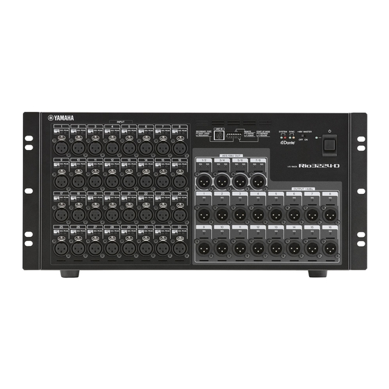
Page 8: Panel Layout(パネルレイアウト
Rio3224-D PANEL LAYOUT (パネルレイアウト) Front Panel(フロントパネル) ui o !0 !1 q [INPUT] Connectors 1–32 q [INPUT] (インプット) 端子 1 ∼ 32 w [+48V] Indicators w [+48V] インジケーター e [SIG] (Signal) Indicators e [SIG] (シグナル) インジケーター r [PEAK] Indicators r [PEAK] (ピーク) インジケーター... - Page 9 Rio3224-D Rear Panel(リアパネル) !4 [PRIMARY]/[SECONDARY] Connectors !4 [PRIMARY] 端子 / [SECONDARY] 端子 !5 [LINK/ACT] Indicators !5 [LINK/ACT] インジケーター !6 [1G] Indicators !6 [1G] インジケーター !7 AC IN Connector !7 AC IN 端子 !8 [FAN] Switch !8 [FAN] スイッチ...
-
Page 10: ■ Circuit Board Layout (ユニットレイアウト
Rio3224-D ■ CIRCUIT BOARD LAYOUT (ユニットレイアウト) DNTE MODULE 32CH DC3216 (ダンテモジュール 32CH) DNTSB SHEET SUPPORT DNTCN (シートサポート) DC FAN MOTOR (DC ファンモーター) DC FAN MOTOR (DC ファンモーター) AESO (OUTPUT 1-8) (OUTPUT 9-16)... - Page 11 Rio3224-D POWER SUPPLY UNIT (電源ユニット) DNTCN HAAD (INPUT 1-8) HAAD (INPUT 9-16) HAAD (INPUT 17-24) HAAD (INPUT 25-32) AC SHIELD ANGLE (AC シールド金具) RTSW PWRSW LEDDA1 (OUTPUT 1-8) LEDDA2 LEDAD1 (INPUT 1-8) (OUTPUT 9-16) LEDAD2 (INPUT 9-16) LEDAESO LEDAD3 (INPUT 17-24)...
-
Page 12: ■ Disassembly Procedure (分解手順
Rio3224-D ■ DISASSEMBLY PROCEDURE (分解手順) Precaution(注意事項) * Install the fi lament tape and the harness clamp in the ※ フィラメントテープ、束線止めは、取り外す前と同じように same way as they were before removal. 取り付けてください。 * Notes on Flat Cable ※ フラットケーブル注意 Contacts are visible from the back. Pay attention 接点が裏面から透けて見えます。コネクタにケーブルの... - Page 13 Rio3224-D Top Cover トップカバー (Time required: About 6 minutes) (所要時間:約 6 分) 1-1. Remove the twelve (12) screws marked [1240]. The 1-1. [1240] のネジ 12 本を外して、左右のラックアング right and left rack angle can then be removed. (Fig. 1) ルを外します。 (図 1)...
- Page 14 Rio3224-D Rear view [1040] [1220] [1220] [1220] [1220] [1220] Top view TOP COVER(トップカバー) [1220] [1220] [1220] Installation reference screw (取付基準ネジ) Fig. 2 (図 2) DC3216 Circuit Board DC3216 シート (Time required: About 7 minutes) (所要時間:約 7 分) 2-1. Remove the top cover. (See procedure 1) 2-1.
- Page 15 Rio3224-D DNTSB Circuit Board, DNTE Module DNTSB シート、ダンテモジュール 32CH 32CH (所要時間:約 7 分) (Time required: About 7 minutes) 3-1. トップカバーを外します。 (1 項参照) 3-1. Remove the top cover. (See procedure 1) 3-2. [1110] のネジ 6 本を外して、DNTSB シートを外し 3-2. Remove the six (6) screws marked [1110]. The ます。...
- Page 16 Rio3224-D Sheet Support シートサポート (Time required: About 7 minutes) (所要時間:約 7 分) 4-1. Remove the top cover. (See procedure 1) 4-1. トップカバーを外します。 (1 項参照) 4-2. Remove the screw marked [1040] on the rear panel. 4-2. リアパネル側の [1040] のネジ 1 本を外します。 ( 図 2)...
- Page 17 Rio3224-D HAAD Circuit Board (INPUT 9–16) HAAD シート (INPUT 9‒16) (Time required: About 13 minutes) (所要時間:約 13 分) 6-1. Remove the top cover. (See procedure 1) 6-1. トップカバーを外します。 (1 項参照) 6-2. Remove the sheet support. (See procedure 4) 6-2. シートサポートを外します。 (4 項参照)...
- Page 18 Rio3224-D AESO Circuit Board AESO シート (Time required: About 9 minutes) (所要時間:約 9 分) 9-1. Remove the top cover. (See procedure 1) 9-1. トップカバーを外します。 (1 項参照) 9-2. Remove the sheet support. (See procedure 4) 9-2. シートサポートを外します。 (4 項参照) 9-3. Remove the eight (8) screws marked [720] and the 9-3.
-
Page 19: Output
Rio3224-D Right view DA ANGLE (DA 金具) (OUTPUT 1-8) (OUTPUT 9-16) [570] x2 Fig. 7 (図 7) LEDAD1 Circuit Board (INPUT 1–8), LEDAD1 シート (INPUT 1‒8)、LED レンズ 3P (所要時間:約 7 分) LED LENS (3P) (Time required: About 7 minutes) 12-1. - Page 20 Rio3224-D LEDAD3 Circuit Board (INPUT 17–24), LEDAD3 シート (INPUT 17‒24)、LED レンズ 3P LED LENS (3P) (所要時間:約 14 分) (Time required: About 14 minutes) 14-1. トップカバーを外します。 (1 項参照) 14-1. Remove the top cover. (See procedure 1) 14-2. シートサポートを外します。 (4 項参照) 14-2. Remove the sheet support. (See procedure 4) 14-3.
- Page 21 Rio3224-D LEDAD4 Circuit Board (INPUT 25–32), LEDAD4 シート (INPUT 25‒32)、LED レンズ 3P LED LENS (3P) (所要時間:約 23 分) (Time required: About 23 minutes) 15-1. トップカバーを外します。 (1 項参照) 15-1. Remove the top cover. (See procedure 1) 15-2. シートサポートを外します。 (4 項参照) 15-2. Remove the sheet support. (See procedure 4) 15-3.
- Page 22 Rio3224-D PWRSW Circuit Board PWRSW シート (Time required: About 8 minutes) (所要時間:約 8 分) 17-1. Remove the top cover. (See procedure 1) 17-1. トップカバーを外します。 (1 項参照) 17-2. Remove the sheet support. (See procedure 4) 17-2. シートサポートを外します。 (4 項参照) 17-3. Remove the escutcheon power switch. (Fig. 4) 17-3.
- Page 23 Rio3224-D Power Supply Unit 電源ユニッ ト (Time required: About 8 minutes) (所要時間:約 8 分) 21-1. Remove the top cover. (See procedure 1) 21-1. トップカバーを外します。 (1 項参照) 21-2. Remove the sheet support. (See procedure 4) 21-2. シートサポートを外します。 (4 項参照) 21-3. Remove the four (4) screws marked [780]. The power 21-3.
- Page 24 Rio3224-D DNTCN Circuit Board DNTCN シート (Time required: About 7 minutes) (所要時間:約 7 分) 22-1. Remove the top cover. (See procedure 1) 22-1. トップカバーを外します。 (1 項参照) 22-2. Remove the four (4) screws marked [970] and the 22-2. [970] の ネ ジ 4 本 と [960] の ネ ジ 1 本 を 外 し て、...
-
Page 25: Lsi Pin Description(Lsi 端子機能表
Rio3224-D LSI PIN DESCRIPTION(LSI 端子機能表) 88E6350R (YD688A00) GIGABIT ETHERNET SWITCHING HUB .............30 AK4101AVQ (X3813B00) DIT (Digital Audio Transmitter) ..............31 AK4396VF-E2 (X8324A00) DAC (Digital to Analog Converter) ............32 AK5385BVF-E2 (X5364B00) ADC (Analog to Digital Converter) ............32 DM9000AEP (X7029A00) LAN CONTROLLER ..................31 LCMXO2280C-3TN144C (YE064B00) CPLD (Complex Programmable Logic Device) .......29... - Page 26 Rio3224-D R8A02032BG ( X8810A00 ) CPU ( SWX02 ) DNTSB: IC001 OUTER OUTER NAME FUNCTION NAME FUNCTION PLL analog ground Ground VSSPLL Wave memory data bus 6 ADC analog input 2 Wave memory data bus 7 ADC analog input 1...
- Page 27 Rio3224-D OUTER OUTER NAME FUNCTION NAME FUNCTION MA15 Wave memory address bus 15 Parallel port A6 MA16 Wave memory address bus 16 Parallel port A7 MA17 Wave memory address bus 17 VCCQ Power supply +3.3 V MA18 Wave memory address bus 18...
- Page 28 Rio3224-D YSS919C-FZ (XZ693C00) DSP7 (Digital Signal Processor) DNTSB: IC401 NAME FUNCTION NAME FUNCTION SIO32 PLLEN PLL enable input (0: PLL unuse, 1: PLL use) /TEST Test mode setting (0: TEST, 1: Normal) SIO33 AVss Analog ground SIO34 PLL filter SIO35...
- Page 29 Rio3224-D LCMXO2280C-3TN144C (YE064B00) CPLD (Complex Programmable Logic Device) DNTSB: IC302 NAME FUNCTION NAME FUNCTION PL2A/LUMO_PLLT_FB_A User programmable pin/Optional feedback (PLL) input. T = true PR20B User programmable pin PL2B/LUMO_PLLC_FB_A User programmable pin/Optional feedback (PLL) input C = complement PR20A User programmable pin...
- Page 30 Rio3224-D 88E6350R (YD688A00) GIGABIT ETHERNET SWITCHING HUB DNTSB: IC503 NAME FUNCTION NAME FUNCTION Column 3 for the LED C3_LED SW_MODE[1] Switch Mode 00=Test mode 01=Reserved Media Dependent Interface [3] P0_MDIN[3] 10=Unmanaged/Forwarding mode 11=CPU Attached/Disable mode P0_MDIP[3] Media Dependent Interface [3]...
- Page 31 Rio3224-D DM9000AEP (X7029A00) LAN CONTROLLER DNTSB: IC118 NAME FUNCTION NAME FUNCTION BGRES Bandgap pin SD13 Power output +2.5 V SD12 DD25 SD11 Processor data bus TP RX input SD10 RXGND RX ground TXGND TX ground Digital power supply +3.3 V...
- Page 32 Rio3224-D AK4396VF-E2 (X8324A00) DAC (Digital to Analog Converter) DA: IC903–906 NAME FUNCTION NAME FUNCTION Digital ground CMOS/TTL level select Digital power supply +3.3 V VREFL Low level voltage reference input Master clock input VREFH High level voltage reference input MCLK...
-
Page 33: Circuit Boards(シート基板図
Rio3224-D CIRCUIT BOARDS(シート基板図) AESO Circuit Board (YD666C0) ............... 34 DA Circuit Board (YD588C0) ..............35 DC3216 Circuit Board (YD667C0) ............36 DNTCN Circuit Board (YD594C0) ............44 DNTSB Circuit Board (YD593C0)............38/39 HAAD Circuit Board (YE625A0) ............40/41 LEDAD1 Circuit Board (YD665C0) ............42 LEDAD2 Circuit Board (YD665C0) ............ -
Page 34: Aeso Circuit Board (Yd666C0)
Rio3224-D AESO Circuit Board Component side(部品側) 2NA-WY68100-1... -
Page 35: Da Circuit Board (Yd588C0)
Rio3224-D Scale: 85/100 DA Circuit Board Component side(部品側) 2NA-WY64350-1... -
Page 36: Dc3216 Circuit Board (Yd667C0)
Rio3224-D DC3216 Circuit Board 2NA-WY68070-1... - Page 37 Rio3224-D 2NA-WY68070-1...
- Page 38 Rio3224-D Scale: 80/100 DNTSB Circuit Board to DA-CN903 (CH9-16) to HAAD-CN901 (CH1-8) to DNTCN-CN101 to DANTE MODULE 64CH to DA-CN902 to LEDAESO-CN401 Component side(部品側) 2NA-WY64760-1...
- Page 39 Rio3224-D Scale: 80/100 DNTSB Circuit Board Pattern side(パターン側) 2NA-WY64760-1...
- Page 40 Rio3224-D HAAD Circuit Board to DNTSB-CN601 to DC3216-CN703 or DNTSB-CN602 or DC3216-CN704 or DNTSB-CN603 or DC3216-CN705 or DNTSB-CN604 or DC3216-CN706 Component side(部品側) 2NA-WY64340-1...
-
Page 41: Haad Circuit Board (Ye625A0)
Rio3224-D HAAD Circuit Board Pattern side(パターン側) 2NA-WY64340-1... -
Page 42: Ledad1 Circuit Board (Yd665C0)
Rio3224-D LEDAD1 Circuit Board LEDAD3 Circuit Board Component side(部品側) LEDAD1: 2NA-WY68000-1 LEDAD3: 2NA-WY67990-1... -
Page 43: Ledad2 Circuit Board (Yd665C0)
Rio3224-D LEDAD2 Circuit Board LEDAD4 Circuit Board Component side(部品側) LEDAD2: 2NA-WY68000-1 LEDAD4: 2NA-WY67990-1... -
Page 44: Ledaeso Circuit Board (Yd665C0)
Rio3224-D LEDAESO Circuit Board Component side(部品側) DNTCN Circuit Board Component side(部品側) LEDAESO: 2NA-WY67990-1 DNTCN: 2NA-WY64770-1... -
Page 45: Ledda1 Circuit Board (Yd665C0)
Rio3224-D LEDDA1 Circuit Board LEDDA2 Circuit Board Component side(部品側) LEDDA1: 2NA-WY68000-1 LEDDA2: 2NA-WY67990-1... -
Page 46: Pwrsw Circuit Board (Yd594C0)
Rio3224-D PWRSW Circuit Board Component side(部品側) RTSW Circuit Board Component side(部品側) PWRSW: 2NA-WY64770-1 RTSW: 2NA-WY64770-1... - Page 47 • NETWORK terminal DIAG startup mode Make settings for the DIP switch and UNIT ID switch of Rio3224-D (subject to test) and Rio3224-D (Test jig). * Turn off the power when setting the DIP switch. If the power is turned on, no setting will be refl ected.
- Page 48 Rio3224-D 1-6. Details of applications Test result is NG Select the item to Test result is OK Version information, etc. are shown. Test items are displayed. individual check. [F1]START : Start a test [F2]PAUSE : Temporarily stops a test The check result in detail is...
- Page 49 Rio3224-D Menu Tool bar Description Folder up Moves to the folder just abo ve the current folder Large Icons Displays items with large icons Small Icons Displays items with small icons View List Displays items as a list Details Displays items as a detailed list...
- Page 50 Rio3224-D 1-7. List of test items * ○:to be checked ×: Not to be checked Test name Outline of test item Judgment Service Checks boot version Auto ○ Checks Program Version. Auto ○ Checks MAC Address. Auto ○ 01 INFO Checks Sheet ID.
- Page 51 2. Put check marks in all checkboxes. 3. Use this to start testing. 1. Check that [Rio3224-D-Service] is selected in the tree window. * If it is not selected, select [Rio3224-D-Service]. 2. Check that all items to be checked are marked with check marks in the list window.
- Page 52 00-11-22-33-44-55 None Serial No. RIO3224D01 Serial number text • In case of failure Sheet ID 0002 (Rio3224-D) Sheet ID The result is displayed in the OUTPUT window as follows. Item Text indication NG: DIP SW ALL OFF 2-2. SWITCH Test NG: DIP SW 1 Contents: Checks the condition of DIP switch.
- Page 53 Rio3224-D 2-3. LED Test 2-4. ETHERNET Test Contents: Checks if the POWER LED lights up. Contents: Checks the Dante Ethernet (Primary/Secondary) port Checks if the LEDs light up in order from left. and rear LED. Checks if all red LEDs light up.
- Page 54 Rio3224-D 2-5. SDRAM Test 2-6. FAN Test Contents: Checks the address bus of SDRAM. Contents: Checks FAN for operation. Checks the data bus of SDRAM. Checks FAN for stop. Preparation (Example of screen) Back up head amp parameters in advance as necessary.
- Page 55 Rio3224-D 2-7. PLLPU Test 2-8. DSP7 Test Contents: Checks the PLLPU register by reading/writing it. Contents: Checks the condition of address bus by writing/ reading the register of DSP7. (Example of screen) Checks the condition of data bus by writing/reading the register of DSP7.
- Page 56 Rio3224-D 2-9. WORD CLOCK Test OUTPUT result Contents: Checks Word Clock. • Normal condition The result is displayed in the OUTPUT window as follows. (Example of screen) Item Text indication Serial OK: SERIAL Dante IN OK: Dante IN Dante OUT OK: Dante OUT •...
- Page 57 Rio3224-D • In case of failure 2-12. ANALOG test Contents: Checks +48V voltage. The result is displayed in the OUTPUT window as follows. Checks GAIN settings. Item Text indication Checks 17 – 32 channels for loopback. +48V ON NG: +48V ON Checks MUTE settings.
- Page 58 17–24ch) to analog OUTPUT (1–16ch) Set the DIP switch to the DIAG mode. No.7 and 8 on, others off. Set the UNIT ID switch to 7. Turn on the power switch of Rio3224-D. INPUT 9–16, 25–32ch → OUTPUT 1–16ch 3-2. through mode Starting method to OUTPUT analog input (9–16, 25–32ch)
- Page 59 1-2-1. インターネッ ト プロ トコル (TCP/IP)のプロパテ ィを 1-5. ディップスイ ッチと UNIT ID スイ ッチの設定と起動 開きます。 • NETWORK 端子ダイアグ起動モード Rio3224-D (検査対象)と Rio3224-D (検査治具)のデ ィ ッ プスイ ッチと UNIT ID スイ ッチを設定します。 ※ ディ ップスイ ッチの設定は電源オフの状態で行ってくださ い。電源オンの状態で変更しても設定が反映されません。 1) デ ィ ップスイ ッチをダイアグモードに設定します。...
- Page 60 Rio3224-D 1-6. アプリケーション説明 q タイ トルバー アプリケーションのタイ トルが表示されます。 w タイ トルボタン ウインドウ操作を行うボタンが表示されます。 ボタンは左から 「最小化」 、 「最大化」 、 「閉じる」です。 e メニューバー メニュー一覧が表示されます。 メニュー詳細は以下の通りです。 メニュー ツールバー ツールバー説明 Save OUTPUT アウ ト プッ トの内容をファイルに保存 File Save log ログの内容をファイルに保存 Exit アプリケーションを終了 Execute 単一検査の実行 Start 検査の開始...
- Page 61 Rio3224-D メニュー ツールバー ツールバー説明 Folder up 1つ上のフォルダへ移動 Large Icons リス トを大きいアイコンで表示 Small Icons リス トを小さいアイコンで表示 View List リス トを一覧で表示 Details リス トを詳細で表示 Options 各種オプションの設定を行います Help About アプリケーションのバージョン情報を表示 r ツールバー i アウトプッ トウインドウ コマンドボタンが表示されます。 実機との通信内容等の文字列が表示されます。 このウインドウは表示/非表示の切り替え、及びフロー フォ ン トの種類及び文字色の変更は [表示] - [ オプション]...
- Page 62 Rio3224-D 1-7. 検査項目一覧 ※ ○:検査する/×:検査しない 検査項目 検査概要 判定 サービス Boot Version 確認。 自動 ○ Program Version 確認。 自動 ○ MAC Address 確認。 自動 ○ 01 INFO Sheet ID 確認。 自動 ○ Serial No. 確認。 自動 ○ CPLD Version 確認。 自動...
- Page 63 ※ 検査対象を絞りたい場合は、検査対象だけにチェック印をつけます。 3. 下記のいずれかの方法で検査を開始します。 • ツールバーの [Start] をクリックします。 • ファ ンクションキーの [START] をクリックします。 • キーボードの [F 1 ] を押します。 • メニューバーの [Test] - [Start] をクリックします。 1-9. 検査終了後のディップスイ ッチ設定方法 1. ディ ップスイ ッチを通常モードに設定します。 全て off 2. Rio3224-D の Power スイ ッチをオフします。...
- Page 64 MAC Address 00-11-22-33-44-55 なし • 故障時 Serial No. RIO3224D01 シリアル番号文字列 アウ ト プッ ト ウインドウへ下記の通り表示します。 Sheet ID 0002 (Rio3224-D) Sheet ID 項目 表示文字列 NG: DIP SW ALL OFF NG: DIP SW 1 2-2. SWITCH 検査 NG: DIP SW 2 内容 DIP SW の状態を検査します。...
- Page 65 Rio3224-D 2-3. LED 検査 2-4. ETHERNET 検査 内容 POWER LED が点灯するか検査を行います。 内容 Dante Ethernet ( Primary/Secondary)ポー ト及びリ LED を左から順に点灯するか検査を行います。 ア LED の検査を行います。 赤の LED が全点灯するか検査を行います。 注意事項 緑の LED が全点灯するか検査を行います。 検査者によって Secondary ポー トのケーブルの抜き差しがあ オレンジの LED が全点灯するか検査を行います。 る為、表示されるダイアログに従って操作を行ってください。 LED が全点灯するか検査を行います。 下記のダイアログが表示されたとき、 Secondaryポー トのケー...
- Page 66 Rio3224-D 2-5. SDRAM 検査 2-6. FAN 検査 内容 SDRAM のアドレスバスの検査を行います。 内容 FAN の動作検査を行います。 SDRAM のデータバスの検査を行います。 FAN の停止検査を行います。 事前準備 〈画面例〉 必要に応じ、ヘッ ドアンプパラメータをバックアップしてくだ さい。 〈画面例〉 出力結果 • 正常時 アウ ト プッ ト ウインドウへ下記の通り表示します。 出力結果 項目 表示文字列 • 正常時 Fan Normal OK: Fan Normal アウ...
- Page 67 Rio3224-D 2-7. PLLPU 検査 2-8. DSP7 検査 内容 PLLPU レジスタの読み書きテス トを実行します。 内容 DSP7 の Register を Write/Read してアドレスバス の良否を検査します。 〈画面例〉 DSP7 の Register を Write/Read してデータバスの 良否を検査します。 DSP7 の Register を Write/Read して Chip Select の良否を検査します。 〈画面例〉 出力結果 • 正常時...
- Page 68 Rio3224-D 2-9. WORD CLOCK 検査 出力結果 内容 WORD CLOCK の検査を行います。 • 正常時 アウ ト プッ ト ウインドウへ下記の通り表示します。 〈画面例〉 項目 表示文字列 Serial OK: SERIAL Dante IN OK: Dante IN Dante OUT OK: Dante OUT • 故障時 アウ ト プッ ト ウインドウへ下記の通り表示します。...
- Page 69 Rio3224-D 2-12. ANALOG 検査 • 故障時 内容 +48V 電圧の検査を行います。 アウ ト プッ ト ウインドウへ下記の通り表示します。 GAIN 設定の検査を行います。 項目 表示文字列 17-32ch のループバック検査を行います。 +48V ON NG: +48V ON MUTE 設定の検査を行います。 +48V OFF NG: +48V OFF バリピッチ (42.336kHz, 100kHz)設定の検査を行い GAIN MAX NG: GAIN M ます。...
- Page 70 Rio3224-D • 故障時 2) Rio3224-D の Power スイ ッチをオフにします。 アウ ト プッ ト ウインドウへ下記の通り表示します。 3-4. ヘッドアンプパラメータ 項目 表示文字列 スルーモード中のヘッ ドアンプ設定は、下記の通り固定とな AES/EBU 96kHz NG: AES/EBU 96kHz ります。 AES/EBU 100kHz NG: AES/EBU VARIPITCH HI AES/EBU 42.336kHz NG: AES/EBU VARIPITCH LO パラメータ名 設定値...
- Page 71 Rio3224-D ■ INSPECTIONS 1. Preparations 2. ANALOG IN/OUT Test 2-1. INPUT 1 – 16 → OUTPUT 1 – 16 1-1. Settings The ANALOG test of the test program is used for the Parameters: Input analog signals from the CHn (n=1–16) input ANALOG IN/OUT characteristic test.
- Page 72 Rio3224-D 2-2. Vari pitch sound signal test B. GAIN MAX Input an analog signal from CH1 INTPUT and measure the 1 Gain (INPUT 1–32) output signal from the CH1 OUTPUT. Input Specifi ed Permissible Input Level Frequency Output Level Range...
- Page 73 Select Sec. PK. Select BW: 700 Hzto100 kHz Check at AES/EBU OUT 1/2 Have test signals generated from the DSP in Rio3224-D and measure the signals output from AES/EBU OUT 1/2 OUTPUT. For the measurement procedure, refer to Test Program [2–13.
- Page 74 Rio3224-D 検査 1. 準備 2. ANALOG IN / OUT 検査 1-1. 設定 2-1. INPUT 1 − 16 → OUTPUT 1 − 16 テストプログラムの ANALOG 検査を使用して、ANALOG 条件 CHn (n= 1 − 16)入力からアナログ信号を入力し、 IN/OUT 特性検査を行います。テス ト プログラム (59 ページ) CHn (n= 1 − 16)出力から出力される信号を計測...
- Page 75 Rio3224-D 2-2. バリピッチ音声信号検査 B. GAIN MAX 1 利得 (INPUT 1 − 32) CH1入力からアナログ信号を入力し、CH1出力から出力 される信号を計測します。 入力周波数 入力レベル 規定出力レベル 許容範囲 1 kHz ‒62 dBu +4 dBu +4 ± 2 dBu 利得 WORD 入力 入力 規定出力 2 歪率 (INPUT 1 − 32) 許容範囲...
- Page 76 4. ファ ンの確認 リアパネルにある FAN HIGH、LOW のスイッチを HIGH 3-1. AES/EBU OUT 側に切り替えたとき、ファンの回転数が速くなり、LOW 側 条件 System Two を使用します。 に切り替えたとき、ファンの回転数が遅くなることを確認し Rio3224-D 内 部 DSP からテスト用 信号を発 生し、 ます。 AES/EBS OUT CHn (n=1−8)出力から出力さ れる信号を計測します。測定手順は、テス ト プログラ ム項目 「2-13 AES/EBU 検査」 (69 ページ) を参照し 5. 出荷時の設定...
- Page 77 Start the application program for updating. When “update.exe” is activated, the screen as shown below will 1-4. Connection Connect the PC and Primary port of Rio3224-D with Ethernet appear. (CAT5e) straight cable. * Only the above connection is required. Do not connect anything to other terminals.
- Page 78 2-10. In case of updating failed If an error occurs during writing or writing is not fi nished after a long time, end the application once, restart Rio3224-D and perform the fi rmware updating procedure from the beginning.
- Page 79 Rio3224-D 2-11. List of errors and warnings Error No. Description Command transmission was failed. (Securement of communication pathway) [ERROR:001] Command transmission failed (to secure communication passage). Command transmission was failed. (Acquisition of communication control authority) [ERROR:002] Command transmission failed (to obtain communication control right).
- Page 80 • PROG 用:¥Firmware¥prog¥RIO_PROG.BIN ア ップデー ト対象のアプリケーションを起動してください。 バージョンが違う場合は、最新にア ップデー トしてください。 update.exe を起動すると下記の画面が表示されます。 1-4. 接続方法 パ ソ コ ン と Rio3224-D の Primary ポ ー ト を Ethernet (CAT5e)ス トレー トケーブルで接続します。 ※ 上記のみを接続し、それ以外の端子には何も接続しない でください。 2-3. アップデート ファーム情報確認 File box 内の 「product name:」 、 「version:」が正しく表示さ...
- Page 81 実機にア ップデー ト ファイルの転送が始まり、FLASH ROM に書き込まれます。 〈画面例〉 2-8. アプリケーション終了 右上の [×] ボタンを押し、アプリケーションを終了します。 2-9. Rio3224-D の電源オフ 1) デ ィ ップスイ ッチを通常モードに設定します。 全て off 2-6. アップデート中 2) Rio3224-D の Power スイ ッチをオフにします。 「updating fi rmware...」と表示され、進行状況もプログレス バーに表示されます。 2-10. アップデート失敗時 書き込み中にエラーが発生した時や、長時間待っても書 き込みが完了しない時は、アプリケーションを一旦終了し、 Rio3224-D を再起動後、ファームウェアアップデートを最初 からやり直します。...
- Page 82 Rio3224-D 2-11. エラー・警告一覧 エラー番号 内容 Command transmission was failed. (Securement of communication pathway ) [ERROR:001] 通信経路確保コマンド送信を失敗しました。 Command transmission was failed. (Acquisition of communication control authority) [ERROR:002] 通信制御権取得コマンド送信に失敗しました。 Command transmission was failed. (Control authority open) [ERROR:003] 制御権開放コマンド送信に失敗しました。 Command transmission was failed.
- Page 83 ドに設定します。 All off 全て off Turn on the power switch of Rio3224-D. 2) Rio3224-D の Power スイ ッチをオンにします。 Operation is the same as when starting in the normal 3) 内部メモリが初期値になること以外は通常モードでの mode (the green LED of the SYSTEM turns on and 起動と同様の動作となります。...
- Page 84 1-4. Connection Using Firmware Update Manager provided by Audinate, Connect the PC and primary port of Rio3224-D with Ethernet execute updating Dante firmware. (Start in the order of Start (CAT5e) straight cable. menu – Program – Audinate – Dnte Firmware Update Manager * Only the above connection is required and nothing –...
- Page 85 When Rio3224-D connected through the network is found, it is indicated in the list of items to be updated. Put a check mark at the left end of Rio3224-D to be updated. Press the [OK] button, and the screen display will be as shown At this time, do not select more than one but execute updating below.
- Page 86 Audinate 社提供の Firmware Update Manager にて Dante 1-4. 接続方法 ファームウェアのア ップデートを実施します (スタート メニュー パ ソ コ ン と Rio3224-D の Primary ポ ー ト を Ethernet ‒ プログラム ‒ Audinate ‒ Dante Firmware Update (CAT5e)ス トレー トケーブルで接続します。 Manager - Dante Firmware Update Manager で起動) 。...
- Page 87 • bkn2_all-x-x-x-xx_Rio3224-D.dnt ( Rio3224-D) (x-x-x-xx はバージョン番号) 。 2-6. アップデート完了 ア ップデー トが完了すると確認のポップア ップが表示されます。 エラーがあった場合は 3. を参照してください。 2-4. デバイスの選択 ネッ トワーク接続された Rio3224-Dが見つかると、 ア ップデー ト対象として一覧表示されます。 対象となる Rio3224-D の左端にチェックをつけます。 [OK]ボタンを押すと以下の画面表示となります (Status この時複数選択はせずに、1 台ずつア ップデー ト作業を行っ 欄に “Update Done”を表示) 。 てください。 2-7. アプリケーションの終了...
- Page 88 Make sure that there is nothing written after “bar-code input:”. • ¥Rio3224-D¥tools¥serbar2¥serbar2.exe * If there is, click on “clear”. 1-4. Connection Connect the PC and Primary port of Rio3224-D with Ethernet (CAT5e) straight cable. * Only the above connection is required. Do not connect anything to other terminals. 2-4.
- Page 89 Press the [X] button at the upper right to end the application If an error occurs during writing or writing is not finished program. after a long time, end the application once, restart Rio3224-D and perform the serial number writing procedure from the beginning again.
- Page 90 シリアル番号入力 ダウンロードし、C ドライブ直下にコピーしてください。 「bar-code input:」の欄に何も書かれていない事を確認しま • ¥Rio3224-D¥tools¥serbar2¥serbar2.exe す。 ※ 書かれていた場合は、 「clear」をクリックします。 1-4. 接続方法 パ ソ コ ン と Rio3224-D の Primary ポ ー ト を Ethernet (CAT5e)ス トレー トケーブルで接続します。 ※ 上記のみを接続し、それ以外の端子には何も接続しない でください。 2-4. シリアル番号書き込み開始 “21”を入力し、続いて Rio 本体のシリアル番号をキーボー ドを使って打ち込み、 「writing」をクリックします。 Rio3224-D 2.
- Page 91 右上の [×] ボタンを押し、アプリケーションを終了します。 書き込み中にエラーが発生した時や、長時間待っても書 き込みが完了しない時は、アプリケーションを一旦終了し、 2-7. Rio3224-D の電源オフ Rio3224-D を再起動後、シリアル番号書き込みを最初から 1) デ ィ ップスイ ッチを通常モードに設定します。 やり直します。 全て off 2) Rio3224-D の Power スイ ッチをオフにします。 2-9. エラー・警告一覧 エラー番号 内容 Command transmission was failed. (Securement of communication pathway ) [ERROR:001] 通信経路確保コマンド送信を失敗しました。 Command transmission was failed.
- Page 92 Rio3224-D ■ STARTING SEQUENCE ● Starting mode (List) Mode Mode transition method Description of operation Normal (Refresh) Started with DIP switches [7][8] set Parameters other than Fs, WC Master are initialized. mode to OFF([5][6] OFF). Normal (Resume) Started with DIP switch [7] set to All parameters have been backed up.
- Page 93 Rio3224-D ● Finishing Sequence Power turned off. IRQ0 power off interruption occurs. (Power off interruption mask) Input/output sound signal muted. Power down (Key Scan) task activated. Checksum in parameter area calculated and stored in Flash ROM. Usually, the power is turned off completely here.
- Page 94 Rio3224-D ■ 起動シーケンス ● 起動モード(一覧) モード モード遷移方法 動作概要 ディップスイッチ [7][8]OFF で起動 通常 (Refresh) モード FS, WC Master 以外のパラメータが初期化される。 ([5][6] は OFF) ディップスイッチ [7]ON、[8]OFF で起動 通常 (Resume) モード 全てのパラメータがバックアップされている。 ([5][6] は OFF) CL 以外の AD8HR 対応のミキサーで Rio をコントロールする際に設定する。 AD8HR モード ディップスイッチ [5]ON、[6]OFF で起動...
- Page 95 Rio3224-D ● 終了シーケンス 電源オフ IRQ0 パワーオフ割り込み発生(パワーオフ割り込みマスク) 入出力の音声信号ミュート パワーダウン (KeyScan) タスク起床 パラメータ領域のチェックサムを計算してFlashROMに保存する。 通常はここで完全に電源がオフになる。 電源が復帰した! パワーオフ割り込みマスク解除 音声信号復帰処理 通常動作...
- Page 96 Rio3224-D ■ MEMORY INITIALIZATION (メモリ初期化) ● Contents of initialization Subject to Subject to initialization (SWX02 or up) initialization (Brooklyn2) Initializing method Brooklyn Brooklyn Gain 2 setting +48V HA Gain GC Gain 2 setting On/Off Freq On/Off Trim Master (other than...
-
Page 97: Parts List
I/O RACK PARTS LIST CONTENTS(目次) OVERALL ASSEMBLY(総組立) ............2 ELECTRICAL PARTS(電気部品) ..........8–43 Notes : DESTINATION ABBREVIATIONS A : Australian model M : South African model B : British model O : Chinese model C : Canadian model P : Blazillian model D : German model Q : South-east Asia model E : European model... - Page 98 Rio3224-D OVERALL ASSEMBLY (総組立)...
- Page 99 Rio3224-D...
- Page 100 Rio3224-D • Left side • Right side...
- Page 101 DESCRIPTION 部 品 名 REMARKS REF NO. QTY RANK OVERALL ASSEMBLY 総 組 立 Rio3224-D OVERALL ASSEMBLY 総 組 立 (WY20790) ZA148000 BOTTOM CHASSIS ボ ト ム シ ャ ー シ 加 工 品 WH917800 RUBBER FOOT ARMSTRONG K29 ゴ...
- Page 102 Rio3224-D PART NO. DESCRIPTION 部 品 名 REMARKS REF NO. QTY RANK WZ880800 CIRCUIT BOARD AESO A E S O シ ー ト (WY68100) EARTH FILM AEO4 ア ー ス フ ィ ル ム A E O 4 (WZ19660) WE774400 BIND HEAD TAPPING SCREW-B 3.0X8 MFZN2B3...
- Page 103 Rio3224-D PART NO. DESCRIPTION 部 品 名 REMARKS REF NO. QTY RANK 1210 WZ346700 TOP COVER BLACK ト ッ プ カ バ ー 塗 装 品 1220 WE87780R BIND HEAD TAPPING SCREW-S 3.0X6 MFZN2B3 S タ イ ト + B I N D...
- Page 104 PART NO. DESCRIPTION 部 品 名 REMARKS REF NO. QTY RANK ELECTRICAL PARTS 電 気 部 品 Rio3224-D WZ880800 CIRCUIT BOARD AESO A E S O シ ー ト (WY68100)(YD666C0) WY643500 CIRCUIT BOARD D A シ ー ト (YD588C0) WY680700 CIRCUIT BOARD DC3216 D...
- Page 105 Rio3224-D PART NO. DESCRIPTION 部 品 名 REMARKS REF NO. QTY RANK C106 WB575000 POLYESTER FILM CAP. (CHIP) 0.0010 50V J RECT. チ ッ プ マ イ ラ ー C107 US064100 CERAMIC CAPACITOR (CHIP) 0.0100 50V K RECT. チ ッ プ セ ラ( B )...
- Page 106 Rio3224-D PART NO. DESCRIPTION 部 品 名 REMARKS REF NO. QTY RANK C704 US061330 CERAMIC CAPACITOR (CHIP) 33P 50V J RECT. チ ッ プ セ ラ( C H ) C705 WB57410R POLYESTER FILM CAP. (CHIP) .00018 50V J RECT. チ ッ プ マ イ ラ ー...
- Page 107 Rio3224-D PART NO. DESCRIPTION 部 品 名 REMARKS REF NO. QTY RANK EM302 VQ76140R EMI FILTER(CHIP) NFM3DCC101U1H3L エ ミ フ ィ ル チ ッ プ EM401 VQ76140R EMI FILTER(CHIP) NFM3DCC101U1H3L エ ミ フ ィ ル チ ッ プ EM402 VQ76140R EMI FILTER(CHIP) NFM3DCC101U1H3L エ...
- Page 108 Rio3224-D PART NO. DESCRIPTION 部 品 名 REMARKS REF NO. QTY RANK R110 RF35639R CARBON RESISTOR (CHIP) 3.9K D 1608 チ ッ プ 抵 抗 R111 RF357100 CARBON RESISTOR (CHIP) 10.0K D 1608 チ ッ プ 抵 抗 R112 RF357100 CARBON RESISTOR (CHIP) 10.0K D 1608...
- Page 109 Rio3224-D PART NO. DESCRIPTION 部 品 名 REMARKS REF NO. QTY RANK R326 RF356300 CARBON RESISTOR (CHIP) 3.0K D 1608 チ ッ プ 抵 抗 R327 RF354820 CARBON RESISTOR (CHIP) 82.0 D 1608 チ ッ プ 抵 抗 R401 RF356300 CARBON RESISTOR (CHIP) 3.0K D 1608...
- Page 110 Rio3224-D PART NO. DESCRIPTION 部 品 名 REMARKS REF NO. QTY RANK R615 RF357200 CARBON RESISTOR (CHIP) 20.0K D 1608 チ ッ プ 抵 抗 R616 RF357200 CARBON RESISTOR (CHIP) 20.0K D 1608 チ ッ プ 抵 抗 R617 RF35718R CARBON RESISTOR (CHIP) 18.0K D 1608...
- Page 111 Rio3224-D DA and DC3216 PART NO. DESCRIPTION 部 品 名 REMARKS REF NO. QTY RANK R913 RD355100 CARBON RESISTOR (CHIP) 100.0 63M J RECT. チ ッ プ 抵 抗 -918 RD355100 CARBON RESISTOR (CHIP) 100.0 63M J RECT. チ ッ...
- Page 112 Rio3224-D DC3216 PART NO. DESCRIPTION 部 品 名 REMARKS REF NO. QTY RANK C202 US065100 CERAMIC CAPACITOR (CHIP) 0.100 50V Z RECT. チ ッ プ セ ラ F C203 WM489900 CERAMIC CAPACITOR (CHIP) 10.0000 35V M KAKU チ ッ プ セ ラ コ ン...
- Page 113 Rio3224-D DC3216 PART NO. DESCRIPTION 部 品 名 REMARKS REF NO. QTY RANK C523 WC37000R ELECTROLYTIC CAP. (CHIP) 220.00 35.0V チ ッ プ ケ ミ コ ン U D C524 UU249220 ELECTROLYTIC CAPACITOR 2200 25.0V FORM. ケ ミ コ ン F W...
- Page 114 Rio3224-D DC3216 PART NO. DESCRIPTION 部 品 名 REMARKS REF NO. QTY RANK EM713 WE05620R EMI FILTER (CHIP) NFM21PC105B1A3D エ ミ フ ィ ル チ ッ プ -716 WE05620R EMI FILTER (CHIP) NFM21PC105B1A3D エ ミ フ ィ ル チ ッ プ...
- Page 115 Rio3224-D DC3216 PART NO. DESCRIPTION 部 品 名 REMARKS REF NO. QTY RANK R108 RD358470 CARBON RESISTOR (CHIP) 470.0K 63M J RECT. チ ッ プ 抵 抗 R109 RD356390 CARBON RESISTOR (CHIP) 3.9K 63M J RECT. チ ッ プ 抵...
- Page 116 Rio3224-D DC3216 and DNTCN/PWRSW/RTSW PART NO. DESCRIPTION 部 品 名 REMARKS REF NO. QTY RANK R449 WW770000 CARBON RESISTOR (CHIP) 2.2K 1W J 5025 チ ッ プ 抵 抗 R502 RD35747R CARBON RESISTOR (CHIP) 47.0K 63M J RECT. チ ッ...
- Page 117 Rio3224-D DNTCN/PWRSW/RTSW and DNTSB PART NO. DESCRIPTION 部 品 名 REMARKS REF NO. QTY RANK RA307 WH213400 RESISTOR ARRAY 47K X 4 抵 抗 ア レ イ RA310 WH213400 RESISTOR ARRAY 47K X 4 抵 抗 ア レ イ RA311 WH205400 RESISTOR ARRAY 22 X 4 抵...
- Page 118 Rio3224-D DNTSB PART NO. DESCRIPTION 部 品 名 REMARKS REF NO. QTY RANK C331 US635100 CERAMIC CAPACITOR (CHIP) 0.100 16V Z RECT. チ ッ プ セ ラ( F ) C332 US662560 CERAMIC CAPACITOR (CHIP) 560P 50V K RECT. チ ッ プ セ ラ( B )...
- Page 119 Rio3224-D DNTSB PART NO. DESCRIPTION 部 品 名 REMARKS REF NO. QTY RANK C566 US635100 CERAMIC CAPACITOR (CHIP) 0.100 16V Z RECT. チ ッ プ セ ラ( F ) C567 US634100 CERAMIC CAPACITOR (CHIP) 0.010 16V K RECT. チ ッ プ セ ラ( B )...
- Page 120 Rio3224-D DNTSB PART NO. DESCRIPTION 部 品 名 REMARKS REF NO. QTY RANK IC306 XY806A0R IC TC7WH14FU(TE12L,F) I C INVERTER IC307 X7285A00 IC TC7SH00FU I C NAND GATE IC308 XR680A00 IC TC7SH08FU(TE85L,JF) I C IC308 X5896A00 IC SN74LVC1G08DCKR I C...
- Page 121 Rio3224-D DNTSB PART NO. DESCRIPTION 部 品 名 REMARKS REF NO. QTY RANK R213 RD454470 CARBON RESISTOR (CHIP) 47.0 63M J RECT. チ ッ プ 抵 抗 R301 RD454220 CARBON RESISTOR (CHIP) 22.0 63M J RECT. チ ッ プ 抵...
- Page 122 Rio3224-D DNTSB and HAAD PART NO. DESCRIPTION 部 品 名 REMARKS REF NO. QTY RANK R589 RD454560 CARBON RESISTOR (CHIP) 56.0 63M J RECT. チ ッ プ 抵 抗 R590 RD454220 CARBON RESISTOR (CHIP) 22.0 63M J RECT. チ ッ...
- Page 123 Rio3224-D HAAD PART NO. DESCRIPTION 部 品 名 REMARKS REF NO. QTY RANK C107 US063100 CERAMIC CAPACITOR (CHIP) 1000P 50V K RECT. チ ッ プ セ ラ( B ) C108 US063100 CERAMIC CAPACITOR (CHIP) 1000P 50V K RECT. チ ッ プ セ ラ( B )...
- Page 124 Rio3224-D HAAD PART NO. DESCRIPTION 部 品 名 REMARKS REF NO. QTY RANK C310 US061470 CERAMIC CAPACITOR (CHIP) 47P 50V J RECT. チ ッ プ セ ラ( C H ) C311 US062220 CERAMIC CAPACITOR (CHIP) 220P 50V J RECT. チ ッ プ セ ラ( S L )...
- Page 125 Rio3224-D HAAD PART NO. DESCRIPTION 部 品 名 REMARKS REF NO. QTY RANK C513 US061470 CERAMIC CAPACITOR (CHIP) 47P 50V J RECT. チ ッ プ セ ラ( C H ) C514 US061220 CERAMIC CAPACITOR (CHIP) 22P 50V J RECT. チ ッ プ セ ラ( C H )...
- Page 126 Rio3224-D HAAD PART NO. DESCRIPTION 部 品 名 REMARKS REF NO. QTY RANK C716 UU268100 ELECTROLYTIC CAPACITOR 100.00 50.0V RX TP ケ ミ コ ン F W C717 US064100 CERAMIC CAPACITOR (CHIP) 0.0100 50V K RECT. チ ッ プ セ ラ( B )...
- Page 127 Rio3224-D HAAD PART NO. DESCRIPTION 部 品 名 REMARKS REF NO. QTY RANK D107 VT53250R DIODE (CHIP) D1F60 1A 600V TP チ ッ プ ダ イ オ ー ド D108 WC36730R DIODE (CHIP) D1F60 1A 600V TP チ ッ プ ダ イ オ ー ド...
- Page 128 Rio3224-D HAAD PART NO. DESCRIPTION 部 品 名 REMARKS REF NO. QTY RANK IC404 X3505A00 IC NJM2068M-D(TE2) I C OP AMP IC405 X3505A00 IC NJM2068M-D(TE2) I C OP AMP IC502 X3505A00 IC NJM2068M-D(TE2) I C OP AMP IC503 XV944A00 IC TC74HC4053AFT(EL) I...
- Page 129 Rio3224-D HAAD PART NO. DESCRIPTION 部 品 名 REMARKS REF NO. QTY RANK R125 WA44950R METAL FILM RESISTOR (CHIP) 8.2K 1/10 D RECT. チ ッ プ 金 皮 抵 抗 R126 WA44950R METAL FILM RESISTOR (CHIP) 8.2K 1/10 D RECT.
- Page 130 Rio3224-D HAAD PART NO. DESCRIPTION 部 品 名 REMARKS REF NO. QTY RANK R243 WA02540R METAL FILM RESISTOR (CHIP) 1.8K 1/10 D RECT. チ ッ プ 金 皮 抵 抗 R244 WA02570R METAL FILM RESISTOR (CHIP) 2.2K 1/10 D RECT.
- Page 131 Rio3224-D HAAD PART NO. DESCRIPTION 部 品 名 REMARKS REF NO. QTY RANK R407 RD257100 CARBON RESISTOR (CHIP) 10.0K 0.1 J RECT. チ ッ プ 抵 抗 R408 VP437600 METAL FILM RESISTOR 270.0 1/4 F AX26 金 属 被 膜...
- Page 132 Rio3224-D HAAD PART NO. DESCRIPTION 部 品 名 REMARKS REF NO. QTY RANK R527 WA02620R METAL FILM RESISTOR (CHIP) 4.7K 1/10 D RECT. チ ッ プ 金 皮 抵 抗 R528 WA02620R METAL FILM RESISTOR (CHIP) 4.7K 1/10 D RECT.
- Page 133 Rio3224-D HAAD PART NO. DESCRIPTION 部 品 名 REMARKS REF NO. QTY RANK R645 WA02570R METAL FILM RESISTOR (CHIP) 2.2K 1/10 D RECT. チ ッ プ 金 皮 抵 抗 R646 RD255220 CARBON RESISTOR (CHIP) 220.0 0.1 J RECT. チ...
- Page 134 Rio3224-D HAAD PART NO. DESCRIPTION 部 品 名 REMARKS REF NO. QTY RANK R809 VP435400 METAL FILM RESISTOR 33.0 1/4 F AX26 金 属 被 膜 抵 抗 R810 VP439800 METAL FILM RESISTOR 2.2K 1/4 F AX26 金 属 被...
- Page 135 Rio3224-D HAAD PART NO. DESCRIPTION 部 品 名 REMARKS REF NO. QTY RANK RY601 VU685600 RELAY DC NA- 5 W-K 5V 2A UC リ レ ー RY602 VU685600 RELAY DC NA- 5 W-K 5V 2A UC リ レ ー RY701 VU685600 RELAY DC NA- 5 W-K 5V 2A UC リ...
- Page 136 Rio3224-D HAAD and LEDAD1/LEDAD2/LEDDA1 PART NO. DESCRIPTION 部 品 名 REMARKS REF NO. QTY RANK X901 WB09320R CERAMIC RESONATOR CSTCE16M0V51-R0 セ ラ ミ ッ ク 振 動 子 WY680100 CIRCUIT BOARD LEDAD1 (LED16) L E D A D 1 シ ー ト...
- Page 137 Rio3224-D LEDAD1/LEDAD2/LEDDA1 and LEDAD3/LEDAD4/LEDAESO/LEDDA2 PART NO. DESCRIPTION 部 品 名 REMARKS REF NO. QTY RANK * LD221 WY781500 LED (CHIP) RED SML-D12U8WT86(Q/R) チ ッ プ L E D PEAK CH1 * LD222 WY781500 LED (CHIP) RED SML-D12U8WT86(Q/R) チ ッ プ...
- Page 138 Rio3224-D LEDAD3/LEDAD4/LEDAESO/LEDDA2 PART NO. DESCRIPTION 部 品 名 REMARKS REF NO. QTY RANK * LD101 WY781600 LED (CHIP) GREEN SML-D12M8WT86(N/P) チ ッ プ L E D SIGNAL CH1 * LD102 WY781600 LED (CHIP) GREEN SML-D12M8WT86(N/P) チ ッ プ L E...
- Page 139 Rio3224-D LEDAD3/LEDAD4/LEDAESO/LEDDA2 PART NO. DESCRIPTION 部 品 名 REMARKS REF NO. QTY RANK R203 RD356220 CARBON RESISTOR (CHIP) 2.2K 63M J RECT. チ ッ プ 抵 抗 R204 RD356470 CARBON RESISTOR (CHIP) 4.7K 63M J RECT. チ ッ プ 抵...
- Page 140 I/O RACK CIRCUIT DIAGRAM CONTENTS (目次) BLOCK DIAGRAM (001-003) (ブロックダイアグラム) ......3-5 GENERAL DIAGRAM (全体図) 001 ....3 DNTSB, Brooklyn2 002 ....4 HAAD, DA 003 ....5 OVERALL CONNECTOR CIRCUIT DIAGRAM (001-002) (総コネクタ接続回路図) ..............6-7 OVERALL CONNECTOR CIRCUIT DIAGRAM 001 ....
- Page 141 Rio3224-D (回路図表記上の注意) (シート間コネクタの読み方について) (信号名) 対応するシート間のコネクタのあるロケーションを示します。 (アルファベットが水平方向、数字が垂直方向) (3桁の数字は信号の行先ページを示します。) (コネクタの接続について) to DNTSB-CN203 <Page 16: D-3> (Page 16 は回路図のページです。) D-3 は対応するシート間のコネクタのあるロケーションを示します。 (アルファベットが水平方向、数字が垂直方向) Note : See parts list for details of circuit board conponent parts. 注:シートの部品詳細は、パーツリストをご参照ください。 ■ WARNING Components having special characteristics are marked and must be replaced with parts having specifi...
-
Page 142: General Diagram(全体図
■ BLOCK DIAGRAM 001 (Rio3224-D) Rio3224-D DNTCN DNTSB JK111, 112 JK504,505 JK101 JK102 IC115 (48P) CN101 CN501 See page 4 (4P) (4P) IC118 (48P) IC503 (129P) IC110 (54P) CN201 CN202 SW201 IC001 DC3216 (3P) (3P) CN205 (13P) X102 X502 X101... -
Page 143: Dntsb, Brooklyn2 002
■ BLOCK DIAGRAM 002 (Rio3224-D) Rio3224-D CN902 (11P) CN901 CN903 (11P) (8P) HAAD CN903 (8P) CN901 (23P) CN901 (11P) CN608 (8P) CN609 (8P) CN605 (11P) CN605 (11P) HAAD DNTSB CN901 (23P) HAAD CN901 (23P) HAAD CN901 (23P) CN601-604 IC401 (208P) -
Page 144: Haad, Da 003
■ BLOCK DIAGRAM 003 (Rio3224-D) Rio3224-D HAAD, DA 28CA1-2001092469-3 ■ BLOCK DIAGRAM 003 (Rio3224-D) -
Page 145: Overall Connector Circuit Diagram 001
■ OVERALL CONNECTOR CIRCUIT DIAGRAM 001 (Rio3224-D) Rio3224-D RTSW DNTCN DNTSB DC3216 PWRSW WIRE HARNESS (VH) (See page 7) Wiring Assembly AC INLET (See page 7) Wiring Assembly INLD32 (See page 7) LEDAD1 HAAD LEDDA1 Wiring Assembly OUTLD32 (See page 7) -
Page 146: Wiring Diagram Of Connector Assembly
■ OVERALL CONNECTOR CIRCUIT DIAGRAM 002 (Rio3224-D) Rio3224-D Note) The pins in the same in the same line are connected to each other. A pin having no destination for connection is not used. Wiring Diagram of Connector Assembly(束線結線表) ■ OVERALL CONNECTOR CIRCUIT DIAGRAM 002 (Rio3224-D) -
Page 147: Aeso Circuit Diagram
■ AESO CIRCUIT DIAGRAM (Rio3224-D) Rio3224-D TRANSCEIVER to DNTSB-CN203 (Page 16: D-3) ■ AESO CIRCUIT DIAGRAM (Rio3224-D) 28CC1-2001090809... -
Page 148: Rear Panel Dante Connector 001
■ CNSW (DNTCN) 001 CIRCUIT DIAGRAM (Rio3224-D) Rio3224-D not installed to DNTSB-CN501 (Page 19: L-3) to DNTSB-JK504 to DNTSB-JK505 (Page 19: S-3) (Page 19: R-3) Rear Panel Dante Connector ■ CNSW (DNTCN) 001 CIRCUIT DIAGRAM (Rio3224-D) 28CC1-2001090814-1... -
Page 149: Front Panel Power Switch 002
■ CNSW (PWRSW) 002 CIRCUIT DIAGRAM (Rio3224-D) Rio3224-D Front Panel Power Switch ■ CNSW (PWRSW) 002 CIRCUIT DIAGRAM (Rio3224-D) 28CC1-2001090814-2... -
Page 150: Front Panel Rotary Switch 003
■ CNSW (RTSW) 003 CIRCUIT DIAGRAM (Rio3224-D) Rio3224-D OR GATE D-FF DECODER to DNTSB-CN104 (Page 15: B-14) TRANSCEIVER TRANSCEIVER not installed TRANSCEIVER Front Panel Rotary Switch ■ CNSW (RTSW) 003 CIRCUIT DIAGRAM (Rio3224-D) 28CC1-2001090814-3... - Page 151 ■ DA CIRCUIT DIAGRAM (Rio3224-D) Rio3224-D not installed not installed to DNTSB-CN608 (Page 20: B-5) to DC3216-CN701 (Page 14: B-2) N.C. DA Converter DNTSB-CN609 DC3216-CN702 (Page 14: B-3) N.C. to DNTSB-CN605 (Page 20: B-4) ■ DA CIRCUIT DIAGRAM (Rio3224-D) (Page 20: B-6)
-
Page 152: Power Detect, Clock Generator, Dc-Dc Converter 001
■ DCSB (DC3216) 001 CIRCUIT DIAGRAM (Rio3224-D) Rio3224-D SYSTEM RESET to POWER SUPPLY UNIT VARIABLE SHUNT REGULATOR INVERTER SWITCHING REGULATOR not installed not installed not installed not installed INVERTER not installed to DNTSB-CN205 (Page 16: C-9) SWITCHING REGULATOR not installed... -
Page 153: Dc-Dc Converter, Linear Regulator 002
■ DCSB (DC3216) 002 CIRCUIT DIAGRAM (Rio3224-D) Rio3224-D SWITCHING REGULATOR not installed to DA-CN001 (Page 12: C-16) REGULATOR +15V SWITCHING REGULATOR not installed to DA-CN001 (Page 12: C-16) REGULATOR -15V SWITCHING REGULATOR not installed REGULATOR +15V SWITCHING REGULATOR not installed... -
Page 154: Dntsb (001-006)
■ DNTSB 001 CIRCUIT DIAGRAM (Rio3224-D) Rio3224-D TRANSCEIVER TRANSCEIVER to LEDAD1-CN101 (Page 24: G-2) CPU (SWX02) to LEDAESO-CN401 TRANSCEIVER (Page 27: H-3) TRANSCEIVER CPU (SWX02) LAN CONTROLLER FLASH MEMORY 32M SYSTEM RESET not installed INVERTER TRANSCEIVER SDRAM 64M to RTSW-CN301... -
Page 155: Cpu 2/2
■ DNTSB 002 CIRCUIT DIAGRAM (Rio3224-D) Rio3224-D to AESO-CN101 (Page 8: K-4) CPU (SWX02) CPU (SWX02) CPU (SWX02) INVERTER not installed not installed to DC3216-CN181 REGULATOR +1.2V (Page 13: H-7) not installed CPU 2/2 ■ DNTSB 002 CIRCUIT DIAGRAM (Rio3224-D) -
Page 156: Cpld 003
■ DNTSB 003 CIRCUIT DIAGRAM (Rio3224-D) Rio3224-D TRANSCEIVER TRANSCEIVER not installed NAND GATE not installed not installed CPLD not installed CPLD ■ DNTSB 003 CIRCUIT DIAGRAM (Rio3224-D) 28CC1-2001087775-3... - Page 157 ■ DNTSB 004 CIRCUIT DIAGRAM (Rio3224-D) Rio3224-D DSP7 REGULATOR +2.5V DSP7 ■ DNTSB 004 CIRCUIT DIAGRAM (Rio3224-D) 28CC1-2001087775-4...
-
Page 158: Dante 005
■ DNTSB 005 CIRCUIT DIAGRAM (Rio3224-D) Rio3224-D GIGABIT ETHERNET SWITCHING HUB not installed not installed not installed not installed to DANTE MODULE 32CH to DNTCN-CN101 (Page 9: F-4) not installed not installed not installed not installed DC-DC CONVERTER DANTE ■ DNTSB 005 CIRCUIT DIAGRAM (Rio3224-D) - Page 159 ■ DNTSB 006 CIRCUIT DIAGRAM (Rio3224-D) Rio3224-D not installed to HAAD-CN901 (ANALOG INPUT CH1–8) (Page 23: P-3) to DA-CN903 (ANALOG OUTPUT CH9–16) (Page 12: R-15) to HAAD-CN901 (ANALOG INPUT CH9–16) (Page 23: P-3) to DA-CN903 (ANALOG OUTPUT CH1–8) (Page 12: R-15)
-
Page 160: Haad (001-003)
■ HAAD 001 CIRCUIT DIAGRAM (Rio3224-D) Rio3224-D MULTIPLEXER OP AMP OP AMP GAIN SETTING CHART Rated Input (定格入力) (dB) OP AMP MULTIPLEXER not installed OP AMP OP AMP Analog Input Characteristics OP AMP Input Level Input Actual Load For Use With... -
Page 161: Head Amp And Ad Converter 002
■ HAAD 002 CIRCUIT DIAGRAM (Rio3224-D) Rio3224-D MULTIPLEXER OP AMP OP AMP OP AMP MULTIPLEXER not installed OP AMP OP AMP OP AMP not installed MULTIPLEXER OP AMP OP AMP OP AMP MULTIPLEXER not installed OP AMP OP AMP OP AMP... - Page 162 ■ HAAD 003 CIRCUIT DIAGRAM (Rio3224-D) Rio3224-D TRANSCEIVER to DNTSB-CN601 (Page 20: J-2) DNTSB-CN602 (Page 20: J-4) DNTSB-CN603 (Page 20: J-6) DNTSB-CN604 (Page 20: J-9) INVERTER CPU (EC) to DC3216-CN703 (Page 14: B-7) DC3216-CN704 (Page 14: B-7) DC3216-CN705 (Page 14: B-9)
- Page 163 ■ LED32 (LEDAD3, LEDAD1) 001 CIRCUIT DIAGRAM (Rio3224-D) Rio3224-D LED DRIVER TRANSCEIVER to DNTSB-CN101 (Page 15: B-3) to LEDAD2-CN201 (Page 25: H-2) LED DRIVER to LEDAD2-CN201 (Page 25: H-2) to LEDAD4-CN201 (Page 25: H-2) Analog Input Indicate LED 28CC1-2001090826-1 ■ LED32 (LEDAD3, LEDAD1) 001 CIRCUIT DIAGRAM (Rio3224-D)
- Page 164 ■ LED32 (LEDAD4, LEDAD2) 002 CIRCUIT DIAGRAM (Rio3224-D) Rio3224-D LED DRIVER TRANSCEIVER to LEDAD1-CN101 (Page 24: H-2) to LEDAD3-CN101 (Page 24: H-2) LED DRIVER to LEDAD3-CN201 (Page 24: H-2) N.C. Analog Input Indicate LED ■ LED32 (LEDAD4, LEDAD2) 002 CIRCUIT DIAGRAM (Rio3224-D)
- Page 165 ■ LED32 (LEDDA2, LEDDA1) 003 CIRCUIT DIAGRAM (Rio3224-D) Rio3224-D TRANSCEIVER LED DRIVER to LEDAESO-CN401 (Page 27: H-4) to LEDDA1-CN301 to LEDDA2-CN301 N.C. Analog Output Indicate LED ■ LED32 (LEDDA2, LEDDA1) 003 CIRCUIT DIAGRAM (Rio3224-D) 28CC1-2001090826-3...
- Page 166 ■ LED32 (LEDAESO) 004 CIRCUIT DIAGRAM (Rio3224-D) Rio3224-D TRANSCEIVER LED DRIVER to DNTSB-CN102 (Page 15: B-5) to LEDDA1-CN301 (Page 26: H-3) AES3 Output Indicate LED ■ LED32 (LEDAESO) 004 CIRCUIT DIAGRAM (Rio3224-D) 28CC1-2001090826-4...