Cisco Nexus 9508 Hardware Installation Manual
Hide thumbs
Also See for Nexus 9508:
- Hardware installation manual (152 pages) ,
- Hardware installation manual (116 pages)
Table of Contents
Advertisement
Cisco Nexus 9508 Switch Site Preparation and Hardware Installation
Guide
First Published: November 21, 2014
Last Modified: May 30, 2014
Americas Headquarters
Cisco Systems, Inc.
170 West Tasman Drive
San Jose, CA 95134-1706
USA
http://www.cisco.com
Tel: 408 526-4000
800 553-NETS (6387)
Fax: 408 527-0883
Text Part Number: OL-30837-01
Advertisement
Table of Contents

Related Manuals for Cisco Nexus 9508


Summary of Contents for Cisco Nexus 9508
- Page 1 Cisco Nexus 9508 Switch Site Preparation and Hardware Installation Guide First Published: November 21, 2014 Last Modified: May 30, 2014 Americas Headquarters Cisco Systems, Inc. 170 West Tasman Drive San Jose, CA 95134-1706 http://www.cisco.com Tel: 408 526-4000 800 553-NETS (6387)
- Page 2 Cisco and the Cisco logo are trademarks or registered trademarks of Cisco and/or its affiliates in the U.S. and other countries. To view a list of Cisco trademarks, go to this URL: www.cisco.com/go/trademarks . Third-party trademarks mentioned are the property of their respective owners. The use of the word partner does not imply a partnership relationship between Cisco and any other company.
-
Page 3: Table Of Contents
Unpacking and Inspecting a New Switch Installing the Bottom-Support Rails Installing a Chassis in a Rack or Cabinet Grounding the Chassis Connecting the Switch to an AC Power Source Cisco Nexus 9508 Switch Site Preparation and Hardware Installation Guide OL-30837-01... - Page 4 Overview of I/O Module Support Accessing an I/O Module Through a Console Overview of Fabric Modules Overview of Power Modes Power Mode Configuration Guidelines Setting the Power Mode Overview of Fan Trays Cisco Nexus 9508 Switch Site Preparation and Hardware Installation Guide OL-30837-01...
- Page 5 Supervisor Module LEDs Fan Tray LEDs Fabric Module LEDs I/O Module LEDs Power Supply LEDs Accessory Kits A P P E N D I X C Accessory Kit Contents Cisco Nexus 9508 Switch Site Preparation and Hardware Installation Guide OL-30837-01...
- Page 6 Contents Cisco Nexus 9508 Switch Site Preparation and Hardware Installation Guide OL-30837-01...
-
Page 7: Preface
Audience, page vii • Document Conventions, page vii • Related Documentation for Cisco Nexus 9000 Series NX-OS Software, page ix • Obtaining Documentation and Submitting a Service Request, page x Audience This publication is for hardware installers and network administrators who install, configure, and maintain Cisco Nexus devices. - Page 8 Means reader take note. Notes contain helpful suggestions or references to material not covered in the Note manual. Means reader be careful. In this situation, you might do something that could result in equipment damage Caution or loss of data. Cisco Nexus 9508 Switch Site Preparation and Hardware Installation Guide viii OL-30837-01...
-
Page 9: Related Documentation For Cisco Nexus 9000 Series Nx-Os Software
SAVE THESE INSTRUCTIONS Related Documentation for Cisco Nexus 9000 Series NX-OS Software The entire Cisco NX-OS 9000 Series documentation set is available at the following URL: http://www.cisco.com/en/US/products/ps13386/tsd_products_support_series_home.html Release Notes The release notes are available at the following URL: http://www.cisco.com/en/US/products/ps13386/prod_release_notes_list.html... -
Page 10: Obtaining Documentation And Submitting A Service Request
Subscribe to What’s New in Cisco Product Documentation, which lists all new and revised Cisco technical documentation as an RSS feed and delivers content directly to your desktop using a reader application. The RSS feeds are a free service. -
Page 11: Overview
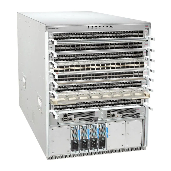
• Overview, page 1 Overview The Cisco Nexus 9508 switch chassis (N9K-C9508) holds the following components: • Supervisor modules (up to two supervisor modules) (N9K-SUP-A) • System controllers (up to two system controller modules) (N9K-SC-A) • I/O modules (up to eight I/O modules) ◦... - Page 12 Overview The following figure shows the hardware features seen from the front of the chassis. Figure 1: Hardware Features on the Front of the Cisco Nexus 9508 Chassis Chassis LEDs 3-kW AC power supplies (up to four if using optical I/O modules with power redundancy;...
- Page 13 The following figure shows the hardware features seen from the rear of the chassis (one fan tray has been removed to show the fabric modules behind the fan trays). Figure 2: Hardware Features on the Rear of the Cisco Nexus 9508 Chassis Grounding pad Fan trays (three—one not shown in order to show...
- Page 14 Overview Overview Cisco Nexus 9508 Switch Site Preparation and Hardware Installation Guide OL-30837-01...
-
Page 15: Preparing The Site
However, if the switch is located in an unusually humid location, you should use a dehumidifier to maintain the humidity within an acceptable range. Cisco Nexus 9508 Switch Site Preparation and Hardware Installation Guide OL-30837-01... -
Page 16: Altitude Requirements
• Strong EMI, especially when it is caused by lightning or radio transmitters, can destroy the signal drivers and receivers in the chassis and even create an electrical hazard by conducting power surges through lines into equipment. Cisco Nexus 9508 Switch Site Preparation and Hardware Installation Guide OL-30837-01... -
Page 17: Grounding Requirements
• Power mode to use and the number of additional power supplies required for that mode You must also ensure that the circuit used for the switch is dedicated to the switch to minimize the possibility of circuit failure. Cisco Nexus 9508 Switch Site Preparation and Hardware Installation Guide OL-30837-01... - Page 18 Step 1 Determine the power requirement for the switch by summing the maximum wattage for each installed module (see the following table). Table 1: Power Requirements for the Cisco Nexus 9508 Switch Modules Component Quantity Maximum...
-
Page 19: Rack And Cabinet Requirements
To correctly install the switch in a cabinet that is located in a hot-aisle/cold-aisle environment, you should fit the cabinet with baffles to prevent exhaust air from recirculating into the chassis air intake. Cisco Nexus 9508 Switch Site Preparation and Hardware Installation Guide OL-30837-01... - Page 20 Stability hazard. The rack stabilizing mechanism must be in place, or the rack must be bolted to the floor Warning before you slide the unit out for servicing. Failure to stabilize the rack can cause the rack to tip over. Cisco Nexus 9508 Switch Site Preparation and Hardware Installation Guide OL-30837-01...
-
Page 21: Clearance Requirements
(if used) or to the edge of the hot aisle (if no cabinet) for module handles Nearest object or inside of cabinet (no side Chassis depth clearance required) Cisco Nexus 9508 Switch Site Preparation and Hardware Installation Guide OL-30837-01... - Page 22 I/O module handles (keep this area clear of rack, cable management, and other components that can prevent full rotation of the ejector levers) No right side clearance required (no airflow on right side) Cisco Nexus 9508 Switch Site Preparation and Hardware Installation Guide OL-30837-01...
-
Page 23: Installing A Chassis
If you are using the combined power mode or power-supply redundancy, you need only one power source. If Note you are using input-source redundancy, you need two power sources. Cisco Nexus 9508 Switch Site Preparation and Hardware Installation Guide OL-30837-01... -
Page 24: Unpacking And Inspecting A New Switch
Step 3 If you notice any discrepancies or damage, send the following information to your customer service representative by email: • Invoice number of the shipper (see the packing slip) Cisco Nexus 9508 Switch Site Preparation and Hardware Installation Guide OL-30837-01... -
Page 25: Installing The Bottom-Support Rails
Be sure there is at least 13 RU (22.75 in [57.8 cm]) of vertical space above the rails to install the chassis (see the following figure). Cisco Nexus 9508 Switch Site Preparation and Hardware Installation Guide OL-30837-01... - Page 26 Figure 4: Positioning the Bottom-Support Rails Position two bottom-support rails at the lowest Allow at least 13 RU (22.7 in [57.8 cm]) for RU on the rack. each chassis. Cisco Nexus 9508 Switch Site Preparation and Hardware Installation Guide OL-30837-01...
-
Page 27: Installing A Chassis In A Rack Or Cabinet
Before You Begin • Verify that the chassis shipment is complete and undamaged. • Verify that a four-post rack or cabinet is installed and secured to the concrete subfloor. Cisco Nexus 9508 Switch Site Preparation and Hardware Installation Guide OL-30837-01... - Page 28 Note You should also have at least two persons to push the chassis and one person to guide the chassis when you slide it into the rack. Cisco Nexus 9508 Switch Site Preparation and Hardware Installation Guide OL-30837-01...
- Page 29 Use at least two persons to push the chassis onto the bottom-support rails and one person to guide the chassis down the center of the rails. Push the lower half of the front side of the chassis so that the back side enters the rack first, and push Cisco Nexus 9508 Switch Site Preparation and Hardware Installation Guide OL-30837-01...
- Page 30 1/4 inch (0.6 cm) below the rails. This action helps to prevent the bottom of the chassis from getting caught on the expansion edges of the bottom-support rails. Cisco Nexus 9508 Switch Site Preparation and Hardware Installation Guide OL-30837-01...
- Page 31 (use a total of 12 screws) What to Do Next After you have secured the chassis to the rack, you can connect the chassis to the data center ground. Cisco Nexus 9508 Switch Site Preparation and Hardware Installation Guide OL-30837-01...
-
Page 32: Grounding The Chassis
• Wire-stripping tool to remove the insulation from the grounding wire. Step 1 Use a wire-stripping tool to remove approximately 0.75 inch (19 mm) of the covering from the end of the grounding wire. Cisco Nexus 9508 Switch Site Preparation and Hardware Installation Guide OL-30837-01... - Page 33 Figure 8: Grounding a Cisco Nexus 9508 Chassis Chassis grounding pad Two M4 screws used to secure the grounding lug to the chassis Cisco Nexus 9508 Switch Site Preparation and Hardware Installation Guide OL-30837-01...
-
Page 34: Connecting The Switch To An Ac Power Source
• The power supplies are installed in the appropriate chassis slots as follows: ◦ For combined power mode or power-supply redundancy mode, the power supplies can be installed in any power supply slot in the chassis. Cisco Nexus 9508 Switch Site Preparation and Hardware Installation Guide OL-30837-01... - Page 35 Verify that the Output Power LED turns on and becomes green. What to Do Next When the power supplies are operating and the switch is fully powered, you are ready to connect the switch to the network. Cisco Nexus 9508 Switch Site Preparation and Hardware Installation Guide OL-30837-01...
- Page 36 Installing a Chassis Connecting the Switch to an AC Power Source Cisco Nexus 9508 Switch Site Preparation and Hardware Installation Guide OL-30837-01...
-
Page 37: Connecting The Switch To The Network
In addition, clean connectors if they are exposed to dust or accidentally touched. Both wet and dry cleaning techniques can be effective; refer to your site's fiber-optic connection cleaning procedures. Cisco Nexus 9508 Switch Site Preparation and Hardware Installation Guide OL-30837-01... -
Page 38: Connecting A Console To The Switch
◦ Network cabling should already be routed to the location of the installed switch. Step 1 Configure the console device to match the following default port characteristics: • 9600 baud • 8 data bits Cisco Nexus 9508 Switch Site Preparation and Hardware Installation Guide OL-30837-01... -
Page 39: Connecting The Management Interface
Route the cable through the central slot in the cable management system. Step 3 Connect the other end of the cable to a 10/100/1000 Ethernet port on a network device. Cisco Nexus 9508 Switch Site Preparation and Hardware Installation Guide OL-30837-01... -
Page 40: Creating The Initial Switch Configuration
IP address, which you must provide. You can perform the other configurations at a later time as described in the Cisco Nexus 9000 Series NX-OS Fundamentals Configuration Guide. You should also know the unique name needed to identify the switch among the devices in the network. -
Page 41: Connecting Interface Ports To The Network
• You must follow the ESD-preventative protocol, such as wearing a grounded ESD wrist strap, whenever handling electronic components. • You must have BASE-T ports available for connection on a 48-port 10/100/1000 Ethernet I/O module installed on the switch. Cisco Nexus 9508 Switch Site Preparation and Hardware Installation Guide OL-30837-01... -
Page 42: Disconnecting A Base-T Port From The Network
Removing and installing a transceiver can shorten its useful life. Do not remove and insert transceivers Caution more often than is absolutely necessary. We recommend that you disconnect cables before installing or removing transceivers to prevent damage to the cable or transceiver. Cisco Nexus 9508 Switch Site Preparation and Hardware Installation Guide OL-30837-01... -
Page 43: Disconnecting Optical Ports From The Network
• Inspect routinely for dust and damage. If you suspect damage, clean and then inspect fiber ends under a microscope to determine if damage has occurred. Cisco Nexus 9508 Switch Site Preparation and Hardware Installation Guide OL-30837-01... - Page 44 Connecting the Switch to the Network Maintaining Transceivers and Optical Cables Cisco Nexus 9508 Switch Site Preparation and Hardware Installation Guide OL-30837-01...
-
Page 45: Managing The Switch
You can display information about the switch hardware and the hardware modules installed in the switch chassis by using the show hardware command. switch# show hardware Cisco Nexus Operating System (NX-OS) Software TAC support: http://www.cisco.com/tac Cisco Nexus 9508 Switch Site Preparation and Hardware Installation Guide OL-30837-01... - Page 46 Part Number is Part Revision is 1 Manufacture Date is Year 17 Week 25 Serial number is SAL17257AHD CLEI code is Module5 empty Module6 empty Module7 empty Module8 empty FM21 empty Cisco Nexus 9508 Switch Site Preparation and Hardware Installation Guide OL-30837-01...
- Page 47 Part Revision is 1 Manufacture Date is Year 17 Week 22 Serial number is SAL17225YFS CLEI code is Module30 Module type is : System Controller 0 submodules are present Cisco Nexus 9508 Switch Site Preparation and Hardware Installation Guide OL-30837-01...
- Page 48 Fan3 ok Model number is N9K-C9508-FAN H/W version is 0.5010 Part Number is 73-15288-05 Part Revision is 2 Manufacture Date is Year 17 Week 14 Serial number is SAL171421SY Cisco Nexus 9508 Switch Site Preparation and Hardware Installation Guide OL-30837-01...
-
Page 49: Displaying The Hardware Inventory For A Switch
Note The following example shows the contents of the first instance of the backplane SPROM. switch# show sprom backplane 1 DISPLAY backplane sprom contents: Common block: Cisco Nexus 9508 Switch Site Preparation and Hardware Installation Guide OL-30837-01... - Page 50 00 00 00 00 00 00 00 00 00 00 00 00 00 00 00 00 00 00 00 00 00 00 00 00 00 00 00 00 00 00 00 00 00 00 Cisco Nexus 9508 Switch Site Preparation and Hardware Installation Guide OL-30837-01...
-
Page 51: Displaying Environmental Information For The Switch
3000.00 W Total Power Output (actual draw) 517.00 W Total Power Input (actual draw) 563.00 W Total Power Allocated (budget) 1728.24 W Total Power Available for additional modules 1271.76 W Cisco Nexus 9508 Switch Site Preparation and Hardware Installation Guide OL-30837-01... -
Page 52: Displaying The Current State Of A Module
• For information on all modules, use the show module command. • For information on a specific supervisor, system controller, I/O, or fabric module, use the show module slot_number command to specify a slot number. Cisco Nexus 9508 Switch Site Preparation and Hardware Installation Guide OL-30837-01... - Page 53 Supervisor Module N9K-SUP-A ha-standby System Controller N9K-SC-A active System Controller N9K-SC-A standby Power-Status Reason ------------ --------------------------- powered-dn Configured Power down powered-dn Configured Power down -------------- ------ 6.1(4.11) 0.1010 6.1(4.11) 0.1010 Cisco Nexus 9508 Switch Site Preparation and Hardware Installation Guide OL-30837-01...
-
Page 54: Displaying Temperatures For A Module
◦ For sensors 1, 3, and 4 (outlet and onboard sensors), the following actions occur: ◦ Displays system messages. ◦ Sends Call Home alerts (if configured). ◦ Sends SNMP notifications (if configured). Cisco Nexus 9508 Switch Site Preparation and Hardware Installation Guide OL-30837-01... -
Page 55: Connecting To A Module
You can connect to any module by using the attach module slot_number command. When the the module prompt appears, you can obtain further details about the module by using module-specific commands in EXEC mode. Cisco Nexus 9508 Switch Site Preparation and Hardware Installation Guide OL-30837-01... -
Page 56: Saving The Module Configuration
A particular switching module is removed and the The configured module information is preserved. same switching module is replaced before you enter the copy running-config startup-config command again. Cisco Nexus 9508 Switch Site Preparation and Hardware Installation Guide OL-30837-01... -
Page 57: Shutting Down Or Starting Up A Module
You can clear the running configuration for a system controller, I/O, or fabric slot (slots 1 to 30) that is not functioning by using the purge module command in EXEC mode. Cisco Nexus 9508 Switch Site Preparation and Hardware Installation Guide OL-30837-01... -
Page 58: Displaying Power Usage Information
Powered-Dn N9K-C9508-FM 0.00 W Powered-Dn N9K-SUP-A 47.00 W 79.92 W Powered-Up N9K-SUP-A 45.00 W 79.92 W Powered-Up N9K-SC-A 12.00 W 60.00 W Powered-Up N9K-SC-A 23.00 W 60.00 W Powered-Up Cisco Nexus 9508 Switch Site Preparation and Hardware Installation Guide OL-30837-01... -
Page 59: Power Cycling A Module
This command will reload module 4. Proceed[y/n]? reloading module 4 ... switch(config)# Rebooting a Switch You can reboot or reload the switch by using the reload command without any options. Cisco Nexus 9508 Switch Site Preparation and Hardware Installation Guide OL-30837-01... -
Page 60: Overview Of Supervisor Modules
Module Terms Usage Description module-27 and module-28 Fixed • Module-27 refers to the supervisor module in chassis slot 27. • Module-28 refers to the supervisor module in chassis slot 28. Cisco Nexus 9508 Switch Site Preparation and Hardware Installation Guide OL-30837-01... -
Page 61: Overview Of I/O Module Support
• 48-port, 1- and 10-Gigabit Ethernet BASE-T with 4-port 10- and 40-Gigabit Ethernet QSFP+ (N9K-X9564TX) • 36-port, 40-Gigabit Ethernet QSFP+ aggregation (N9K-X9636PQ) These modules support the following Cisco Nexus 2000 Series Fabric Extenders (FEXs) using SFP-10G-SR, SFP-10G-LR, and FET transceivers: • Cisco Nexus 2248TP-E FEX •... -
Page 62: Accessing An I/O Module Through A Console
You can troubleshoot bootup problems for an I/O module by accessing the module through its console port. This action establishes a console mode that you must exit in order to use other Cisco NX-OS commands. To attach to the console port for an I/O module, use the attach console module command to specify the module that you need to work with. -
Page 63: Power Mode Configuration Guidelines
The amounts of available and reserve power depend on the power redundancy mode that you specify and the number of power supplies installed in the switch. For each redundancy mode, consider the following: Cisco Nexus 9508 Switch Site Preparation and Hardware Installation Guide OL-30837-01... - Page 64 5.2 kW 3.0 kW 3.0 kW 6.0 kW — Available power exceeds the power requirement for the switch, so the entire switch can power Cisco Nexus 9508 Switch Site Preparation and Hardware Installation Guide OL-30837-01...
- Page 65 5.2 kW 3.0 kW 3.0 kW 3.0 kW 6.0 kW 3.0 kW Available power exceeds the power requirement for the switch, so the entire switch can power up. Cisco Nexus 9508 Switch Site Preparation and Hardware Installation Guide OL-30837-01...
- Page 66 3.0 kW 3.0 kW 3.0 kW 6.0 kW 6.0 kW Available power (6.0 kW) exceeds the power requirement for the switch (5.2 kW), so the entire switch can power up. Cisco Nexus 9508 Switch Site Preparation and Hardware Installation Guide OL-30837-01...
-
Page 67: Setting The Power Mode
• If you remove more than one fan tray at a time, the switch can operate up to three minutes before shutting down. To prevent a shutdown, remove only one fan tray at a time. Cisco Nexus 9508 Switch Site Preparation and Hardware Installation Guide OL-30837-01... -
Page 68: Displaying The Status For The Fan Trays
N9K-C9508-FAN 0.5010 Fan_in_PS1 Fan_in_PS2 None Fan_in_PS3 None Fan_in_PS4 None Fan_in_PS5 None Fan_in_PS6 None Fan_in_PS7 None Fan_in_PS8 None Fan Zone Speed: Zone 1: 0x0 Fan Air Filter : NotSupported switch# Cisco Nexus 9508 Switch Site Preparation and Hardware Installation Guide OL-30837-01... -
Page 69: Replacing Or Installing Modules, Fan Trays, And Power Supplies
Before You Begin • You must wear an electrostatic discharge (ESD) wriststrap or other ESD protective device while handling modules. Cisco Nexus 9508 Switch Site Preparation and Hardware Installation Guide OL-30837-01... - Page 70 Release the lever, hold the front of the module and pull the module all the way out of the chassis. Rotate the ejector lever away from the module. Cisco Nexus 9508 Switch Site Preparation and Hardware Installation Guide OL-30837-01...
- Page 71 Make sure that the other end of the lever engages behind the front of the slot so that the module fully seats onto the connectors on the midplane. e) Screw in the two captive screws to secure the module to the chassis. Tighten the screws to 8 in-lb (0.9 N·m) of torque. Cisco Nexus 9508 Switch Site Preparation and Hardware Installation Guide OL-30837-01...
-
Page 72: Installing Or Replacing A System Controller Module
As you rotate the lever, the module unseats from the midplane and moves slightly forward. d) Use the lever to pull the module a couple of inches (about 5 cm) out of the slot. Cisco Nexus 9508 Switch Site Preparation and Hardware Installation Guide OL-30837-01... - Page 73 Screw in the two captive screws to secure the module to the chassis. Tighten each of these screws to 8 in-lb (0.9 N·m) of torque. f) Verify that the Status (STS) LED turns on and becomes green. Cisco Nexus 9508 Switch Site Preparation and Hardware Installation Guide OL-30837-01...
-
Page 74: Installing Or Replacing An I/O Module
If you are replacing a module that is currently in the chassis, remove the existing module from the chassis by following these steps: a) Disconnect and label each of the interface cables from the module. Cisco Nexus 9508 Switch Site Preparation and Hardware Installation Guide OL-30837-01... - Page 75 Align the back of the module to the guides in the open I/O module slot and slide the module all the way into the slot (see the following figure). Cisco Nexus 9508 Switch Site Preparation and Hardware Installation Guide OL-30837-01...
- Page 76 Verify that the I/O module LEDs turn on and appear as follows: • The Status (STS) LED turns on and becomes green. • For each connected port, the port LED turns on and becomes green or amber. Cisco Nexus 9508 Switch Site Preparation and Hardware Installation Guide OL-30837-01...
-
Page 77: Replacing A Fan Tray
Remove only one fan tray at a time. If you remove more than one fan tray at a time, the switch will shut down Caution within two minutes unless you replace the extra fan trays that you removed within that time. Cisco Nexus 9508 Switch Site Preparation and Hardware Installation Guide OL-30837-01... - Page 78 Hold both handles on the front of the fan tray with both of your hands and pull the fan tray out of the slot. c) Set the fan tray on antistatic material or inside an antistatic bag. Step 3 To install a new fan tray, follow these steps: Cisco Nexus 9508 Switch Site Preparation and Hardware Installation Guide OL-30837-01...
- Page 79 Slide the fan tray all the way into the slot. Cisco Nexus 9508 Switch Site Preparation and Hardware Installation Guide OL-30837-01...
-
Page 80: Replacing A Fabric Module
Number of Fabric Modules Slots to be Filled 1 (Not allowed) N.A. 2 (Not recommended) N.A. 3 (minimum recommended number) 22, 24, and 26 22, 23, 24, and 26 Cisco Nexus 9508 Switch Site Preparation and Hardware Installation Guide OL-30837-01... - Page 81 Remove only one fan tray at a time. If you remove more than one fan tray at a time, the switch will shut down Caution within two minutes unless you replace the extra fan trays that you removed. Cisco Nexus 9508 Switch Site Preparation and Hardware Installation Guide OL-30837-01...
- Page 82 Hold both handles on the front of the fan tray with both of your hands and slide the fan tray off the two rails in the slot. c) Set the fan tray on antistatic material or inside an antistatic bag. Step 4 Remove the fabric module that you are replacing by following these steps: Cisco Nexus 9508 Switch Site Preparation and Hardware Installation Guide OL-30837-01...
- Page 83 Rotate the two handles at least 30 degrees so that the other end of each handle no longer holds the module in the slot (see Callout 2 in the previous figure). Cisco Nexus 9508 Switch Site Preparation and Hardware Installation Guide OL-30837-01...
- Page 84 Rotate the module 90 degrees and lay it flat on an antistatic surface or in an antistatic bag. Step 5 Install the new fabric module by following these steps: Cisco Nexus 9508 Switch Site Preparation and Hardware Installation Guide OL-30837-01...
- Page 85 Be sure that the locking posts fully rotate down into Slide the module all the way into the slot. the module Cisco Nexus 9508 Switch Site Preparation and Hardware Installation Guide OL-30837-01...
- Page 86 (the module will begin to power up as soon as you connect it to an AC power source and the chassis). Step 6 To reinstall the fan tray, follow these steps: Cisco Nexus 9508 Switch Site Preparation and Hardware Installation Guide OL-30837-01...
- Page 87 Slide the fan tray all the way into the slot. Cisco Nexus 9508 Switch Site Preparation and Hardware Installation Guide OL-30837-01...
-
Page 88: Installing A 3-Kw Ac Power Supply
Otherwise, only one power source is required. Step 1 Open the packaging for the new 3-kW AC power supply and inspect the module for damage. Cisco Nexus 9508 Switch Site Preparation and Hardware Installation Guide OL-30837-01... - Page 89 Slide and hold the middle handle on the ejector lever toward the end of the lever. c) Pull on the lever to move the power supply about 2 inches (5 cm) out of the slot. Cisco Nexus 9508 Switch Site Preparation and Hardware Installation Guide OL-30837-01...
- Page 90 Slide the rear end of the power supply all the way toward the end of the lever. into the slot and press the ejector lever toward the front of the power supply to lock it in the slot. Cisco Nexus 9508 Switch Site Preparation and Hardware Installation Guide OL-30837-01...
- Page 91 The power cables for slots 1 through 4 must be connected to one power source and the power cables inslots 5 through 8 must be connected to another power source. i) Verify that the OK LED turns on and eventually becomes green. Cisco Nexus 9508 Switch Site Preparation and Hardware Installation Guide OL-30837-01...
- Page 92 Replacing or Installing Modules, Fan Trays, and Power Supplies Installing a 3-kW AC Power Supply Cisco Nexus 9508 Switch Site Preparation and Hardware Installation Guide OL-30837-01...
-
Page 93: Appendix A System Specifications
5 to 90% (45 to 50% recommended) operating Ambient (noncondensing) 5 to 95% nonoperating Altitude Operating –500 to 13,000 feet (–152 to 4,000 meters) Storage –1,000 to 30,000 feet (–305 to 9,144 meters) Cisco Nexus 9508 Switch Site Preparation and Hardware Installation Guide OL-30837-01... -
Page 94: Switch Dimensions
– Fabric-1 module (N9K-C9508-FM) 9.6 lb (4.4 kg) Fan Trays (N9K-C9508-FAN) 8.3 lb (3.7 kg) Power Supplies — 1 to 8 – 3-kW AC power supply (N9K-PAC-3000W-B) 6.2 lb (2.8 kg) Cisco Nexus 9508 Switch Site Preparation and Hardware Installation Guide OL-30837-01... -
Page 95: Power Requirements For Switch Modules And Fan Trays
The following table lists the maximum amount of power required for each switch module and fan tray. Typically, power consumption is less for each module. Table 3: Power Requirements for the Cisco Nexus 9508 Switch Modules Component Q u a n t i t y... -
Page 96: Transceivers, Connectors, And Cables Used With Each I/O Module
• Cisco Nexus 2248TP-E FEX • Cisco Nexus 2248PQ-E FEX • Cisco Nexus 2232TM-E FEX • Cisco Nexus 2232TM FEX • Cisco Nexus 2232PP FEX • Cisco Nexus 2224TP FEX Cisco Nexus 9508 Switch Site Preparation and Hardware Installation Guide OL-30837-01... - Page 97 108 feet (33 m) 216 feet (66 m) 269 feet (82 m) 2000 984 feet (300 m) SFP-H10GB-CU1M Twinax cable, — — — — 3.3 feet (1 m) passive, 30-AWG cable assembly Cisco Nexus 9508 Switch Site Preparation and Hardware Installation Guide OL-30837-01...
- Page 98 1 The launch power shall be the lesser of the class 1 safety limit or the maximum receive power. Class 1 laser requirements are defined by IEC 60825-1:2001. For the environmental specifications, see the following table. Cisco Nexus 9508 Switch Site Preparation and Hardware Installation Guide OL-30837-01...
-
Page 99: 1000Base-T And 1000Base-X Sfp Transceiver Specifications
I/O modules. The 1000BASE-T transceiver, shown in the following figure, provides an RJ-45 connection for copper cables. Figure 24: 1000BASE-T SFP Transceiver RJ-45 connector Bail clasp shown in the open (unlocked) position Bail clasp shown in the closed (locked) position Cisco Nexus 9508 Switch Site Preparation and Hardware Installation Guide OL-30837-01... - Page 100 1000BASE-LX LC duplex 1310 62.5 1804 feet (550 m) (GLC-LH-SMD) 50.0 1804 feet (550 m) 50.0 1804 feet (550 m) LC duplex 1310 G.652 — 6.2 miles (10 km) Cisco Nexus 9508 Switch Site Preparation and Hardware Installation Guide OL-30837-01...
-
Page 101: Rj-45 Module Connectors
• Supervisor modules ◦ CONSOLE port ◦ MGMT ETH port • Fabric Extenders (Cisco Nexus 2232PP, 2232TM, 2232TM-E, 2248PQ, 2248TP, and 2248TP-E FEXs) ◦ 100/1000 downlink ports Caution To comply with GR-1089 intrabuilding, lightning immunity requirements, you must use a foil twisted-pair (FTP) cable that is properly grounded at both ends. -
Page 102: 3-Kw Ac Power Cord Specifications
Power Cord Illustration Australia and New CAB-AC-16A-AUS 16A, 250 VAC Zealand Peoples Republic of CAB-AC-16A-CH 16A, 250 VAC China Continental Europe CAB-AC-2500W-EU 16A, 250 VAC International CAB-AC-2500W-INT 16A, 250 VAC Cisco Nexus 9508 Switch Site Preparation and Hardware Installation Guide OL-30837-01... - Page 103 America (locking) 200-240 VAC operation Japan and North CAB-7513AC 16A, 250 VAC America 100-120 VAC operation Power distribution unit CAB-C19-CBN 16A, 250 VAC (PDU) Switzerland CAB-ACS-16 16A, 250 VAC Cisco Nexus 9508 Switch Site Preparation and Hardware Installation Guide OL-30837-01...
- Page 104 System Specifications 3-kW AC Power Cord Specifications Cisco Nexus 9508 Switch Site Preparation and Hardware Installation Guide OL-30837-01...
-
Page 105: Leds
Amber Check the Supervisor Module LEDs for more information. Green Fabric modules are all operational. Amber Check the FAB LED description in the Fan Tray LEDs for more information. Cisco Nexus 9508 Switch Site Preparation and Hardware Installation Guide OL-30837-01... -
Page 106: System Controller Leds
This module is not being identified. Green This module is operational. Flashing This module is booting up. amber Flashing Temperature exceeds major alarm threshold. The module is not receiving power. Cisco Nexus 9508 Switch Site Preparation and Hardware Installation Guide OL-30837-01... -
Page 107: Supervisor Module Leds
The management port is linked up. LINK) The management port is not linked up. (management port Green The management port is linked up. ACT) The management port is not linked up. Cisco Nexus 9508 Switch Site Preparation and Hardware Installation Guide OL-30837-01... -
Page 108: Fan Tray Leds
The fabric module is operational. Flashing red The fabric module has a fault. Flashing The fabric module is booting up. amber No power is going to the fabric module. Cisco Nexus 9508 Switch Site Preparation and Hardware Installation Guide OL-30837-01... -
Page 109: I/O Module Leds
The port is disabled by the operator or is not initializing. Flashing orange The port is faulty and disabled. The port is not active or the link is not connected. Cisco Nexus 9508 Switch Site Preparation and Hardware Installation Guide OL-30837-01... -
Page 110: Power Supply Leds
Power supply is installed without a connection to a power source. seconds) then amber Amber Power supply failure—possibly one of the following conditions: • Over voltage • Over current • Over temperature • Power supply fan failure Cisco Nexus 9508 Switch Site Preparation and Hardware Installation Guide OL-30837-01... -
Page 111: Appendix C Accessory Kits
Rack-Mount Kit (N9K-C9508-RMK) 1 kit • 12-24 x 3/4-in. Phillips screws (24) • M6 x 19 mm Phillips screws (24) • Adjustable bottom-support rails (2) RJ-45 rollover cable DB-9F/RJ-45F PC terminal Cisco Nexus 9508 Switch Site Preparation and Hardware Installation Guide OL-30837-01... - Page 112 Cisco Information Packet Not applicable 1-Year Limited Warranty for Hardware If you do not receive a part listed in this document, contact Cisco Technical Support at this URL: Note http://www.cisco.com/warp/public/687/Directory/DirTAC.shtml. If you purchased this product through a Cisco reseller, you might receive additional contents in your kit, such as documentation, hardware, and power cables.
- Page 113 • CAB-AC-C6K-TWLK—power cord, 250-VAC 16A, twist lock, NEMA L6-20 • CAB-C19-CBN—cabinet jumper power cord, 250-VAC, 16A, C20C • CAB-ACS-16—power cord, 16-A, Switzerland • CAB-L520P-C19-US—NEMA L5-20 to IEC-C19, 6 ft, US Cisco Nexus 9508 Switch Site Preparation and Hardware Installation Guide OL-30837-01...
- Page 114 Accessory Kits Accessory Kit Contents Cisco Nexus 9508 Switch Site Preparation and Hardware Installation Guide OL-30837-01...
- Page 115 FEX support chassis LEDs COM1/AUX serial port connecting ports guidelines connectors used with modules console connection grounding requirements console serial port grounding the chassis console settings Cisco Nexus 9508 Switch Site Preparation and Hardware Installation Guide OL-30837-01 IN-1...
- Page 116 Serial number, displaying module state, displaying status service clearance module temperature, displaying SFP+ transceivers module, connecting to show environment command modules, transceivers used for show environment power command Cisco Nexus 9508 Switch Site Preparation and Hardware Installation Guide IN-2 OL-30837-01...
- Page 117 59, 85 transceivers 33, 86 installing 10-Gb SFP+ power requirement care replacing transceivers used with modules supervisor LEDs Cisco Nexus 9508 Switch Site Preparation and Hardware Installation Guide OL-30837-01 IN-3...
- Page 118 Index Cisco Nexus 9508 Switch Site Preparation and Hardware Installation Guide IN-4 OL-30837-01...