Bosch MIC-7130-PB4 Operation Manual
Hide thumbs
Also See for MIC-7130-PB4:
- Quick installation manual (45 pages) ,
- Operation manual (112 pages)

Related Manuals for Bosch MIC-7130-PB4


Summary of Contents for Bosch MIC-7130-PB4
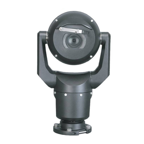
- Page 1 MIC IP starlight 7000 HD MIC-7130-PB4 │ MIC-7130-PW4 │ MIC-7130-PG4 │ MIC-7230-B5 │ MIC-7230-W5 │ MIC-7230-G5 Operation Manual...
-
Page 3: Table Of Contents
About the Configuration Page 13.3 Configuring Audio (Optional) General 14.1 Identification 14.2 User Management 14.3 Date/Time 14.4 Display Stamping 14.5 GB/T 28181 Web Interface 15.1 Appearance 15.2 LIVE Functions Camera Bosch Security Systems Operation Manual 2016.07 | 5.0 | F.01U.291.520... - Page 4 Alarm Rules Interfaces 19.1 Alarm Inputs 19.2 Alarm Outputs Network 20.1 Network Access 20.2 DynDNS 20.3 Advanced 20.4 Network Management 20.5 Multicast 20.6 Image Posting 20.7 Accounts 20.8 IPv4 Filter Service 2016.07 | 5.0 | F.01U.291.520 Operation Manual Bosch Security Systems...
- Page 5 22.2.4 Controlling playback Operation 23.1 Using Intelligent Tracking 23.2 Recommended Use of Your MIC Camera 23.3 Using the Wiper/Washer (Bosch Protocol) 23.4 Using the Wiper/Washer (Pelco Protocol) 23.5 Configuring Settings for IR Illumination 23.6 Uploading a User Logo 23.7 Two-line and Three-line Camera Titles 23.8...
-
Page 6: Safety
Legal Information Copyright This manual is the intellectual property of Bosch Security Systems, Inc. and is protected by copyright. All rights reserved. Trademarks All hardware and software product names used in this document are likely to be registered trademarks and must be treated accordingly. -
Page 7: Important Safety Instructions
– Do not point the camera at the sun. Bosch Security Systems will not be liable for any damage to cameras that have been pointed directly at the sun. –... - Page 8 Camera signal - Protect the cable with a primary protector if the camera signal is beyond 140 feet, in accordance with NEC800 (CEC Section 60). Environmental statement - Bosch has a strong commitment towards the environment. This unit has been designed to respect the environment as much as possible.
- Page 9 – cet appareil doit pouvoir tolérer toutes les interférences auxquelles il est soumit, y compris les interférences qui pourraient influer sur son bon fonctionnement. Bosch Security Systems Operation Manual 2016.07 | 5.0 | F.01U.291.520...
-
Page 10: Important Notices - Illumination Safety
Risk Group 1 – products are safe for most use applications, except for very prolonged exposures where direct ocular exposures may be expected. An example of Risk Group 1 is a domestic battery operated torch (flashlight). 2016.07 | 5.0 | F.01U.291.520 Operation Manual Bosch Security Systems... - Page 11 200 mm 2.19 100 s 200 mm 0.386 Infrared Hazard Hazard 279 mm Distance Retinal Blue Light 10,000 s 200 mm 22.9 100s 200 mm 0.266 Hazard Hazard 2675 mm Distance Bosch Security Systems Operation Manual 2016.07 | 5.0 | F.01U.291.520...
-
Page 12: Customer Support And Service
| Safety MIC IP starlight 7000 HD Customer Support and Service If this unit needs service, contact the nearest Bosch Security Systems Service Center for authorization to return and shipping instructions. Service Centers Telephone: 800-366-2283 or 585-340-4162 Fax: 800-366-1329 Email: cctv.repair@us.bosch.com... -
Page 13: Unpacking
Verify that all the parts listed in the Parts List below are included. If any items are missing, notify your Bosch Security Systems Sales or Customer Service Representative. – Do not use this product if any component appears to be damaged. Please contact Bosch Security Systems in the event of damaged goods. –... -
Page 14: Product Description
VG4-A-PSU1, VG4- 24 VAC (96 W) power supply NPD-9501A 95 W midspan A-PSU2 MIC-ALM-WAS-24 Alarm and washer interface MIC-67SUNSHLD Sunshield (white only) accessory unit 2016.07 | 5.0 | F.01U.291.520 Operation Manual Bosch Security Systems... -
Page 15: Overview Of Installation Steps
Install a Install sunshield? sunshield. Will Cant the camera. camera (Refer to Section 11.) be canted? Configure settings. (Refer to Section 13.) Operate the camera. (Refer to Section 16.) Bosch Security Systems Operation Manual 2016.07 | 5.0 | F.01U.291.520... - Page 16 | Overview of Installation Steps MIC IP starlight 7000 HD IPHelper http://downloadstore.boschsecurity.com/ 2016.07 | 5.0 | F.01U.291.520 Operation Manual Bosch Security Systems...
-
Page 17: Configuration Programming In The Shipping Box
“Inverted,” remove the camera from the box and configure it by following the steps in Configuration Programming on a Temporary Table-top Stand, page 18. 4. Disconnect the wires/cables from the connectors in the base of the camera. Bosch Security Systems Operation Manual 2016.07 | 5.0 | F.01U.291.520... -
Page 18: Configuration Programming On A Temporary Table-Top Stand
(180°). Note that the visor will be near the top of the body of the camera. 6. Disconnect the wires/cables from the connectors in the base of the camera. 2016.07 | 5.0 | F.01U.291.520 Operation Manual Bosch Security Systems... -
Page 19: Mounting Location And Mounting Orientation
If the camera is installed in a highly exposed location where lightning strikes may occur, then Bosch recommends installing a separate lightning conductor within 0.5 m (1.6 ft) of the camera and at least 1.5 m (4.9 ft) higher than the camera. A good earth bonding connection to the camera housing itself will provide protection against damage from secondary strikes. -
Page 20: Select The Mounting Orientation
(370 mm (14.6 in.)) for the camera head to pan. Figure 7.1: Top view of canted MIC7000 illustrating distance of pan clearance The figure below illustrates the tilt range of the camera in upright orientation. 2016.07 | 5.0 | F.01U.291.520 Operation Manual Bosch Security Systems... - Page 21 MIC IP starlight 7000 HD Mounting Location and Mounting Orientation | en 90° 90° 55° 55° Figure 7.2: MIC7000 Tilt Range: 145° each direction; 290° if AutoPivot enabled Bosch Security Systems Operation Manual 2016.07 | 5.0 | F.01U.291.520...
-
Page 22: Overview Of Mounting Options
| Overview of Mounting Options MIC IP starlight 7000 HD Overview of Mounting Options Bosch sells a complete series of mounting brackets that support multiple mounting configurations. The most common type of mounting location is the top of a pole suitable to support CCTV equipment and that provides a robust mounting platform to minimize camera motion and typically has a large base cabinet for mounting ancillary equipment such as power supplies. - Page 23 Other locations for mounting the camera include the top of a building, the side (wall) of a building, the corner of a building, and under the eave of a building. Figure 8.5: Typical Wall mount configuration Figure 8.6: Typical Corner mount configuration Bosch Security Systems Operation Manual 2016.07 | 5.0 | F.01U.291.520...
- Page 24 Figure 8.8: Direct surface mount – camera inverted (MIC + base gasket + IP67 Weatherization/Connector Kit) Notice! Observe all appropriate safety precautions and local building regulations. Refer to the MIC Series Mounting Brackets Installation Guide for installation instructions. 2016.07 | 5.0 | F.01U.291.520 Operation Manual Bosch Security Systems...
-
Page 25: Install The Camera
® Electrical Code (NEC)), Canadian Electrical Code, Part I (also called CE Code or CSA C22.1), and all applicable local codes. Bosch Security Systems, Inc. accepts no liability for any damages or losses caused by incorrect or improper installation. Caution! -
Page 26: Make Connections - Power And Control
The camera can be powered by a network compliant to High Power-over-Ethernet (Bosch’s version of High PoE) using a Bosch model of High PoE Midspans (sold separately). With this configuration, only a single (Cat5e/Cat6e) cable connection is required to view, to power, and to control the camera. -
Page 27: Ethernet Connections
Use the 95 W midspan sold by Bosch. with illuminators) High PoE (60W only for models Use the 60 W midspan sold by Bosch, or a midspan that is compliant to the without illuminators) IEEE 802.3at, class 4 standard. Terminal Connector... -
Page 28: Camera Connections
Note: If the MIC camera will be installed directly to a mounting surface, instead of onto a MIC DCA or a MIC wall mount bracket, Bosch recommends using the MIC7000 IP67 Connector Kit (MICIP67-5pk, sold separately) to protect the connections against moisture and dust particles. -
Page 29: Connect The Camera To The Network
Figure 10.10: MIC7000 IP System Configuration 1 MIC7000 camera 2 IP connection 3 Network switch 4 Networking device (computer, DVR/NVR, etc.) Bosch Security Systems Operation Manual 2016.07 | 5.0 | F.01U.291.520... -
Page 30: Cant The Camera
DCA, with the DCA base upright! It is unstable and might fall and cause bodily injury and/or damage to the camera. Bosch strongly recommends canting the camera after attaching it to a DCA and mounting it in the desired location. - Page 31 1. Remove the yoke cap (item 3 in the figure below) on one yoke arm of the camera, using a torque wrench with ¼ in. drive (item 1, user-supplied) and the supplied spanner tool (item 2). Repeat for the second arm. 1/4” Figure 11.12: Remove yoke caps with spanner tool Bosch Security Systems Operation Manual 2016.07 | 5.0 | F.01U.291.520...
- Page 32 Carefully support the head of the camera while completing the next four (4) steps. 3. Put the screws in a safe place. You will reinstall the screws at step 6. 4. Repeat steps 2 and 3 for the second yoke arm. 2016.07 | 5.0 | F.01U.291.520 Operation Manual Bosch Security Systems...
- Page 33 Do not cant the camera, or let it fall, in the wrong direction! The camera should cant only in the direction indicated in the figure directly below. Figure 11.14: Cant the camera head Bosch Security Systems Operation Manual 2016.07 | 5.0 | F.01U.291.520...
- Page 34 ≈ 15 N m ≈ 17 N m (≈ 11 ft lb) (≈ 12.5 ft lb) ≈ 15 N m ≈ 17 N m (≈ 11 ft lb) (≈ 12.5 ft lb) 2016.07 | 5.0 | F.01U.291.520 Operation Manual Bosch Security Systems...
- Page 35 9. Attach the yoke caps using a torque wrench with ¼ in. drive and the supplied spanner tool. 1/4” 1.4 N m (≈ 12 in. lb) Figure 11.16: Attach yoke caps 10. Canting is complete. Bosch Security Systems Operation Manual 2016.07 | 5.0 | F.01U.291.520...
-
Page 36: Typical System Configurations
5 Data only IP cable (Cat5e/Cat6e) (user-supplied) between midspan and head-end network Note: The total length of Cat5e/Cat6 cable must be less than 100 m (328 ft) between the camera and the head-end system. 2016.07 | 5.0 | F.01U.291.520 Operation Manual Bosch Security Systems... -
Page 37: Typical Configuration With Mic-Alm-Was-24
4 MIC-ALM-WAS-24 enclosure 9 Alarm input / output interface cables (user-supplied) 5 Interface cable for 24 VAC (user- 10 Monitored Normally Open switch for supplied) for MIC-ALM-WAS-24 Supervised Alarm (user-supplied) Bosch Security Systems Operation Manual 2016.07 | 5.0 | F.01U.291.520... -
Page 38: Typical Ip Configuration With Vjc-7000-90
Cat5e/Cat6e = 100 m max. Figure 12.19: Basic configuration with VIDEOJET connect 7000 1 Ethernet (network) cable (Cat5e/Cat6e) (user-supplied) between a Bosch camera and the port labeled PoE on VIDEOJET connect 7000 2 Data-only IP cable (Cat5e/Cat6e) to the head-end network Note: The cable to the head-end also can be fiber optic cable from one of the two SFP slots. -
Page 39: Configuration
You can find notes on using Microsoft Internet Explorer in the online Help in Internet Explorer. If you choose to use a computer running Microsoft Internet Explorer or any of the Bosch software, the computer must conform to the following minimum requirements: –... -
Page 40: Using The Configuration Manager
13.2.1 Using the Configuration Manager Configuration Manager is an optional network utility provided on the Bosch Security Systems Web site. Use the Configuration Manager Manual to make any configuration changes. Note: Depending on the PC network security settings, the user may need to add the new IP address to the browser’s trusted sites list for the controls to operate. -
Page 41: About The Configuration Page
1 hour without power if no central time server is selected. 13.3 Configuring Audio (Optional) Note for MIC7000 cameras only: These options are available only if you have connected a VIDEOJET connect device (VJC-7000-90) to your camera. Bosch Security Systems Operation Manual 2016.07 | 5.0 | F.01U.291.520... -
Page 42: General
BVC or Bosch Video Management Systems Programs. Enter a unique, unambiguous name for the camera in this field. You can use both lines for this. -
Page 43: Date/Time
(switching to summer time and back to normal time). First check whether the correct time zone is selected. If it is not correct, select the appropriate time zone for the system, and click the Set button. Bosch Security Systems Operation Manual 2016.07 | 5.0 | F.01U.291.520... -
Page 44: Display Stamping
Custom option. Or it can be set to Off for no overlay information. Select the desired option from the list. 2016.07 | 5.0 | F.01U.291.520 Operation Manual Bosch Security Systems... - Page 45 Enter the interval (in seconds) between insertions of the digital signature. Signature intervals Select the interval (in seconds) for the signature. Bosch Security Systems Operation Manual 2016.07 | 5.0 | F.01U.291.520...
-
Page 46: Gb/T 28181
Enter the ID of the device. Device port Enter the number of the device port. The default is 5060. Password Enter the appropriate password. Alarm device ID Enter the ID of the alarm device. 2016.07 | 5.0 | F.01U.291.520 Operation Manual Bosch Security Systems... -
Page 47: Web Interface
You can specify the interval at which the individual images should be generated for the M- JPEG image on the LIVE page. JPEG quality You can specify the quality at which the JPEG images appear on the LIVE page. Bosch Security Systems Operation Manual 2016.07 | 5.0 | F.01U.291.520... -
Page 48: Live Functions
Here you can specify whether the section Prepositions of the Live page displays a drop-down box with the list of scenes set in the section Camera > Prepositions and Tours of the Configuration page. 2016.07 | 5.0 | F.01U.291.520 Operation Manual Bosch Security Systems... - Page 49 LIVE page. If necessary, click Browse to find a suitable directory. Video file format Select a file format for the live page display. The MP4 format does not include metadata. Bosch Security Systems Operation Manual 2016.07 | 5.0 | F.01U.291.520...
-
Page 50: Camera
Refer to the following table. Option Additional Input field Not set Cartesian X [m] Y [m] Z [m] Azimuth [°] WGS 84 Latitude Longitude Ground level [m] Azimuth [°] 2016.07 | 5.0 | F.01U.291.520 Operation Manual Bosch Security Systems... -
Page 51: Encoder Profile
Optimized quality are adjusted to ensure that the bit rate is the priority. Profile 7 DSL Optimized Ideal for encoding on a DSL uplink where bit rate limitations are critical. Bosch Security Systems Operation Manual 2016.07 | 5.0 | F.01U.291.520... - Page 52 P-frames, and thus the maximum achievable quality of the P- frames. In the H.264-protocol, the Quantization Parameter (QP) specifies the degree of compression and thus the image quality for every frame. The lower the quantization of the P- 2016.07 | 5.0 | F.01U.291.520 Operation Manual Bosch Security Systems...
-
Page 53: Encoder Streams
Max. frame rate in Camera > Installer Menu to “50/60 fps (up to 1280 x 720 px).” When the option in field The available options in field “Property” for Stream 2 are: “Property” for Stream 1 H.264 MP SD - H.264 MP SD Bosch Security Systems Operation Manual 2016.07 | 5.0 | F.01U.291.520... - Page 54 Profile 6 SD Bit Rate For an SD image, the video bit rate and frame Optimized quality are adjusted to ensure that the bit rate is the priority. 2016.07 | 5.0 | F.01U.291.520 Operation Manual Bosch Security Systems...
-
Page 55: Encoder Regions
Tours. If required, select another region and repeat the steps. To remove a region, select the area and click the waste bin icon. Click Set to apply the region settings. Bosch Security Systems Operation Manual 2016.07 | 5.0 | F.01U.291.520... -
Page 56: Privacy Masks
Inverted. Refer to Installer Menu for orientation settings. Notice! When MIC is canted, Privacy Masks should not be created for scene objects less than 2 m (6 feet) distance from camera. 2016.07 | 5.0 | F.01U.291.520 Operation Manual Bosch Security Systems... -
Page 57: Picture Settings
The degree of color in the video image (HD only). Values range from -14° to 14°; the default is 8°. Intelligent DNR Select On to activate intelligent Dynamic Noise Reduction (DNR) which reduces noise based on motion and light levels. Bosch Security Systems Operation Manual 2016.07 | 5.0 | F.01U.291.520... - Page 58 2% of the image size. This feature is ideal for cameras mounted on a pole or mast, or on another location that shakes frequently. 2016.07 | 5.0 | F.01U.291.520 Operation Manual Bosch Security Systems...
-
Page 59: Lens Settings
Once focused, Auto Focus is inactive until the camera is moved again. – Auto Focus: Auto Focus is always active. – Manual: Auto Focus is inactive. Bosch Security Systems Operation Manual 2016.07 | 5.0 | F.01U.291.520... -
Page 60: Ptz Settings
Determines the behavior of the dome when the control for dome is inactive. Select a time period from the pull-down list (3 sec. - 10 min.). The default setting is 2 minutes. 2016.07 | 5.0 | F.01U.291.520 Operation Manual Bosch Security Systems... - Page 61 Note 1: You can save a total of 15 minutes of recorded actions between the two tours. To record a tour: Click the Start Recording button. The system prompts you to overwrite the existing tour. Bosch Security Systems Operation Manual 2016.07 | 5.0 | F.01U.291.520...
-
Page 62: Prepositions And Tours
SW, W, NW) heading in which the camera is pointing. Notice! The compass feature is not compatible with Bosch’s Intelligent Tracking feature. If Intelligent Tracking is activated, the camera automatically disables the display of the compass heading. Once Intelligent Tracking is deactivated, the camera returns the compass heading to the display. -
Page 63: Preposition Mapping
Stop playback B Compass on Compass off Azimuth on Azimuth off Stabilization auto Stabilization on Stabilization off WDR auto WDR on WDR off Night mode auto Night mode on Night mode off Bosch Security Systems Operation Manual 2016.07 | 5.0 | F.01U.291.520... -
Page 64: Sectors
Place the cursor in the input box to the right of the sector number. Type a title for the sector, up to 20 characters long. To blank the sector, click the check box to the right of the sector title. 2016.07 | 5.0 | F.01U.291.520 Operation Manual Bosch Security Systems... -
Page 65: Miscellaneous
Off: Turns off the wiper. – On: Wiper wipes continuously until deactivated manually, or until it has been on for five minutes (after which the camera will stop the wiper automatically). Bosch Security Systems Operation Manual 2016.07 | 5.0 | F.01U.291.520... -
Page 66: Audio
Select a Pelco AUX number field to map, and then select the appropriate command from the drop-down list. AUX Command Wash/wipe Wiper one shot Wiper continuous Wiper intermittent IR mode 2016.07 | 5.0 | F.01U.291.520 Operation Manual Bosch Security Systems... - Page 67 AUX Command Night mode Night mode auto Alarm output 1 Alarm output 2 Alarm output 3 Alarm output 4 White light Intelligent defog Intelligent tracking Serial mode Select Simplex or Full-duplex. Bosch Security Systems Operation Manual 2016.07 | 5.0 | F.01U.291.520...
-
Page 68: Recording
It is also possible to let the VRM Video Recording Manager control all recording with accessing an iSCSI system. This is an external program for configuring recording tasks for video servers. For further information please contact your local customer service at Bosch Security Systems Inc. -
Page 69: Formatting Storage Media
You can specify whether, in addition to video data and metadata (for example alarms, VCA data and serial data) should also be recorded. Including metadata could make subsequent searches of recordings easier but it requires additional memory capacity. Bosch Security Systems Operation Manual 2016.07 | 5.0 | F.01U.291.520... - Page 70 Notice! For more information, please see the Alarm Task Script Language document and the RCP+ documentation. For the latest version of these documents access your Bosch product catalog on the Internet. 2016.07 | 5.0 | F.01U.291.520...
-
Page 71: Maximum Retention Time
Time periods You can change the names of the recording profiles. Click a profile and then the Rename button. Enter your chosen name and then click the Rename button again. Bosch Security Systems Operation Manual 2016.07 | 5.0 | F.01U.291.520... -
Page 72: Recording Status
The graphic indicates the recording activity of the camera. You will see an animated graphic while recording is taking place. 17.5 Recording Status Details of the recording status are displayed here for information. These settings cannot be changed. 2016.07 | 5.0 | F.01U.291.520 Operation Manual Bosch Security Systems... -
Page 73: Alarm
VIDOS or Bosch Video Management System, you can store a general password here. The camera can use this general password to connect to all remote stations protected with the same password. - Page 74 Auto-connect Select the On option to automatically re-establish a connection to one of the previously specified IP addresses after each reboot, after a connection breakdown or after a network failure. 2016.07 | 5.0 | F.01U.291.520 Operation Manual Bosch Security Systems...
-
Page 75: Vca
If you select the option Silent VCA, then the system creates metadata to facilitate searches of recordings but no alarm is triggered. You cannot change any parameters for this configuration. Bosch Security Systems Operation Manual 2016.07 | 5.0 | F.01U.291.520... - Page 76 Notice! Additional analysis algorithms with comprehensive functions such as IVMD and IVA are available from Bosch Security Systems Inc. If you select one of these algorithms, you can set the corresponding parameters here directly. You can find information on this in the relevant documents on the product CD supplied.
- Page 77 This allows you to avoid false alarms triggered by short-term changes, for example cleaning activities in the direct field of vision of the camera. Bosch Security Systems Operation Manual 2016.07 | 5.0 | F.01U.291.520...
- Page 78 Appearing edges Select this option if the selected area of the reference image includes a largely homogenous surface. If structures appear in this area, then an alarm is triggered. 2016.07 | 5.0 | F.01U.291.520 Operation Manual Bosch Security Systems...
-
Page 79: Virtual Masks
Notice! First set up normal audio transmission before you configure the audio alarm here (see Audio). Audio alarm Select On if you want the device to generate audio alarms. Bosch Security Systems Operation Manual 2016.07 | 5.0 | F.01U.291.520... -
Page 80: Alarm E-Mail
Click the checkbox to specify that JPEG images are sent from the camera. An enabled video input is indicated by a check mark. Destination address Enter the e-mail address for alarm e-mails here. The maximum address length is 49 characters. 2016.07 | 5.0 | F.01U.291.520 Operation Manual Bosch Security Systems... -
Page 81: Alarm Task Editor
IVA/MOTION+: If you select this option, then an alarm will begin when IVA or motion detection is activated. – Connection: If you select this option, then an alarm will begin when an attempt is made to access the camera’s IP address. Bosch Security Systems Operation Manual 2016.07 | 5.0 | F.01U.291.520... - Page 82 50 is set to either of the following values: ) – ”[camera name] - IO“ (for a camera connected to MIC-ALM-WAS-24) – “[camera name] – VJC-7000” (for a camera connected to VJC-7000-90) 2016.07 | 5.0 | F.01U.291.520 Operation Manual Bosch Security Systems...
-
Page 83: Interfaces
Bistable. If you wish an alarm-activated siren to sound for ten seconds, for example, select 10 s. Output name Enter a name for the alarm output. Toggle Click the button to test the relay / output connection. Bosch Security Systems Operation Manual 2016.07 | 5.0 | F.01U.291.520... -
Page 84: Network
If a DHCP server is employed in the network for the dynamic assignment of IP addresses, you can activate acceptance of IP addresses automatically assigned to the camera. Certain applications (Bosch Video Management System, Archive Player, Configuration Manager) use the IP address for the unique assignment of the unit. If you use these... - Page 85 Select the Ethernet link type for the ETH interface. Options are: – Auto – 10 Mbps HD (half duplex) – 10 Mbps FD (full duplex) – 100 Mbps HD (half duplex) Bosch Security Systems Operation Manual 2016.07 | 5.0 | F.01U.291.520...
-
Page 86: Dyndns
20.3 Advanced The settings on this page are used to implement advanced settings for the network. Operation The operation mode determines how the camera communicates with Cloud-based Security and Services. 2016.07 | 5.0 | F.01U.291.520 Operation Manual Bosch Security Systems... -
Page 87: Network Management
If you wish to send SNMP traps automatically, enter the IP addresses of one or two required target units here. SNMP traps You can select which traps are to be sent. Click Select. A list is opened. Bosch Security Systems Operation Manual 2016.07 | 5.0 | F.01U.291.520... -
Page 88: Multicast
The multicast address can be the same for multiple streams. However, it will be necessary to use a different port in each case so that multiple data streams are not sent simultaneously using the same port and multicast address. 2016.07 | 5.0 | F.01U.291.520 Operation Manual Bosch Security Systems... -
Page 89: Image Posting
You can select how file names will be created for the individual images that are transmitted. – Overwrite The same file name is always used and any existing file will be overwritten with the current file. Bosch Security Systems Operation Manual 2016.07 | 5.0 | F.01U.291.520... -
Page 90: Accounts
Enter the exact path on which you wish to post the images on the server. To browse for the correct path, click the Browse button to the right. Maximum bit rate Enter the maximum bit rate for the JPEG images (in kbps). 2016.07 | 5.0 | F.01U.291.520 Operation Manual Bosch Security Systems... -
Page 91: Ipv4 Filter
IP Address 1 / 2 Enter the IPv4 address that you want to allow or block Mask 1 / 2 Enter the subnet mask for the appropriate IPv4 address. Bosch Security Systems Operation Manual 2016.07 | 5.0 | F.01U.291.520... -
Page 92: Service
The installation code of the unit is also displayed here. 21.3 Certificates Usage list HTTPS server Select the default certificate for the HTTPS server. 2016.07 | 5.0 | F.01U.291.520 Operation Manual Bosch Security Systems... -
Page 93: Diagnostics
Click the REFRESH button to reload log data. 21.5 System Overview This window is for information only and cannot be modified. Keep this information at hand when seeking technical support. Bosch Security Systems Operation Manual 2016.07 | 5.0 | F.01U.291.520... - Page 94 | Service MIC IP starlight 7000 HD Select the text on this page with a mouse and copy it so that it can be pasted into an e-mail if required. 2016.07 | 5.0 | F.01U.291.520 Operation Manual Bosch Security Systems...
-
Page 95: Operation Via The Browser
Note: If the preposition is already stored, a dialog box displays the message, “Overwrite current preposition?” Click OK to overwrite, or click Cancel to cancel the operation. Click to display the selected preposition in the video image. Bosch Security Systems Operation Manual 2016.07 | 5.0 | F.01U.291.520... -
Page 96: Aux Control
The icon lights up and displays a moving graphic to indicate a running recording. If no recording is taking place, a static icon is displayed. 2016.07 | 5.0 | F.01U.291.520 Operation Manual Bosch Security Systems... -
Page 97: Saving Snapshots
– if the CPU load is too big, change the VCA settings, – if the network load is too big, change the encoder profile to reduce bitrate. Bosch Security Systems Operation Manual 2016.07 | 5.0 | F.01U.291.520... -
Page 98: Playback
Select the playback speed using the speed regulator – Jump to start of active sequence or to previous sequence – Jump to start of the next video sequence in the list 2016.07 | 5.0 | F.01U.291.520 Operation Manual Bosch Security Systems... -
Page 99: Operation
The camera automatically disables the display of compass headings. Once Intelligent Tracking is set to Off, the camera resumes display of the compass heading. Refer to PTZ Settings, page 60 for details of the Compass feature. Bosch Security Systems Operation Manual 2016.07 | 5.0 | F.01U.291.520... - Page 100 Note: If you do not see these controls on the LIVE page, ensure that the Show ‘Tracking’ option is enabled on the LIVE Functions page. Refer to LIVE Functions, page 48. – Off: Disables Intelligent Tracking. 2016.07 | 5.0 | F.01U.291.520 Operation Manual Bosch Security Systems...
- Page 101 The camera will restart tracking if a target starts moving in the same area where the initial target stopped moving or if the camera detects an object moving along the last known trajectory. Bosch Security Systems Operation Manual 2016.07 | 5.0 | F.01U.291.520...
-
Page 102: Recommended Use Of Your Mic Camera
The tour should also include at least 10° of tilt movement. Preset Tours For scenarios that require the camera to be in continuous motion for most of the day, Bosch recommends that you set the camera in Preset Tour mode, moving between a desired set of presets. -
Page 103: Using The Wiper/Washer (Bosch Protocol)
MIC IP starlight 7000 HD Operation | en 103 23.3 Using the Wiper/Washer (Bosch Protocol) The "predefined position" for the wash/wipe function is preset 62. The installer must define preset 62 (preferably where the washer nozzle is located and can direct washer fluid towards the camera window) before using the wiper/washer function. -
Page 104: Using The Wiper/Washer (Pelco Protocol)
If you prefer not to see this freeze frame, you can turn off the Freeze Frame on Preposition in the PTZ Setup menu. 2016.07 | 5.0 | F.01U.291.520 Operation Manual Bosch Security Systems... -
Page 105: Configuring Settings For Ir Illumination
Height and width must not exceed 128 pixels. – Color depth must be 8 bit (256 color bitmap). Upload the Logo File If necessary, open the browser. Click Configuration. Click General. Select Display Stamping. Bosch Security Systems Operation Manual 2016.07 | 5.0 | F.01U.291.520... -
Page 106: Two-Line And Three-Line Camera Titles
Day Mode. Toggle the text colors in the following sequence: White- >Yellow->Violet->Red->Cyan->Green->Blue->White. – Using the command AUX OFF-77-ENTER, users can set the color again to the default white. 2016.07 | 5.0 | F.01U.291.520 Operation Manual Bosch Security Systems... - Page 107 – The X or XX designates the compass direction that updates automatically as the camera pans. A identifies “North,” “South,” “East,” or West.” AA identifies “Northeast,” “Northwest,” “Southeast,” or “Southwest.” Bosch Security Systems Operation Manual 2016.07 | 5.0 | F.01U.291.520...
-
Page 108: Azimuth, Elevation, And Compass Directions
Azimuth Zero point. Notice! Bosch recommends that only the installer calibrate the Azimuth Zero point. A recalibration to the Azimuth Zero point may cause inaccurate compass headings. Set the Azimuth Zero point: Determine the North compass heading, then move the camera to that position. -
Page 109: Troubleshooting
Test your camera with another power supply. intermittently No OSD messages appear. Bosch’s Video SDK is required. Video management software from third parties does not use the SDK. Nothing appears on the screen. Are the power cord and line connection between the camera and monitor made properly? The image on the screen is dim. - Page 110 – Check that the maximum Ethernet cable distance has not been exceeded. If O.K., then: – Restore all camera settings. Background is too bright to see Turn on backlight compensation. subject. 2016.07 | 5.0 | F.01U.291.520 Operation Manual Bosch Security Systems...
- Page 111 (especially on the yoke arms). – If there is obvious and severe damage, stop using the camera and contact your Bosch Service Center for assistance. – If no damage is evident, complete one of the following steps: a) Cycle the power on the camera.
-
Page 112: Maintenance
No User-serviceable Parts Except for the external wiper blade, the device contains no user-serviceable parts. Contact your local Bosch service center for device maintenance and repair. In the event of failure, the device should be removed from site for repair. -
Page 113: Decommissioning
26.2 Disposal Disposal Your Bosch product has been developed and manufactured using high- quality materials and components that can be reused. This symbol means that electronic and electrical devices that have reached the end of their working life must be disposed of separately from household waste. -
Page 114: Technical Data
114 en | Technical data MIC IP starlight 7000 HD Technical data For product specifications, see the datasheet for your camera, available on the appropriate product pages of the Online Product Catalog at www.boschsecurity.com. 2016.07 | 5.0 | F.01U.291.520 Operation Manual Bosch Security Systems... -
Page 115: Keyboard Commands
MIC IP starlight 7000 HD Keyboard Commands | en 115 Keyboard Commands 28.1 Bosch Protocol AUX Keyboard Commands (Bosch Protocol) Note: * denotes a Locked command. Function Command Command Description On/Off Scan 360° / Auto Pan Activates /deactivates Autopan without limits. - Page 116 Focus Correction when IR illuminators turn on/ off. On/Off White light illumination On–Turns on White lights. Off–Turns off White lights. On/Off Alarm Rule Activation/ On–Enables all alarm rules. Deactivation Off–Disables all alarm rules. 2016.07 | 5.0 | F.01U.291.520 Operation Manual Bosch Security Systems...
- Page 117 Focus Polarity On–Reverse Off–Normal On/Off Iris Polarity On–Reverse Off–Normal On/Off Set Azimuth Zero Point / Sets the zero degree pan position. Recalibrate Azimuth Compass Refer to Azimuth, Elevation, and Compass Directions. Bosch Security Systems Operation Manual 2016.07 | 5.0 | F.01U.291.520...
- Page 118 Forces the camera to complete the power on boot sequence. AUTODOME cameras will complete “Finding Home”. Washer Activate washer. “1-99” Pre-position Programming Set ##–Programs a preset view. Shot “1-99” Pre-position Recall Shot ##–Recall programmed preset. 2016.07 | 5.0 | F.01U.291.520 Operation Manual Bosch Security Systems...
-
Page 119: Pelco Protocol
ZOOM In ZOOM Out Focus Far Focus Near Auto Iris Manual Iris Auto Pan NON-PTZ Pelco D Commands Command Description 33 – Preset Action = Press Pans the AutoDome 180° (Flip) Bosch Security Systems Operation Manual 2016.07 | 5.0 | F.01U.291.520... - Page 120 Action=Press and hold (for 2 seconds) 96 – Preset Action=Press Stops a scan 97 – Preset Action =Press Initiates FastAddress process (Pelco Random Scan) 99 – Preset Action=Press Initiates an AutoScan 2016.07 | 5.0 | F.01U.291.520 Operation Manual Bosch Security Systems...
- Page 122 Bosch Sicherheitssysteme GmbH Bosch Security Systems, Inc Robert-Bosch-Ring 5 1706 Hempstead Road 85630 Grasbrunn Lancaster, PA, 17601 Germany www.boschsecurity.com © Bosch Sicherheitssysteme GmbH, 2016...