Table of Contents
Advertisement
Advertisement
Table of Contents

Related Manuals for Samsung SSA-S3010


Summary of Contents for Samsung SSA-S3010
-
Page 1: User Manual
SSA-S3010 SSA-S3011 SSA-S3020 SSA-S3021 SSA-S3040 SSA-S3041 Standalone Biometric Access Controller user manual imagine the possibilities Thank you for purchasing this Samsung product. To receive more complete service, please visit our website. www.samsungsecurity.com... -
Page 2: Safety Information
If this product fails to operate normally, contact the nearest service center. Never disassemble or modify this product in any way. (SAMSUNG is not liable for problems caused by unauthorized modifi cations or attempted repair.) . When cleaning, do not spray water directly onto parts of the product. Doing so may cause fi re or electric shock. -
Page 3: Important Safety Instructions
Avoid aiming the controller directly towards extremely bright objects such as sun. Apparatus shall not be exposed to dripping or splashing and no objects fi lled with liquids, such as vases, shall be placed on the apparatus. The Mains plug is used as a disconnect device and shall stay readily operable at any time. FCC Statement Caution : Any changes or modifi... -
Page 4: Table Of Contents
contents PRODUCT INTRODUCTION Features What’s included At a glance Cable Color Scheme Cable Selection INSTALLATION AND EXTERNAL Installing the rear template Connecting the termination resistor and CONNECTION diode Bypass Diode Connection Earth-grounding the communication cables I/O Connection External Reader Connection Communication Line Connection INITIALIZATION Initializing the system... - Page 5 USER MANAGEMENT Registering ID in Quick mode Registering the ID To delete ID Viewing the ID list To check the number of registered IDs To remove all registered IDs To check the number of registered fi ngerprints To remove the master IDs Duress Mode Door Open Alarm Time Setup Arm/Disarm...
- Page 6 contents Event Memory Setup ADDITIONAL FEATURES ID Display WIEGAND Output Setup Voice Volume Setup One Time Read Version Check Input Test Output Test LCD Test Keypad Test READER Test Memory Test Communication Test Fingerprint Module Version Check Input Type Setup OTHER INFORMATION Menu Structure Default Settings...
- Page 7 product introduction FEATURES State-of-the-art Access Controller This product is a state-of-the-art access controller that is optimal for time and attendance management, and provides 4 input ports and 2 2Form-C relay outputs along with 2 TTL output ports, RS-232/RS-485 and TCP/IP ports to meet the high-level security system requirements and various customer needs.
- Page 8 product introduction External I/O Pins SSA-S30XX has 4 input pins and 4 output pins installed(2 relay and 2 TTL outputs) The input pins can receive signals from the Exit button and the Door Contact sensor, while the two relays can be connected to the Door Lock and the alarm device.
-
Page 9: What's Included
WHAT’S INCLUDED Check if the following items are included in the product package. CABLE: 2PIN Connector (X 1) 3PIN Connector (X 1) Main Unit Wall Mount 4PIN Connector (X 1) 5PIN Connector (X 1) 6PIN Connector (X 1) 8PIN Connector (X 1) 3.5 X 40mm screws (X 4) Diode (X 2) Resistor (X 4) -
Page 10: Front Panel
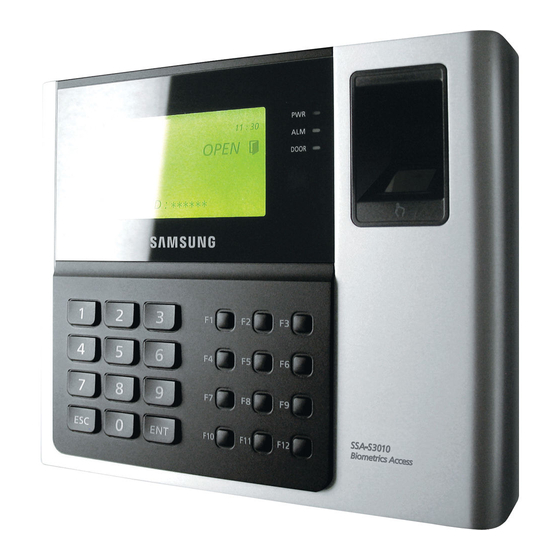
product introduction AT A GLANCE Front Panel This module displays the operation status of the product. Fingerprint Scanner Fingerprint scanner module. The red indicator turns on when the product turns on. System Status LED The red indicator turns on when relay #1 becomes active. The yellow indicator turns on when relay #2 becomes active. -
Page 11: Rear Panel
Rear Panel RJ45 Connector Used in TCP/IP communications. Used in TCP/IP communications. Tamper Switch Tamper switch. Fixing Hole Hole for a fi xing screw. 2-pin Connector Can be connected to the power cable. 3-pin Connector Preliminary connector for extension. 6-pin Connector Can be connected to the I/O cable. -
Page 12: Cable Color Scheme
product introduction CABLE COLOR SCHEME ❖ 2-PIN Connector I/O Pins Signal Cable Color Power (+12V) DC +12V Earth-grounding GND (-) Black ❖ 3-PIN Connector I/O Pins Signal Cable Color RESERVED 1 Pink with White Stripes RESERVED 2 Sky Blue with White Stripes RESERVED 3 Black ❖... -
Page 13: Cable Selection
❖ 4-PIN Connector I/O Pins Signal Cable Color RESERVED 1 Orange with Red Stripes RESERVED 2 Orange with Black Stripes RESERVED 3 Blue RESERVED 4 Brown ❖ TCP/IP RJ45 Connector CABLE SELECTION Description Cable Type Cable Type Product Power (DC12V) Belden #9409, 18 AWG, 2 Conductor, Unshielded Belden #9409, 18 AWG, 2 Conductor, Unshielded This product... - Page 14 installation and external connection INSTALLING THE WALL MOUNT Follow the instructions below to install the wall mount. Place the wall mount on the installation point and mark the 4 holes for the screws. Drill at least 4 of 6-32 holes. Drill a 1/2”...
-
Page 15: Bypass Diode Connection
CONNECTING THE TERMINATION RESISTOR AND DIODE A resistor is inserted for line’s impedance matching to prevent distortion and reduction in RS-422 or RS-485 long distance data communications, which is referred to as termination resistor. Note that termination resistors of lower than 90— are not allowed, neither more than one termination resistor is accepted for the communications system. -
Page 16: Earth-Grounding The Communication Cables
installation and external connection EARTH-GROUNDING THE COMMUNICATION CABLES We recommend you to use a proper grounding system for the communication cables. The best grounding method is to earth-ground the shield wire of the communication cable. However, earth-grounding the communication cable isn’t that easy, apart from the cost increase. There are three grounding points available for installation: 1. -
Page 17: I/O Connection
I/O CONNECTION Input Connection Mon 01 / 01 / 2010 10 : 30 : 20 Door Contact Sensor: Yellow with the red stripe, GND Exit Button: Orange line, GND Connect 2.2K— to check for cut-off detection Door Contact Sensor Black - 100V-220V Red + DC+12v... - Page 18 installation and external connection Output Connection Connect the 8-pin connector (relay connector) of this product as follows: COM (gray with red stripes) DOOR Mon 01 / 01 / 2010 NO (white with red stripes) 10 : 30 : 20 RELAY NC (blue with white stripes) COM (white) ALARM...
-
Page 19: External Reader Connection
EXTERNAL READER CONNECTION External Reader Connection Mon 01 / 01 / 2010 Wiegand DATA0 (Pink) 10 : 30 : 20 Wiegand DATA1 (sky blue) Black - Red + DC+12V Power Supply - Proximity Reader Connection Connect the DC 12V(+) line of the power supply unit to the plus (+) line of the reader. Connect the GND(-) line of the power supply unit to the minus(-) line of the reader Connect the Wiegand data input line 0 of the proximity reader to the pink line Connect the Wiegand data input line 1 of the proximity reader to the sky blue line... -
Page 20: Communication Line Connection
installation and external connection COMMUNICATION LINE CONNECTION RS-232 Communication Port Connection A 9-pin connector (serial communication connector, female) is needed to connect the product to the host PC via RS-232 communication. Please follow the steps below: HOST PC Mon 01 / 01 / 2010 10 : 30 : 20 RS-232 Black with white stripes... - Page 21 RS-485 Communication Port Connection (Standalone) A RS-485/RS-232 converter is needed to make RS485 communications between the product and the host PC. Please follow the steps below: RS-232 RS-485/RS-232 Converter HOST PC RS-485 Max. 1200m Mon 01 / 01 / 2010 Gray 10 : 30 : 20 Yellow...
- Page 22 installation and external connection - Connect all RS-485 ports of the product in parallel. Connect the yellow RS-485 RTX (+) line of one unit to the yellow RS-485 RTX (+) line of another unit. Connect the gray RS-485 RTX (-) line of one unit to the gray RS-485 RTX (-) line of another unit. Set a unique communication address (COMM ADDR) for each unit.
- Page 23 initialization INITIALIZING THE SYSTEM Initializing the system using the Initialize switch Initialize the system using the Initialize switch on the rear of the product. Check the power terminal on the rear of the product and disconnect the power cable. INITIALIZE OK? While holding the Initialize switch, connect the power cable again.
-
Page 24: To Access The Master Mode
initialization TO ACCESS THE MASTER MODE Apply the power to the product. When the booting is done, press 8 consecutive times (00000000) and W E L C O M E ! ! press * * * * * * * * •... - Page 25 To register a master card along with your fi ngerprint Follow the steps 1 through 6 above in “To register a master card”. Press to register your fi ngerprint. TO REGISTER F/P Place your fi nger on the fi ngerprint scanner. PUT YOUR FINGER Release your fi...
-
Page 26: Name Display
initialization To register a master card PIN along with your fi ngerprint Follow the steps 1 through 5 above in “To register a master card PIN” Press to register your fi ngerprint. TO REGISTER F/P Place your fi nger on the fi ngerprint scanner. PUT YOUR FINGER Release your fi... -
Page 27: User Count Setup
USER COUNT SETUP You can select the maximum number of registered users to 10,000 or 20,000. If you set the maximum user count to 20,000, the maximum number of events will be changed to 10,000. Press the SETUP MENU button. Use the buttons to move to the MAX USER SETUP item and 5. -
Page 28: Date/Time Setup
initialization DATE/TIME SETUP Press the SETUP MENU button. Use the buttons to move to the SET DATE/TIME item and 2. SET DATE/TIME press YYYYMMDDhhmmssw _______________ Enter the values of year, month, day, hour, minute, second, and day of the week in sequence. •... -
Page 29: Baud Rate Setup
BAUD RATE SETUP This product supports 9600, 19200, 38400, and 57600 bps, and it is set to 57600 bps by default. An improper speed setting can cause a communication error so ensure that you specify the same speed in the same network. -
Page 30: Reader #2 Mode
reader mode setup READER #1 MODE READER#1 is the default reader that is built in this product. Press the SETUP MENU button. Use the buttons to move to the READER#1 MODE item and 3. READER#1 MODE press ID ONLY Use the buttons to select a reader mode. -
Page 31: Reader #1 Key Input
READER #1 KEY INPUT This enables you to use the keypad (numeric keypad) of READER #1 to enter the ID. If you want to use the registered ID (card number or PIN) to get access, set this mode to USE. Press the SETUP MENU button. -
Page 32: Dual Fingerprint Mode
reader mode setup DUAL FINGERPRINT MODE In Dual Fingerprint mode, you can register two fi ngerprints for one user ID. If one of your fi ngers is damaged with Dual Fingerprint mode set to USE, you can use the other fi nger registered for the authentication. -
Page 33: Adaptive Mode
ADAPTIVE MODE In Adaptive mode, the fi ngerprint image will be automatically compensated in an attempt to increase the successful recognition rate of fi ngerprint authentication. Press the SETUP MENU button. Use the buttons to move to the ADAPTIVE MODE item and 2. - Page 34 user management REGISTERING ID IN QUICK MODE To register ID Press the SETUP MENU button. Use the buttons to move to the REGISTRATION item and (QUICK MODE) press 1. REGISTRATION Use one of the following two ways to enter an ID: •...
- Page 35 REGISTERING THE ID To register the ID card 1. REGISTRATION Press the SETUP MENU button. Use the buttons to move to the REGISTRATION item and press 1. REGISTRATION Press the button to select CARD. • For card registration, select the card to register the ID. 1:CARD 2:PIN For PIN registration, select PIN and use the keypad to register the ID.
- Page 36 user management To register the ID card along with your fi ngerprint Follow the steps 1 through 4 in “To register the ID card” above Set each of PW/TA/TB/C/RD/MA/MB/LV/FP. TO REGISTER F/P • For more information about each item, refer to “ID Registration Items” on PUT YOUR FINGER page 35.
- Page 37 To register the PIN number along with your fi ngerprint Follow steps 1 through 4 in “To register the PIN number” above. Set each of PW/TA/TB/C/RD/MA/MB/LV/FP. • TO REGISTER F/P For more information about each item, refer to “ID Registration Items” on PUT YOUR FINGER page 35.
- Page 38 user management VIEWING THE ID LIST You can check the list of IDs registered with the product. Press the SETUP MENU button. Use the buttons to move to the ID LIST item and press 3.ID LIST The list of registered IDs appears on the screen. •...
- Page 39 TO REMOVE ALL REGISTERED IDs You can remove all of the registered user IDs. Press the SETUP MENU button. Use the buttons to move to the ALL ID CLEAR item and 3. ALL ID CLEAR press Press the button to delete all registered IDs. •...
- Page 40 user management TO REMOVE THE MASTER IDs If you want to remove all master IDs (card IDs), use this menu. Press the SETUP MENU button. Use the buttons to move to the MASTER ID CLR item and 4. MASTER ID CLR press Press the button to delete all registered master IDs.
- Page 41 DOOR OPEN ALARM TIME SETUP In this menu, you can set the delay time until the product triggers the door open alarm if the door stays open after the Door Relay time. To use this function, the Door Contact sensor should have been installed on the entrance door. (see page 17) The default is ‘03’.
- Page 42 user management TWO MEN OPERATION MODE With TWO MEN MODE active, the door will be opened if both administrator card and visitor card are entered in a row within 10 seconds. Press the SETUP MENU button. Use the buttons to move to the TWO MEN MODE item and 3.TWO MEN MODE press NOT USE...
- Page 43 TO REMOVE ALL EVENTS If the event memory is full or you want to change the number of IDs, you can use this menu to clear the event memory. Press the SETUP MENU button. Use the buttons to move to the EVENT CLEAR item and 2.EVENT CLEAR press 1:YES, 0:NO...
- Page 44 I/O time setup EXIT BUTTON OUTPUT Press the SETUP MENU button. Use the buttons to move to the EXIT BUTTON item and 1.EXIT BUTTON press D R A R T 1 T 2 B Z 0 3 0 0 0 0 0 0 0 0 You can make input when the prompt blinks.
- Page 45 AUXILIARY INPUT #1 SETUP Press the SETUP MENU button. Use the buttons to move to the AUX INPUT #1 item and 3.AUX INPUT#1 press D R A R T 1 T 2 B Z You can make input when the prompt blinks. 0 0 0 0 0 0 0 0 0 0 •...
- Page 46 I/O time setup TAMPER ALARM OUTPUT SETUP You can set the signal that you want to output if the device is dismantled forcibly. Press the SETUP MENU button. Use the buttons to move to the TAMPER ALARM item and 5.TAMPER ALARM press D R A R T 1 T 2 B Z You can make input when the prompt blinks.
- Page 47 DURESS MODE OUTPUT SETUP You can specify the output time for Duress mode. Press the SETUP MENU button. Use the buttons to move to the DURESS ALARM item and 7.DURESS ALARM press D R A R T 1 T 2 B Z You can make input when the prompt blinks.
- Page 48 I/O time setup DOOR OPEN TIMEOUT SETUP You can set the alarm to sound if the door stays open after a specifi c wait time from when it opens. Press the SETUP MENU button. Use the buttons to move to the DOOR TIME OUT item and 9.DOOR TIME OUT press D R A R T 1 T 2 B Z...
- Page 49 Output Setup for Level 2 IDs Accessing READER #1 Press the SETUP MENU button. Use the buttons to move to the RD1 ID OK LV2 item and 2.RD1 ID OK LV2 press • The operation time for each output is the same as in “Output Setup for D R A R T 1 T 2 B Z Level 1 IDs Accessing READER #1”...
- Page 50 I/O time setup READER #1 ERROR OUTPUT SETUP READER #1 ID Error Output Setup Press the SETUP MENU button. Use the buttons to move to the RD1 ID ERROR item and press 5.RD1 ID ERROR You can make input when the prompt blinks. D R A R T 1 T 2 B Z 0 0 0 3 0 0 0 0 0 0 •...
- Page 51 OUTPUT SETUP FOR LEVEL IDS ACCESSING READER #2 Output Setup for the event of Level 1 IDs accessing the READER #2 Press the SETUP MENU button. Use the buttons to move to the RD2 ID OK LV1 item and 8.RD2 ID OK LV1 press D R A R T 1 T 2 B Z 0 3 0 0 0 0 0 0 0 0...
- Page 52 I/O time setup Output Setup for Level 4 IDs Accessing READER #2 Press the SETUP MENU button. Use the buttons to move to the RD2 ID OK LV4 item and 11.RD2 ID OK LV4 press • The operation time for each output is the same as in “Output Setup for D R A R T 1 T 2 B Z Level 1 IDs Accessing READER #2”...
- Page 53 READER #2 Time Schedule Error Output Setup Press the SETUP MENU button. Use the buttons to move to the RD2 T/S ERROR item and 13.RD2 T/S ERROR press • D R A R T 1 T 2 B Z The operation time for each output is the same as in “READER #2 ID Error 0 0 0 3 0 0 0 0 0 0 Output Setup”...
- Page 54 advanced setup TIME UNIT SETUP You can use this menu to specify the time unit. Press the SETUP MENU button. Use the buttons to move to the TIME UNIT item and press 3.TIME UNIT UNIT: 1SEC Use the buttons to specify the time unit and press •...
- Page 55 ANTIPASSBACK MODE Antipassback mode is used to prevent an identical user from entering or exiting the door twice or more consecutively. This mode is available only with an Exit reader dedicated to detecting exits, which is not available in a system that is solely using the Exit button to exit the door.
- Page 56 advanced setup Use the numeric buttons to enter start or end time in 8 digits. 1.TIME SCHEDULE • If an entry is invalid, the “INVALID NUMBER” message will appear. T/S CODE: 01 HOL INTERVAL: 00:00 – 00:00 Repeat steps 3 through 4 above to set other time schedules. Upon completion of all time schedules, press to exit from the menu.
- Page 57 HOLIDAY CODE SETUP The Holiday Code setting allows you to link a Holiday Schedule to a Time Schedule.. A Time Schedule has 5 Time Intervals for holidays and the Time Intervals are applied only to the dates of this Holiday Schedule. The Holiday Code ‘00’...
- Page 58 advanced setup READER MODE TIME SCHEDULE READER #1 MODE TIME SCHEDULE There are 3 reader modes (in READER #1) including ID Mode, ID+F/P Mode and ID+PW+F/P Mode. Unless otherwise set specifi cally, all registered users should be verifi ed according to the reader mode in use. However you may allow entry with card only during a certain time interval for all users.
- Page 59 VOICE MESSAGE TIME SCHEDULE The Voice Message Time Schedule function allows you to apply time schedules to the voice message output and mute them at other times. To apply a time schedule code, enter the time schedule code you want. Within the time range assigned by the time schedule, voice messages will be played while at other times, they will not be played.
- Page 60 advanced setup INPUT TIME SCHEDULE SETUP You can assign a Time Schedule Code to each input to activate the input only during that period. The default Time Schedule Code for every input is “00”, which means no Time Schedule is applied to them. Changing these settings can be very useful when you want to activate PIR sensor during a certain period of time.
- Page 61 additional features EVENT MEMORY SETUP Press the SETUP MENU button. Use the buttons to move to EVENT MEMORY and 1.EVENT MEMORY press NOT USE Use the buttons to select either USE or NOT USE and press • USE : When the event memory is full, it gives out an error message and 1.EVENT MEMORY maintains all events stored in the memory.
- Page 62 additional features WIEGAND OUTPUT SETUP Press the SETUP MENU button. Use the buttons to move to the WIEGAND OUTPUT item 7. WIEGAND OUTPUT and press NOT USE Use the buttons to select either USE or NOT USE and press • USE : It sends 26 bit Wiegand Output (34 bit for SSA-S30X1 series) 7.
- Page 63 The default setting for One Time Read is “NOT USE”. VERSION CHECK Press the SETUP MENU button. Use the buttons to move to FIRMWARE VER. and 1.FIRMWARE VER. press SSA-S3010 v0.50_090803 The fi rmware version of the unit is displayed. English English _ 63...
- Page 64 additional features INPUT TEST This feature allows you to test settings for each input. Press the SETUP MENU button. Use the buttons to move to the INPUT TEST item and 2.INPUT TEST press EX DC I1 I2 TP The corresponding value changes upon input. •...
-
Page 65: Lcd Test
LCD TEST This feature allows you to test the LCD status. The SAMSUNG logo will appear rolling up and down. At this time you can check any abnormality in the LCD. Press the SETUP MENU button. Use the buttons to move to the LCD TEST item and 4.LCD TEST... -
Page 66: Reader Test
additional features READER TEST This function allows you to test the internal (READER #1) and the external readers (READER #2). Press the SETUP MENU button. Use the buttons to move to the READER TEST item and 6.READER TEST press SCANNING… Place your card close to the reader. -
Page 67: Communication Test
COMMUNICATION TEST Before executing this test, remember to connect the RS-232 TX wire (Black wire with White stripe) and the RS-232 RX wire (Red wire with White stripe) together. This is to test on the built-in communication chip, not on the communication with the computer. - Page 68 additional features INPUT TYPE SETUP Either one of NO(00) or NC(01) is available for the input type. The default setting is ‘00(Normal Open)’. Press the SETUP MENU button. Use the buttons to move to the INPUT TYPE item and 13.INPUT TYPE press 0 0 : N O , 0 1 : N C E X D C I 1 I 2 T P...
-
Page 69: Menu Structure
other information MENU STRUCTURE Menu Structure of the [F1] button You can set Language, Date/Time and READER modes. ITALIANO FRANÇAIS F1 button LANGUAGE DEUTSCH ESPAÑOL ENGLISH SET DATE/ TIME ID ONLY READER #1 MODE ID+F/P(PW) ID+P/W+F/P ID ONLY READER #2 MODE ID+PW NOT USE RD#1 KEY INPUT... - Page 70 other information Menu Structure of the [F3] button You can set Voice Volume, Arm/Disarm, Two Men Operation, One Time Read, Number of Users, and Name Display. F3 button VOICE VOLUME 0 (MUTE) ~ 4 (MAXIMUM) ARM/DISARM SET NOT USE TWO MEN MODE NOT USE ONE TIME READ 10,000...
- Page 71 Menu Structure of the [F5] button You can set Exit Key Output, Door Contact Sensor, Aux Input #1 and #2, Tamper Alarm Output, Cut Off Output, Duress Alarm Output, Arm/Disarm Output, Door Open timeout Output, Input/Output Time Schedule, Input Cut Off Check, and Input Type. F5 button EXIT BUTTON DOOR CONTACT...
- Page 72 other information Menu Structure of the [F6] button You can set Output for Accessible levels for READER #1 and #2 ID, READER #1 and #2 ID Error Output, READER #1 and #2 Time Schedule Error Output, READER #1 and #2 Antipassback Error Output. F6 button RD1 ID OK LV1 RD1 ID OK LV2...
- Page 73 Menu Structure of the [F7] button You can register or delete IDs and register the master ID. You can also view the ID list, ID count and event count. CARD F7 button REGISTRATION ID DELETE ID LIST MASTER ID REG REG.
- Page 74 other information Menu Structure of the [F9] button You can check the system version. You can also test the input, output, LCD, keypad, reader, memory and communication status. F9 button FIRMWARE VER. INPUT TEST OUTPUT TEST LCD TEST KEYPAD TEST READER TEST MEMORY TEST COMM TEST...
-
Page 75: Default Settings
DEFAULT SETTINGS Output Settings for Input Sources Output Door Relay Alarm Relay TTL#1 TTL#2 Buzzer Input (DR) (AR) (T1) (T2) (BZ) [1] Exit Button [2] Door Contact [3] AUX Input #1 [4] AUX Input #2 [5] TAMPER Alarm [6] Cut Off Alarm [7] DURESS ALARM [8] ARM/DISARM OUT [9] Door Open Timeout... - Page 76 other information Output Setting for Authentication Output Door Relay Alarm Relay TTL#1 TTL#2 Buzzer Input (DR) (AR) (T1) (T2) (BZ) [1] Reader#1 ID OK LV1 [2] Reader#1 ID OK LV2 [3] Reader#1 ID OK LV3 [4] Reader#1 ID OK LV4 [5] Reader#1 ID Error [6] Reader#1 T/S Error [7] Reader#1 APB Error...
- Page 77 After all the initialization process is completed, the system will be operating on the normal mode and the screen will display the SAMSUNG logo, Date and Time information. If the trouble persists after following the procedures above, contact a designated service center.
- Page 78 troubleshooting PROBLEM SOLUTION The “ACCESS DOOR ERR” message If the unit used to operate properly before, it is likely that there has been an electric shock appears when a RF ID card is being read. that damaged the internal memory and data. Please initialize the unit as instructed in the manual.
-
Page 79: Product Specifications
PRODUCT SPECIFICATIONS Item SSA-S3010 SSA-S3020 SSA-S3040 SSA-S3011 SSA-S3021 SSA-S3041 Total Users 10,000 / 20,000 Users (Selectable) User Fingerprint Users 1,000 2,000 4,000 1,000 2,000 4,000 Fingerprint Templates Size 800 Bytes for 2 fi ngerprint Templates Event Buffer... - Page 80 TEL : +82-70-7147-8740~60 FAX : +82-31-8018-3745 SAMSUNG TECHWIN AMERICA Inc. SAMSUNG TECHWIN EUROPE LTD. 1480 Charles Willard St, Carson, CA 90746, UNITED STATES Samsung House, 1000 Hillswood Drive, Hillswood Business Tol Free : +1-877-213-1222 FAX : +1-310-632-2195 Park Chertsey, Surrey, UNITED KINGDOM KT16 OPS www.samsungcctvusa.com TEL : +44-1932-45-5300 FAX : +44-1932-45-5325 www.samsungsecurity.com...