Table of Contents
Advertisement
TABLE OF CONTENTS
1 Specifications ----------------------------------------------------- 2
2 Disassembly and Assembly Instructions ---------------- 3
2.1. Cord Reel---------------------------------------------------- 3
2.2. Fan Motor---------------------------------------------------- 5
2.3. Triac PCB---------------------------------------------------- 5
2.4. Power Nozzle Cover -------------------------------------- 6
2.5. Power Nozzle Belt and Agitator------------------------ 6
2.6. Power Nozzle Light Bulb--------------------------------- 7
2.7. Power Nozzle Motor -------------------------------------- 7
2.8. Hose Handle ------------------------------------------------ 8
2.9. Hose Swivel------------------------------------------------10
3 Wiring Diagrams -------------------------------------------------11
Model No.
Bagless Canister
Black w/ Vibrant Violet
North America
PAGE
3.1. Schematic-------------------------------------------------- 11
3.2. Wire Management - Canister ------------------------- 12
3.3. Wire Management - Power Nozzle ------------------ 13
4 Exploded View and Replacement Parts List ----------- 14
4.1. Canister----------------------------------------------------- 14
4.2. Fan Motor -------------------------------------------------- 16
4.3. Dust Cup --------------------------------------------------- 17
4.4. Power Nozzle --------------------------------------------- 18
4.5. Hose--------------------------------------------------------- 20
4.6. Wand & Tools --------------------------------------------- 21
4.7. Packing ----------------------------------------------------- 22
© Panasonic Corporation 2014 Unauthorized copy-
ing and distribution is a violation of law.
Order No.: MAC1403003CE
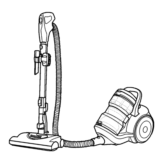
Vacuum Cleaner
MC-CL935-00
PAGE
Advertisement
Table of Contents

Related Manuals for Panasonic MC-CL935-00


Summary of Contents for Panasonic MC-CL935-00
-
Page 1: Table Of Contents
2.7. Power Nozzle Motor -------------------------------------- 7 4.5. Hose--------------------------------------------------------- 20 2.8. Hose Handle ------------------------------------------------ 8 4.6. Wand & Tools --------------------------------------------- 21 2.9. Hose Swivel------------------------------------------------10 4.7. Packing ----------------------------------------------------- 22 3 Wiring Diagrams -------------------------------------------------11 © Panasonic Corporation 2014 Unauthorized copy- ing and distribution is a violation of law. -
Page 2: Specifications
1 Specifications Model MC-CL935-00 Power Source AC 120V (60 Hz) Input Power 12.0 Amps Cord Length 7.3 m (24 ft.) Motor Protection Washable Primary Filter Exhaust Filter HEPA Media Dimensions (W x H x L) 36.5 x 38 x 108 cm Weight 7.5 kg (16.5 lbs) -
Page 3: Disassembly And Assembly Instructions
2 Disassembly and Assembly Instructions 4. Press the sides of the handle inward and lift off. 2.1. Cord Reel 2.1.1. Removal 1. Lift the dust cup handle and remove dust cup from canister. 2. Remove two (2) screws from canister carry handle. 5. - Page 4 14. Disconnect cord reel lead wire from overload protector and cut white lead wire lead wire just below crimp connector. 2.1.2. Reinstallation 8. Remove seven (7) screws as shown. 1. Strip white lead wire from motor which was cut during removal of cord reel approximately 1/4”...
-
Page 5: Fan Motor
2.2. Fan Motor 2.3. Triac PCB 2.2.1. Removal 2.3.1. Removal 1. Remove dust cup, handle cover, handle, cover, upper 1. Remove dust cup, handle cover, handle, cover, upper body. (see CORD REEL) body (see CORD REEL), Remove motor assembly (see 2. Remove connector pipe. CANISTER MOTOR). -
Page 6: Power Nozzle Cover
2. Rotate cover back. Press cover firmly until side and rear 2.4. Power Nozzle Cover tabs snap into place. Turn Power Nozzle upside down and replace two (2) cover screws. 2.4.1. Removal 1. Turn Power Nozzle upside down. 2. Unscrew the two (2) Power Nozzle cover screws. 2.5. -
Page 7: Power Nozzle Light Bulb
5. Insert a flat screwdriver blade between the indicator block 2.6. Power Nozzle Light Bulb assembly and the plastic retainer for the four (4) wires. Pry up and out to free the indicator block assembly from 2.6.1. Bulb Removal the retaining tabs. 1. -
Page 8: Hose Handle
4. Install indicator block assembly. Holding the assembly at 3. Remove sliding knob. a slight angle, insert the edge of the part behind the retaining tabs (use T-shaped tab on assembly to align in slot of retaining tab). With fingers lifting base off the floor (to free front axle) use both thumbs to push the indicator block assembly down until it snaps in place. - Page 9 2. Push hose in place on curved pipe unit, and press each of 6. Install right handle half and secure with two (2) screws. the hose wires into retainer slots. 3. Plug curved pipe unit and P.C.B. assembly wires to the same color hose wires (blue wire to blue wire, white to 7.
-
Page 10: Hose Swivel
2.9. Hose Swivel 2.9.1. Removal 1. Wrap a cloth around hose adapter to protect from scuff- ing/scratching. 2. Place the swivel in a vise. 3. Top of the hose adapter should extend 3/8-inch to 1/2- inch above the top of the vise jaws. 4. -
Page 11: Wiring Diagrams
3 Wiring Diagrams 3.1. Schematic... -
Page 12: Wire Management - Canister
3.2. Wire Management - Canister NOTE: For general servicing, it is necessary to eliminate pinching of any wire during reassembly. After servicing any electrical com- ponent or electrical enclosure, the unit should be reassembled and checked for dielectric breakdown or current leakage. -
Page 13: Wire Management - Power Nozzle
3.3. Wire Management - Power Nozzle NOTE: For general servicing, it is necessary to eliminate pinching of any wire during reassembly. After servicing any electrical com- ponent or electrical enclosure, the unit should be reassembled and checked for dielectric breakdown or current leakage. -
Page 14: Exploded View And Replacement Parts List
4 Exploded View and Replacement Parts List 4.1. Canister 4.1.1. Exploded View... -
Page 15: Parts List
4.1.2. Parts List Safety Ref. No. Part No. Part Name & Description Qty. Remarks AC03ADXEZV07 Lower Body AC93CAKTZV07 Caster Roller Unit AC99NDXEZV07 Cord Reel Assembly AC99CDXEZU03 Wheel Unit (Rear) AC17HDXFZV07 Air Inlet Plate AXTN4+20BFY Screw 10 PER PACKAGE AC95CAKTZV06 Caster Wheel AC76FDXFZ000 Overload Protector AC4154460... -
Page 16: Fan Motor
4.2. Fan Motor 4.2.1. Exploded View 4.2.2. Parts List Safety Ref. No. Part No. Part Name & Description Qty. Remarks AC09FDXEZ000 Motor Case AC03FAFVZ000 Motor Support Rubber AC44KDXEZ000 Filter AC92FDJHZ000 Fan Motor Unit AC02FDJHZ000 Motor Support Rubber AC63FDXEZV07 Motor Support Cover AC75ADXEZ000 Packing AC85WDYUZ000... -
Page 17: Dust Cup
4.3. Dust Cup 4.3.1. Exploded View 4.3.2. Parts List Safety Ref. No. Part No. Part Name & Description Qty. Remarks AC52FDXEZV07 Fan Blade AC74EDXEZU00 Seal A AC20HDXEZPUH Lid (Deco) AC64BDXEZP0H Handle (Cup) AC69KJMZV07 Protector AC70KDVJZP00 Protector Spring AC68KAJDZV07 Protector Cover AC44KDMTZ000 Filter AC75KDXEZP0H... -
Page 18: Power Nozzle
4.4. Power Nozzle 4.4.1. Exploded View... - Page 19 4.4.2. Parts List Safety Ref. No. Part No. Part Name & Description Qty. Remarks AC50XDXEZU03 Product Assembly (Power Nozzle) AC98RDXEZU03 Floor Nozzle Upper Deco AC21HDGEZ000 Window AC13DDVUZRUK Button - Belt Reset AC21HGJZ000 Lens Height Adjust AC37KAKSZ000 Filter-Intake/Exhaust AMC681-550 Screw AC25QCREZV07 Swivel Cap AC28GBKHZ000 Bulb Light...
-
Page 20: Hose
4.5. Hose 4.5.1. Exploded View 4.5.2. Parts List Safety Ref. No. Part No. Part Name & Description Qty. Remarks AC68GBZTZU03 Switch Case AC02UDXEZVU6 Actuator (3 Pos Slide) Deco AC09ESTZ000 Switch 3-Position AXTN4+12BFY Screw 10 PER BAG AC93BBZTZV06 Handle Assembly AC54PAPAZV06 Suction Control AC98PSTZV06 Curve Pipe Unit... -
Page 21: Wand & Tools
4.6. Wand & Tools 4.6.1. Exploded View 4.6.2. Parts List Safety Ref. No. Part No. Part Name & Description Qty. Remarks AC60RSJZV06 Crevice Tool AC80SCRZZV0N Turbine Unit AC88RAKZZV06 Dusting Brush AC99PDXEZV06 Extension Wand AC69PDXEZV06 Tool Caddy Assembly AC66PDXEZV06 Tool Caddy AC82DDXEZV06 Locking Clip... -
Page 22: Packing
4.7. Packing 4.7.1. Exploded View 4.7.2. Parts List Safety Ref. No. Part No. Part Name & Description Qty. Remarks AC61ZDXEZ0U0 Individual Carton AC01ZDXEZ000 Operating Instructions English/French/Spanish...