Sign In
Upload
Manuals
Brands
Sony Manuals
Projector
RM-PJM15
Sony RM-PJM15 Manuals
Manuals and User Guides for Sony RM-PJM15. We have
2
Sony RM-PJM15 manuals available for free PDF download: Service Manual
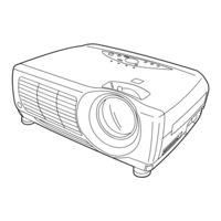
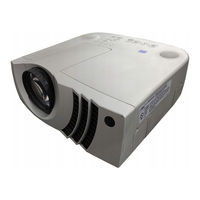
Sony RM-PJM15 Service Manual (196 pages)
LCD Data Projector, Projection Lens (Not Included), Remote Commander
Brand:
Sony
| Category:
Projector
| Size: 14.99 MB
Table of Contents
Service Manual
1
Table of Contents
5
2 Service Informations
65
Board Layout
65
Disassembly
66
Hood Assembly and Front Assembly Removal
66
H Board Removal
67
NF Board Removal
67
C Board Removal
68
BB and BA Boards Removal
69
Power Block Removal
70
Optics Unit Assembly Removal
71
GA Board Removal (VPL-PX15 Only)
72
CE Block Removal (VPL-PX15 Only)
73
QC and CM Boards Removal (VPL-PX15 Only)
74
Parts from the QC Board Removal (VPL-PX15 Only)
75
QA Board Removal
76
QB Board Removal
77
F and V Boards Removal
78
Prism Block Assembly and Polarizer Removal
79
Lamp Assembly Removal
80
Extension Boards and Extension Cables Connection
81
VPL-PX15 Tool for Writing Network Software
82
Power Cord
83
Main Soft and Pixel Works Soft Writing
84
3 Electrical Adjustments
85
Preparations
85
Equipment Required
85
How to Enter and Use the Factory Mode
85
V-COM Adjustment
85
Adjustment Item Initialize Data
86
Service Kowhow
94
After Replacing the Prism Block
94
After Replacing the Board
94
When Replacing the BA Board
94
When Replacing the C Board
94
When Replacing the Other Board
94
White Balance Adjustment
95
Signal Level Adjustment
95
HIGH Mode of INPUT-A
95
LOW Mode of INPUT-A
95
LOW Mode of VIDEO
95
Memory
96
4 Semiconductors
101
5 Spare Parts
105
Notes on Repair Parts
105
Exploded Views
106
Electrical Parts List
114
6 Block Diagrams
143
Overall
143
Ba, Bb (1/5), Qa (1/2)
144
Bb (2/5), (3/5), Nf, Qa (2/2), Qb
145
F, G, Ga
149
7 Diagrams
151
Frame Schematic Diagram
152
Frame (1/3)
152
Frame (2/3)
153
Frame (3/3)
154
Schematic Diagrams and Printed Wiring Boards
155
Advertisement
Sony RM-PJM15 Service Manual (150 pages)
Data projector
Brand:
Sony
| Category:
Projector
| Size: 15.28 MB
Table of Contents
Table of Contents
3
1 Service Informations
9
Circuit Boards Location
9
Servicing Tools
9
XA, XAA Extension Boards (70P)
9
XB, XBB Extension Boards (50P)
9
Cabinet Assy Removal
10
Front Block Assy Removal
10
NF Board Removal
11
BA and y Boards Removal
11
Power Block Removal
12
G Block Assy (GA, GB, GC and GD Boards) Removal
12
C Board Removal
13
Optics Unit Assy Removal
13
BC and KS Boards Removal
14
Connector Block Assy Removal
14
BB, QA, QB, QC and QD Boards Removal
15
F, K Boards and AC Inlet Removal
15
Lens Assy Removal
16
Prism Block and Polarizer Removal
16
Note on Lamp Breakage
17
2 Electrical Adjustments
19
Equipment Required
19
Preparations
19
Turning on the Power
19
Setting the Factory Mode
19
C Board Adjustments
19
R VCOM Adjustments
19
G VCOM Adjustments
19
B VCOM Adjustments
19
Signal Level Adjustments
19
VIDEO NTSC Level Adjustments
20
VIDEO PAL Level Adjustments
20
Y/PB/PR Level Adjustments
20
RGB Level Adjustments
21
W/B Adjustment
22
RGB W/B HIGH Adjustment
22
RGB W/B LOW Adjustment
22
Component W/B HIGH Adjustment
23
Component W/B LOW Adjustment
23
Adjustments in Replacement of Prism and Optical Unit
24
COM Adjustment
24
Polarization Plate Adjustment
24
GAMMA Adjustment (Outline)
24
GAMMA Adjustments
24
Adjustment Item Initialize Data
25
3 Theory of Operation
29
BA Board
29
Main IC Functions
29
Signal Path
29
Path of SYNC Processing
30
Clamp Pulse Generation Circuit
30
BB Board
31
BC Board
32
C Board
33
Timing Generator
33
LCD Driver Control Pulse
33
Y Board
34
Microprocessor Peripheral Circuit
34
USB Circuit
35
Terminal Functions of MAIN CPU
35
Description of QA Board Operations
38
Switching of Video Signals
38
Switching of Audio Signals
39
Monitoring of the USB Power Supply
39
Description of QB Board Circuit Operations
40
INPUT a Input
40
DDC Memory
40
INPUT a Mouse Driver
40
Description of QC Board Circuit Operations
41
INPUT B Inputs
41
DDC Memory
41
INPUT a Mouse Driver
41
Description of QD Board Circuit Operations
42
RS-232C Communication
42
Reception of Remote Control Signals
42
Video Input
42
Description of K Board Circuit Operations
42
Description of KS Board Circuit Operations
42
Voltage Map of F, GA, GB, GC and GD Boards
43
Voltages Map of F, GA, GB, GC and GD Boards
43
F Board
43
GA Board
44
Main Converter
44
Basic Operations of Sub-Converter
48
Details of Parts
49
GC, and GD Boards
50
4 Semiconductors
57
5 Spare Parts
57
Notes on Repair Parts
57
Exploded Views
58
Electrical Parts List for Boards
63
Parts List for Frame
91
Packing Materials
91
6 Block Diagrams
93
Overall
93
Advertisement
Related Products
Sony RM-PJM10
Sony RM-PJM11
Sony RM-PJM600
Sony RM-PJM12
Sony RM-PJM17
Sony RM-PJM610
Sony RM-PJM16
Sony RM-PJM50
Sony RM-PJM1
Sony RM-PJHS1
Sony Categories
Laptop
TV
Camcorder
CD Player
Digital Camera
More Sony Manuals
Login
Sign In
OR
Sign in with Facebook
Sign in with Google
Upload manual
Upload from disk
Upload from URL