Sign In
Upload
Manuals
Brands
Siemens Manuals
Controller
LMV27.100x2
Siemens LMV27.100x2 Manuals
Manuals and User Guides for Siemens LMV27.100x2. We have
1
Siemens LMV27.100x2 manual available for free PDF download: Basic Documentation
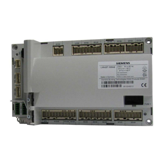
Siemens LMV27.100x2 Basic Documentation (219 pages)
Basic unit with integrated air-fuel ratio control for forced draft burners
Brand:
Siemens
| Category:
Controller
| Size: 4.33 MB
Table of Contents
Table of Contents
3
1 Safety Notes
9
Warning Notes
9
Mounting Notes
10
Installation Notes
11
Electrical Connection of the LMV27
12
Connection BCI Via Integrated RJ11 Jack (X56)
13
Electrical Connection of Flame Detectors
14
Commissioning Notes
15
Notes on Settings and Parameter Settings
17
Standards and Certificates
18
Service Notes
19
Life Cycle
19
Disposal Notes
19
2 System Structure / Function Description
20
For Europe
20
General Information
21
3 Type Summary
21
4 Technical Data
22
LMV27 Basic Unit
22
Terminal Loading Inputs
22
Terminal Loading Outputs
23
Analog Output / Load Output X74 Pin 3
23
Cable Lengths
24
Cross-Sectional Areas
24
Connections of Actuators
24
AGV50 Signal Cable from AZL2 BCI
25
Environmental Conditions
25
Flame Detectors
26
Ionization Probe
26
UV Flame Detectors QRA2 / QRA4 / QRA10
28
Photoresistive Flame Detectors QRB1 / QRB3
29
Yellow Flame Detector QRB4
30
Blue-Flame Detectors QRC
31
5 Dimensions
32
Lmv27
32
6 Display and Diagnostics
33
7 Basic Unit LMV27
33
Description of Inputs and Outputs
33
Flame Detectors
34
Loss of Flame
34
Extraneous Light
35
No Flame at the End of Safety Time (TSA)
35
Flame Intensity
35
Supervision of Flame Detector
35
Digital Input
36
Safety Loop X3-04, Pin 1 and 2
36
Burner Flange X3-03, Pin 1 and 2
37
Input for External Load Controller (on / OFF) X5-03, Pin 1
37
Inputs X5-03 Pin 2 and 3 (Opening / Closing or Stage 2 / Stage 3)
37
Air Pressure Switch X3-02
38
Gas Pressure Switch for Valve Proving X9-04
39
Gas / Oil Pressure Switch-Min, Start Release Gas X5-01
40
Setting the Time for Making the Pressure Switch Test
42
Gas / Oil Pressure Switch-Max / Oil Pressure-Max or POC Contact, Start Release Oil X5-02
43
Reset X8-04, Pin 1
44
Digital Outputs
45
Output Alarm Type No-SI - X3-05, Pin 2
45
Fan Motor Contactor Type si - X3-05, Pin 1
45
Continuous Fan Operation - X3-05, Pin 3
45
Output Ignition Type si (IGNITION) - X4-02
46
Outputs Fuel Valves V1 / V2 / V3 / PV, Type si - X8-02, X7-01, X7-02
47
Output Safety Valve Type si - X6-03
47
Output for Indication of Operation X8-04, Pin 2
47
Program Sequence
48
Time Parameters
48
Valve Proving
49
Valve Proving with Separate Pressure Switch X9-04
50
Valve Proving Via Gas Pressure Switch-Min X5-01
51
Lockout Phase (Phase 00)
51
Safety Phase (Phase 01)
52
Special Functions During the Program Sequence
53
Reset / Manual Lockout
53
Alarm Upon Start Prevention
54
Possible Start Preventions
54
Repetition Counter
55
Start Without Prepurging (as Per en 676)
57
Gas Shortage Program
58
Program Stop Function
59
Forced Intermittent Operation (<24 Hours)
59
Low-Fire Shutdown
59
Continuous Fan
60
Test Function for Approval of Burner - Loss-Of-Flame Test (TÜV Test)
61
Postpurging in the Lockout Position
62
Fuel Trains (Application Examples)
63
Sequence Diagrams
71
Gas Direct Ignition "G", "G Mod", "G Mod Pneu
71
Gas Pilot Ignition 1 "Gp1", "Gp1 Mod", "Gp1 Mod Pneu
72
Gas Pilot Ignition 2 "Gp2", "Gp2 Mod", "Gp2 Mod Pneu
73
Light Oil Direct Ignition "Lo", "Lo Mod", "Lo 2 Stage", " lo 3-Stage
74
Light Oil - Pilot Ignition "Logp""Logp Mod" "Logp 2-Stage
75
Legend to the Sequence Diagrams
76
8 Selection of Operating Mode
79
Deleting Curves
81
9 Connection to Load Controllers
82
Load Controller on Contact X5-03, Pin 1
82
External Load Controller Via Contacts X5-03, Pin 2 / Pin 3
82
Default Output Via Building Automation - X92
85
Manual Output
86
Output with Curve Settings
86
Prioritization of Load Controller Sources
87
Emergency Operation with Several Load Controller Sources
87
Manual Control
87
10 Electronic Air-Fuel Ratio Control
89
General
89
Behavior Outside the Operating Positions
89
Traveling Speed
89
Home Position
89
Prepurging
89
Ignition
90
Postpurging
90
Modulating Operation
91
Definition of Curves
91
Traveling Speed/Maximum Curve Slope
92
Entering the Running Position
92
Operating Position
92
Limitation of Modulation Range
93
Setting the Minimum and Maximum Output
94
Multistage Operation
95
Definition of Curves
95
Traveling Speed
95
Adjustment of Output
96
Entering the Operating Position
96
Operating Position
96
Limitation of Modulation Range
97
End of Operating Position
97
Notes on Settings and Parameter Settings
97
11 Actuators X53 / X54
98
Function Principle
98
Definition of Angles
98
Referencing
99
Reference Travel
101
Direction of Rotation
103
Monitoring the Actuator Positions
104
Changing the Error Detection Band for Monitoring the Actuator Positions
105
Forced Travel
105
Detection of Line Interruptions
105
Protection against Actuator Mixup
106
Proposal for Implementation
106
12 Load Output X74 Pin 3
107
Safe Separation of Mains Voltage and Extra Low-Voltage
107
Modulating Operation
108
2-Stage Operation
108
13 Fuel Meter Input X75 Pin 1 / X75 Pin 2
109
Configuration of Fuel Meter
109
Types of Fuel Meters
109
Configuration of Pulses Per Volume Unit
109
Reading and Resetting the Meter Readings
109
Fuel Throughput
110
Configuration
110
Reading out the Fuel Throughput
110
14 Connection and Internal Diagram
111
15 Special Feature: Burner Identification
112
16 Connection to Superposed Systems
112
General Information and Building Automation Functions
112
Modbus
113
17 PC Software ACS410
114
18 Error History
115
Error Classes
115
Makeup of Error History
116
19 Lifecycle Function
117
20 Safety Notes on Use of the AZL2
117
21 Operating Via AZL2 Unit
118
Description of Unit / Display and Buttons
118
Meaning of Symbols on the Display
119
Brightness of Display
119
Special Functions
120
Manual Lockout
120
Manual Control (Manual Request for Output)
121
Timeout for Menu Operation
122
Backup / Restore
122
Backup
123
Restore
125
22 Operation of LMV27 Via the AZL2
127
Normal Display
127
Display in Standby Mode
127
Display During Startup / Shutdown
127
Display of Program Phases
127
Display of Program Phase with Remaining Running Time until End of the Phase Is Reached
127
List of Phase Displays
128
Display of Operating Position
129
Fault Status Message, Display of Errors and Info
130
Display of Errors (Faults) with Lockout
130
Reset
130
Activating Info / Service Mode from Lockout
130
Error with Safety Shutdown
131
General Information
131
Start Prevention
131
Safety Loop
131
23 Menu-Driven Operation
132
Assignment of Levels
132
24 Info Level
133
Display of Info Level
133
Display of Info Values (Examples)
134
Identification Date
134
Identification Number
134
Burner Identification
135
Number of Startups Resettable
136
Total Number of Startups
137
End of Info Level
137
25 Service Level
138
Display of Service Level
138
Display of Service Values (Example)
139
Number of Faults
139
Error History
139
Intensity of Flame
139
End of Service Level
139
26 Parameter Level
140
Entry of Password
141
Entry of Burner Identification
143
Change of Heating Engineer's Password
145
Change of Oem's Password
146
Use of Parameter Level
147
Structure of Parameter Levels
148
Parameters Without Index, with Direct Display
149
Using the Example of Parameter 208: Program Stop
149
Parameters Without Index, with no Direct Display (with Parameters Having a Value Range > 5 Digits)
151
Using the Example of Parameter 162: Operating Hours Resettable
151
Parameter with Index, with Direct Display
153
Using the Example of Parameter 501: No-Flame Positions Fuel Actuator
153
Parameters with Index, with no Direct Display
155
Using the Example of Parameter 701: Errors
155
Fuel / Air Ratio Curves - Settings and Commissioning
158
Initial Commissioning
158
Setting Curvepoints P0 and P9 for Modulating Mode
161
Mod", "Gp2 Mod" and "Lo Mod")
161
Setting Curvepoints P0 and P9 for "G Mod Pneu", "Gp1 Mod Pneu" and "Gp2 Mod Pneu
162
Warm Settings for Modulating Mode
163
Mod" and "Lo Mod")
163
Warm Settings for Modulating Mode ("G Mod Pneu", "Gp1 Mod Pneu" and "Gp2 Mod Pneu")
168
Cold Settings for "G Mod", "Gp1 Mod", "Gp2 Mod" and "Lo Mod
168
Cold Settings for "G Mod Pneu", "Gp1 Mod Pneu" and "Gp2 Mod Pneu
169
Editing the Curvepoints
170
Interpolation of Curvepoints
171
Setting of Curvepoints for Multistage Mode ("Lo 2 Stage" and "Lo 3 Stage")
174
Warm Settings for "Lo 2 Stage" and " lo 3 Stage
175
Cold Settings for Multistage Mode ("Lo 2 Stage" and " lo 3 Stage")
179
Intensity of Flame During Curve Settings
180
27 Parameter List
181
28 Error Code List (of All LMV2 / LMV3 Types)
193
29 Revision History LMV27
210
30 List of Figures
217
Advertisement
Advertisement
Related Products
Siemens LMV37.4 Series
Siemens LMV36.520 Series
Siemens LMV60.110A2
Siemens LME SERIES
Siemens LME41.051A2
Siemens LME71
Siemens LMG25.350A27
Siemens LME73.000A1
Siemens LME44.056A2
Siemens LME41.054A2
Siemens Categories
Industrial Equipment
Controller
Control Unit
Oven
Washer
More Siemens Manuals
Login
Sign In
OR
Sign in with Facebook
Sign in with Google
Upload manual
Upload from disk
Upload from URL