Sign In
Upload
Manuals
Brands
Samsung Manuals
Heat Pump
DVM S AM200FXVAGR
Samsung DVM S AM200FXVAGR Manuals
Manuals and User Guides for Samsung DVM S AM200FXVAGR. We have
4
Samsung DVM S AM200FXVAGR manuals available for free PDF download: Service Manual, Installation Manual
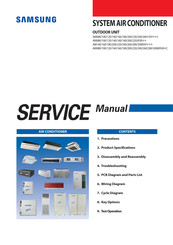
Samsung DVM S AM200FXVAGR Service Manual (273 pages)
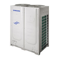
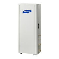
OUTDOOR UNIT
Brand:
Samsung
| Category:
Air Conditioner
| Size: 18.68 MB
Table of Contents
Table of Contents
2
1 Precautions
5
Precautions for the Service
5
Precautions for the Static Electricity and PL
5
Precautions for the Safety
5
Precautions for Handling Refrigerant for Air Conditioner
6
Precautions for Welding the Air Conditioner Pipe
6
Precautions for Additional Supplement of Air Conditioner Refrigerant
6
Other Precautions
6
2 Product Specifications
7
The Feature of Product
7
Feature
7
Changes in Comparison to Basic Mode
9
Structure of Product(Heat Pump)
15
Structure of Product(Heat Recovery)
16
Structure of Product(Power Supply for 460V, 60Hz, 3Φ)
17
Structure of Product (DVM S WATER)
18
Structure of Product (Heat Pump am KX Series)
20
Product Specifications
21
Outdoor Unit
21
Accessory and Option Specifications
39
Accessories
39
3 Disassembly and Reassembly
40
Necessary Tools
40
Disassembly and Reassembly
41
Am080/100/120Jxv
41
Am140Fxvagh, Am140Jxv Gh
51
Am160/180/200/220/240/260
61
Am140Jxva H
61
Am080/100/120Fxwa
72
Am200Fxwa
80
Am140/160Kxvg , Am140/160/180Kxva
87
Am180/200/220Kxvg , Am200/220Kxva
94
Am240/260/280/300Kxv , Am080Kxvs
102
Caution at Compressor Exchange
111
Mcu
116
Eev Kit
117
4 Troubleshooting
118
Check-Up Window Description
118
Service Operation
119
Special Operation
119
DVM S Models EEPROM Code Table
129
Number Display Method
130
Appropriate Measures for Different Symptom
135
Outdoor Unit Operation Flow
135
Main PCB Has no Power Phenomenon
138
Communication Error between Indoor and Outdoor Units During Tracking
139
Communication Error between Indoor and Outdoor Units after Tracking
141
Communication Error between Main and Sub Unit of Outdoor Unit or between Outdoor Units
142
Internal Communication Error of the Outdoor Unit C-Box
143
Internal PCB Communication Error of the Outdoor Unit C-Box
144
MCU Branch Part Setup Error-Inconsecutive Connection with the Use of 2 Branch Parts
146
MCU Branch Part Setup Error-Repeated Setup for the same Address over 3 Times
147
MCU Branch Part Setup Error-Non-Installed Address Setup
148
Setup Error for MCU Branch Part-Setup Error for MCU Quantity Used
149
MCU Branch Part Setup Error-Overlapping Indoor Unit Address Setup
150
MCU Branch Part Setup Error_Set as Being Used Without Connection to an Indoor Unit
151
MCU Branch Part Setup Error-Connect an Indoor Unit to a Branch Part Not Being Used
152
MCU Branch Part Setup Error-Connect more Indoor Units than What Is Actually Set up in MCU
153
MCU/MCU Subcooler Entrance/Exit Sensor Error (Open/Short)
154
Outdoor Temperature Sensor Error
155
Cond out Temperature Sensor Error (Open/Short)
156
Outdoor Cond out Sensor Breakway Error
157
Compressor Discharge or TOP 1/2 Temperature Sensor Error
159
Compressor Discharge or TOP Temperature Sensor Breakway Error
160
E269 : Suction Temperature Sensor Breakway Error
161
High Pressure Sensor Error (Open/Short)
162
Low Pressure Sensor Error (Open/Short)
163
Suction Temperature Sensor Error (Open/Short)
164
Liquid Pipe Temperature Sensor Error (Open/Short)
165
EVI in Temperature Sensor Error (Open/Short)
166
EVI out Temperature Sensor Error (Open/Short)
167
Suction-2 Temperature Sensor Error (Open/Short)
168
Measures of Other Outdoor Unit Error
169
E407 : Comp. down Due to High Pressure Protection Control
170
E410 : Comp. down Due to Low Pressure Protection Control
172
E416 : Suspension of Starting Due to Compressure Discharge Temperature Sensor/Top Temperature Sensor
174
3-Phase Input Wiring Error
175
E428 : Suspension of Starting by Abnormal Compression Ratio
176
EVI EEV Open Error
177
Refrigerant Leakage Error
178
Prevention of Heating/Cooling Operation Due to Outdoor Temperature
179
Prevention of Heating Refrigerant Charge Due to Outdoor Temperature
180
CH Wire Breaking Error
181
Fan Starting Error
183
Fan Lock Error
185
Momentary Blackout Error
186
Outdoor Fan Motor Overheating
187
Fan IPM Overheat Error
188
Compressor Starting Error
189
COMP Overcurrent Error
191
Overvoltage/Low Voltage Error
195
DC Link Voltage Sensor Error
196
Fan Motor Overcurrent Error
197
5 PCB Diagram and Parts List
199
Ass'y Pcb Main
199
Ass'y Pcb Main-Hub
202
Assy Pcb Inverter
206
Ass'y Pcb Fan
210
Ass'y Pcb Emi
214
Sub-Comm
217
6 Wiring Diagram
218
Am080/100/120/140/160/180/200/220Fxv
218
Am080/100/120/200Fxwa
219
Am080Jxvafh
221
Am100/120Jxvafh
222
Am140/160/180/200Jxvafh
223
Am080/100/120/140/160/180/200/220Jxvajh
224
7 Cycle Diagram
225
Am080/100/120 Xvh
225
Am140 XV Gh
225
Am160/180/200/220 Xvh
226
Am080/100/120 XV Gr
226
Am140 XV Gr
227
Am160/180/200/220 XV Gr
227
Am080/100/120Fxwa
228
Am200Fxwa
228
Am240/260Hxvagh/Eu
229
Am240/260/280Kxvg , Am280/300Kxva , Am080Kxvs
229
Am180/200/220Kxvg , Am200/220Kxva
230
Am140/160Kxvg , Am140/160/180Kxva
230
Cooling Operation (H/R)
231
Main Cooling Operation (H/R)
232
Heating Operation (H/R)
233
Main Heating Operation (H/R)
234
Cooling Operation (H/P)
235
Heating Operation (H/P)
236
Cooling Operation(H/R) - AM080/100/120/200FXWA
237
Main Cooling Operation(H/R)
238
Heating Operation(H/R)
239
Main Heating Operation(H/R)
240
Cycle Component Function Explanation
241
8 Key Options
242
Outdoor Unit Option Switch Settings
242
How to Set the Key Function of the Outdoor Unit
248
How to Check the View Mode Using a Tact Switch
256
9 Test Operation
258
Auto Trial Operation
258
Auto Trial Operation Synopsis
258
Auto Trial Operation Functions
260
How to Troubleshoot of the "Undetermined
261
Amount of Refrigerant Automatically Checking
271
Model Naming
272
Advertisement
Samsung DVM S AM200FXVAGR Service Manual (277 pages)
Brand:
Samsung
| Category:
Air Conditioner
| Size: 11.87 MB
Table of Contents
Table of Contents
2
Precautions
6
Precautions for the Service
6
Precautions for the Static Electricity and PL
6
Precautions for the Safety
6
Precautions for Handling Refrigerant for Air Conditioner
7
Precautions for Welding the Air Conditioner Pipe
7
Precautions for Additional Supplement of Air Conditioner Refrigerant
7
Other Precautions
7
Product Specifications
8
The Feature of Product
8
Feature
8
Changes in Comparison to Basic Mode
10
Structure of Product ( Heat Pump: AMSSSSXVSSH Series )
14
Structure of Product (Heat Recovery: AMSSSSXVSSR Series )
15
Structure of Product (Power Supply for 460V, 60Hz, 3Φ : AMSSSSXVSSJS Series )
16
Structure of Product (Heat Pump AMSSSKXS Series)
18
Structure of Product (Cooling Only AMSSSMXVAFC Series)
19
Structure of Product (Cooling Only AMSSSMXVAGC Series)
21
Product Specifications
22
Outdoor Unit
22
Accessory and Option Specifications
52
Accessories
52
Disassembly and Reassembly
53
Necessary Tools
53
Disassembly and Reassembly
54
Am080/100/120Jxvsss
59
Am140Fxvagh, Am140Jxvsgh
65
Am140/160/180/200Mxvafc
75
Am240/260/280/300Kxvsss, Am080Kxvsss, Am240/260/280/300Mxvagc
104
Caution at Compressor Exchange
114
Mcu
119
Eev Kit
120
Troubleshooting
121
Check-Up Window Description
121
Service Operation
122
Special Operation
122
DVM S Models EEPROM Code Table
129
Appropriate Measures for Different Symptom
134
Outdoor Unit Operation Flow
134
Main PCB Has no Power Phenomenon
137
Communication Error between Indoor and Outdoor Units During Tracking
138
Communication Error between Indoor and Outdoor Units after Tracking
140
Communication Error between Main and Sub Unit of Outdoor Unit or between Outdoor Units
141
Internal Communication Error of the Outdoor Unit C-Box
142
Internal PCB Communication Error of the Outdoor Unit C-Box
143
MCU Branch Part Setup Error-Inconsecutive Connection with the Use of 2 Branch Parts
145
MCU Branch Part Setup Error-Repeated Setup for the same Address over 3 Times
146
MCU Branch Part Setup Error-Non-Installed Address Setup
147
Setup Error for MCU Branch Part-Setup Error for MCU Quantity Used
148
MCU Branch Part Setup Error-Overlapping Indoor Unit Address Setup
149
MCU Branch Part Setup Error_Set as Being Used Without Connection to an Indoor Unit
150
MCU Branch Part Setup Error-Connect an Indoor Unit to a Branch Part Not Being Used
151
MCU Branch Part Setup Error-Connect more Indoor Units than What Is Actually Set up in MCU
152
MCU/MCU Subcooler Entrance/Exit Sensor Error (Open/Short)
153
Outdoor Temperature Sensor Error
154
Cond out Temperature Sensor Error (Open/Short)
155
Outdoor Cond out Sensor Breakway Error
156
Compressor Discharge or TOP 1/2 Temperature Sensor Error
158
Compressor Discharge or TOP Temperature Sensor Breakway Error
159
E269 : Suction Temperature Sensor Breakway Error
160
High Pressure Sensor Error (Open/Short)
161
Low Pressure Sensor Error (Open/Short)
162
Suction Temperature Sensor Error (Open/Short)
163
Liquid Pipe Temperature Sensor Error (Open/Short)
164
EVI in Temperature Sensor Error (Open/Short)
165
EVI out Temperature Sensor Error (Open/Short)
166
Suction-2 Temperature Sensor Error (Open/Short)
167
Measures of Other Outdoor Unit Error
168
E407 : Comp. down Due to High Pressure Protection Control
169
E410 : Comp. down Due to Low Pressure Protection Control
171
E416 : Suspension of Starting Due to Compressure Discharge Temperature Sensor/Top Temperature Sensor
173
3-Phase Input Wiring Error
174
E428 : Suspension of Starting by Abnormal Compression Ratio
175
EVI EEV Open Error
176
Refrigerant Leakage Error
177
Prevention of Heating/Cooling Operation Due to Outdoor Temperature
178
Prevention of Heating Refrigerant Charge Due to Outdoor Temperature
179
Wire Breaking Error
180
Fan Starting Error
182
Fan Lock Error
184
Momentary Blackout Error
185
Outdoor Fan Motor Overheating
186
Fan IPM Overheat Error
187
Compressor Starting Error
189
COMP Overcurrent Error
190
Overvoltage/Low Voltage Error
194
DC Link Voltage Sensor Error
195
Fan Motor Overcurrent Error
196
Input/Output Current Sensor Error
198
Outdoor Fan PCB Overvoltage/Low Voltage Error
199
Hall IC(Fan) Error
200
Inverter Overheat Error
201
Option Setting Error of Outdoor Unit
202
Error Due to Using Single Type Outdoor Unit in a Module Installation
203
Indoor Unit and MCU Address Duplication Error
204
PCB Diagram and Parts List
205
Ass'y Pcb Main
205
Ass'y Pcb Main-Hub
209
Assy Pcb Inverter
212
Ass'y Pcb Fan
216
Ass'y Pcb Emi
220
Sub-Comm
223
Wiring Diagram
224
Am080/100/120/140/160/180/200/220Fxvsss
224
Am080Jxvafh
226
Am100/120Jxvafh
227
Am140/160/180/200Jxvafh
228
Am080/100/120/140/160/180/200/220Jxvajh
229
Am100/120/180/200Mxvafc, Am160/180/260/280/300Mxvagc
230
Cycle Diagram
232
Am240/260Hxvagh/Eu
236
Am080/100/120Mxva*C
238
Am140/160/180Mxvagc
239
M200/220Mxvagc
240
Am240/260/280/300Mxvagc
241
Am140/160/180/200Mxvafc
242
Cooling Operation (H/R)
243
Main Cooling Operation (H/R)
244
Heating Operation (H/R)
245
Main Heating Operation (H/R)
246
Cooling Operation (H/P)
247
Heating Operation (H/P)
248
Cycle Component Function Explanation
249
Key Options
250
Outdoor Unit Option Switch Settings
250
How to Set the Key Function of the Outdoor Unit
254
How to Check the View Mode Using a Tact Switch
259
Samsung DVM S AM200FXVAGR Installation Manual (113 pages)
Brand:
Samsung
| Category:
Air Conditioner
| Size: 9.45 MB
Table of Contents
Table of Contents
2
Severe Warning Signs
3
Safety Precautions
3
Checks before Installation and Service Work
4
Caution Signs
5
Do Not Install the Product in Following Places
5
Outdoor Unit Classification
6
Packaging Material Disposition
6
Preparing for Installation
6
Outdoor Unit Combination
7
Standard Type (Heat Pump)
7
Preparing for Installation - Tables
8
When Moving with a Forklift
17
When Moving Product Without Wooden Pallet and Crane Is Not Available
17
Moving the Outdoor Unit
17
When Moving with a Crane
17
Caution When Installing the Product in Seashore
18
Selecting Installation Location
18
Single Installation
21
Space Requirement for Installation
21
Module Installation
22
Accessories
23
Base Ground Construction
24
Base Construction and Installation of the Outdoor Unit
24
Outdoor Unit Installation
25
Outdoor Unit Base Mount and Anchor Bolt Position
25
Examples of Draining Work
26
Cautions Regarding on Connecting the Anchor Bolt
27
Cautions Regarding on Connecting the Pipe
27
Cautions Regarding on Anti-Vibration Frame Installation
27
Caution for Installing Discharge Duct
28
Installing the Outdoor Unit Around the Obstacles
28
Installing the Wind/Snow Prevention Duct
28
Cautions Regarding Installing the Frame and Selecting the Base Ground
29
Installing the Outdoor Unit in Cold Region
29
Installing the Outdoor Unit in Windy Region
30
Refrigerant Pipe Installation
31
Selecting Refrigerant Pipe
32
Size of the Pipe Connected to the Outdoor Unit
33
Size of the Pipe between Branch Joints
34
Size of the Pipe between the Branch Joint and the Indoor Unit
34
Branch Joint
35
Y-Joint
35
Distribution Header
35
H/R
36
Branch Joint between Outdoor Units
38
First Branch Joint
38
Amount of Additional Refrigerant Depending on the Pipe Size
39
Additional Refrigerant
39
Basic Amount of Refrigerant Within the Outdoor Unit
39
Amount of Additional Refrigerant for each Indoor Unit
40
Method to Calculate Total Amount of Additional Refrigerant
41
Example of Refrigerant Calculation for HP Models
42
Temper Grade and Minimum Thickness of the Refrigerant Pipe
43
Keeping Refrigerant Pipe
44
Refrigerant Pipe Welding and Safety Information
44
Nitrogen Flushing Welding
44
Direction of the Pipe When Welding
44
Cutting or Flaring the Pipes
45
Connecting the Flared Pipes
46
Pipe Installation for an Outdoor Unit
47
Direction of the Pipe
47
Caution for Using Knock-Out Hole
47
Connecting Refrigerant Pipe for Outdoor Unit
48
Caution for Welding the Pipe to an Outdoor Unit
48
Pipe Installation between the Outdoor Units
49
Examples of Refrigerant Pipe Installation
50
Allowable Length of the Refrigerant Pipe and the Installation Examples
51
Installing the Branch Joints
56
Installing the Distribution Header
57
Installing the Branch Joint between Outdoor Units
58
Installation of Outdoor Joints
58
Install the Distribution Header Horizontally
58
Installing the MCU
60
MCU Specification
60
Installing the Indoor Units
61
How to Connect the Pipes
62
Specification of the Circuit Breaker and Power Cable
63
Electrical Wiring Work
63
Caution for Electrical Work
66
Power and Communication Cable Configuration
67
Specification of the Protection Tube
68
Caution for Perforating the Knock-Out Hole
68
Power Wiring Diagram
69
Selecting Solderless Ring Terminal
71
Connecting the Power Terminal
72
Examples of How to Use the Cable Striper
73
Fixing the Power Cable
74
Connect the Ring Terminal of 3 Phase Cable
74
Fixing the Ground Cable
75
Withdrawing the Power Cable
75
Installing the Solution Device
76
Connecting the MCU
77
Grounding Work
79
Grounding the Power Cable
79
Air Tightness Test and Vacuum Drying
80
Vacuum Drying Pipes and Indoor Units
81
Insulating the Refrigerant Pipes and Branch Joints
82
Selecting the Refrigerant Pipe Insulator
82
Pipe Insulation
82
Insulate the Refrigerant Pipe
83
Insulate the Distribution Header
84
Insulating the Branch Joint
84
Insulating the Pipe Located Inside of the Outdoor Unit
85
Charging Refrigerant (for the Turkish Market Only)
85
Using Service Valve for Gas
87
Basic Segment Display
88
Setting Outdoor Unit Option Switch and Key Function
88
Setting Outdoor Unit Option Switches: B Type
89
Setting Outdoor Install Option
89
Installing and Setting the Option with Tact Switch
90
Setting Key Operation and Checking the View Mode with Tact Switch
94
Setting the MCU Address and the MCU Ports to Use
98
Setting the MCU and Pipe Addresses (for HR Only)
98
Setting the Pipe Addresses Manually
99
Setting the Pipe Addresses Automatically (Auto Pipe Pairing Operation)
100
Check Items before Running the Auto Pipe Pairing Operation
100
To Run the Auto Pipe Pairing Operation
101
Things to Check after Completing the Installation
102
Checklist before Auto Trial Operation
104
Inspection and Test Operation
104
Auto Trial Operation
105
Inspection and Trial Operation
106
Measure to Take When E503 Error Occurs
106
Measure to Take When E505, E506 Error Occurs
108
Automatic Refrigerant Amount Detection Function
110
Advertisement
Samsung DVM S AM200FXVAGR Installation Manual (66 pages)
Brand:
Samsung
| Category:
Heat Pump
| Size: 2.85 MB
Table of Contents
Installation Manual
2
Table of Contents
3
Safety Precautions
3
Preparing the Installation
6
Selecting Installation Location
7
Hydro Unit
8
Base Construction and Installation of the DVM Hydro Unit / Hydro Unit HT
9
Refrigerant Pipe Installation
13
Performing Leak Test and Insulation
19
Installing the Drain Pipe
20
Water Pipe Installation
21
Connecting Power and Communication Cable
27
Connecting External Contact
37
Setting an Indoor Unit Address and Installation Option
51
Product Maintenance
59
Failure Diagnosis
60
Error Code
61
Using the PCB Switch
63
Completing the Installation
64
Explaining Functions to the User
64
Appendix
65
Advertisement
Related Products
Samsung DVM S AM200FXVAGH
Samsung AM200AXVDGH1EU
Samsung AM250FNBFEB/EU
Samsung AM250FNBFGB/EU
Samsung DVM S AM220FXVAGH
Samsung AM220AXVDGH1EU
Samsung AM240AXVDGH1EU
Samsung AM288BXVGFH/AA
Samsung AM216BXVTFH1AA
Samsung AM240BXVTFH1AA
Samsung Categories
Cell Phone
Monitor
Microwave Oven
LCD TV
Air Conditioner
More Samsung Manuals
Login
Sign In
OR
Sign in with Facebook
Sign in with Google
Upload manual
Upload from disk
Upload from URL