Sign In
Upload
Manuals
Brands
Motorola Manuals
Motherboard
MVME2100
Motorola MVME2100 Manuals
Manuals and User Guides for Motorola MVME2100. We have
2
Motorola MVME2100 manuals available for free PDF download: Installation And Use Manual, Programmer's Reference Manual
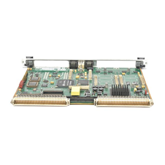
Motorola MVME2100 Installation And Use Manual (128 pages)
Brand:
Motorola
| Category:
Motherboard
| Size: 1.09 MB
Table of Contents
Table of Contents
7
Overview of Contents
16
Summary of Changes
16
Comments and Suggestions
17
Conventions Used in this Manual
18
Terminology
18
CHAPTER 1 Preparation and Installation
21
Introduction
21
Pmcspan Expansion Mezzanine
22
PCI Mezzanine Cards (Pmcs)
22
PC•MIP Expansion
22
Table 1-1. Pmcspan Models
22
VME System Enclosure
23
System Console Terminal
23
Unpacking the MVME2100 Hardware
24
Preparing the MVME2100 Hardware
24
MVME2100 Configuration Settings
24
Setting Flash Memory Bank A/Bank B Header (J9) (Pins 1 and 2)
25
Setting System Controller Selection Header (J2)
25
Pmcs
26
Pmcspan
26
System Console Terminal
26
Installing the MVME2100 Hardware
27
Figure 1-1. MVME2100 Layout
27
ESD Precautions
28
Pmcs & Pc•Mips
28
Figure 1-2. MVME2100 Installation and Removal from a Vmebus Chassis
29
Figure 1-3. Typical Single-Width PMC Module Placement on an MVME2100
30
Figure 1-4. Typical Type II PC•MIP Placement on an MVME2100
31
Primary Pmcspan
31
Figure 1-5. Pmcspan-001 Installation on an MVME2100
33
Secondary Pmcspan
34
Figure 1-6. Pmcspan-010 Installation on a Pmcspan-001/MVME2100
35
MVME2100 System Installation
37
Installation Considerations
39
CHAPTER 2 Operating Instructions
41
Introduction
41
Applying Power
41
Figure 2-1. System Boot-Up Sequence
42
MVME2100 User Interface Devices
43
Switches
43
Abt (S1)
43
Rst (S2)
44
Bfl (Ds1)
44
Sys (Ds2)
44
Run (Ds3)
44
10/100 BASE T Port
44
DEBUG Port
44
Jumper Settings
46
Table 2-1. Jumper Switches and Settings
46
I/O Expansion Cards
47
PCI Mezzanine Card
47
Type II Pc-Mip
47
CHAPTER 3 Functional Description
49
Introduction
49
Table 3-1. MVME2100 Features
49
Figure 3-1. MVME2100 Block Diagram
51
Functional Description
52
Processor
52
PCI Host Bridge/Memory Controller
52
PCI Bus Arbitration
52
PCI Local Bus
53
Interrupt Controller
53
Two-Wire Serial Interface
54
I2O Message Unit
54
Direct Memory Access (DMA)
54
Timers
54
System Clock Generator
55
Flash Memory
55
System Memory
55
Ethernet Interface
56
Asynchronous Serial Port
56
Figure 3-2. Asynchronous Serial Port Connections
56
Vmebus Interface
57
PCI Mezzanine Card Slot
57
PC•MIP Type I Mezzanine Card Slots
57
PC•MIP Type II Mezzanine Card Slots
57
PCI/PMC Expansion Capability
58
Real-Time Clock & NVRAM
58
CHAPTER 4 Ppcbug Firmware
59
Ppcbug Overview
59
Ppcbug Basics
59
Memory Requirements
61
Ppcbug Implementation
61
MPU, Hardware, and Firmware Initialization
61
Using Ppcbug
63
Debugger Commands
64
Table 4-1. Debugger Commands
65
Diagnostic Tests
69
Table 4-2. Diagnostic Test Groups
70
CHAPTER 5 Modifying the Environment
71
Overview
71
CNFG - Configure Board Information Block
72
ENV - Set Environment
73
Configuring the Ppcbug Parameters
73
Led/Serial Startup Diagnostic Codes
81
Configuring the Vmebus Interface
82
Firmware Command Buffer
86
APPENDIX A Related Documentation
87
Motorola Computer Group Documents
87
Table A-1. Motorola Computer Group Documents
87
Manufacturers' Documents
88
Table A-2. Manufacturers' Documents
88
Related Specifications
91
Table A-3. Related Specifications
91
APPENDIX B Specifications
93
Specifications
93
Mechanical Characteristics
93
Electrical Characteristics
93
Table B-1. Power Requirements for the MVME2100
93
Environmental Characteristics
94
Table B-2. MVME2100 Environmental Specifications
94
EMC Compliance
95
Thermal Validation
96
Thermally Significant Components
96
Table B-3. Thermally Significant Components
97
Figure B-1. Thermally Significant Components (Primary Side
98
Figure B-2. Thermally Significant Components (Secondary Side
99
Component Temperature Measurement
100
Preparation
100
Measuring Junction Temperature
100
Measuring Case Temperature
100
Figure B-3. Mounting a Thermocouple under a Heatsink
102
Measuring Local Air Temperature
103
Figure B-4. Measuring Local Air Temperature
103
APPENDIX C Connector Pin Assignments
105
Introduction
105
Vmebus Connectors
105
Table C-1. P2 Connector Pin Assignment
105
PC•MIP PCI Interface Connectors
107
Table C-2. PC•MIP P1/P2 Pin Assignments
107
PC•MIP User Defined I/O Connectors
109
Table C-3. PC•MIP Slot 2 User Defined I/O Connector P3
109
PCI Mezzanine Card (PMC) PCI Interface Connectors
110
Table C-4. PMC Connector J11/J12 Pin Assignments
110
PMC User Defined I/O Connector
112
Table C-5. PMC User Defined I/O Connector J14
112
PCI Expansion Connector
114
Table C-6. PCI Expansion Connector Pin Assignments
114
10Baset/100Basetx Connector
117
Asynchronous Serial Port Connector
117
Table C-7. 10Baset/100Basetx Connector Pin Assignments
117
Table C-8. Asynchronous Serial Connector Pin Assignments
117
Table C-9. Two-Wire Serial Interface Header Pin Assignments
118
Two-Wire Serial Interface Header
118
APPENDIX D Troubleshooting
119
Solving Startup Problems
119
Table D-1. Troubleshooting Problems
119
Advertisement
Motorola MVME2100 Programmer's Reference Manual (52 pages)
Brand:
Motorola
| Category:
Single board computers
| Size: 0.59 MB
Table of Contents
Table of Contents
7
Summary of Changes
13
Overview of Contents
13
Comments and Suggestions
14
Conventions Used in this Manual
14
Terminology
15
Introduction
17
What this Guide Provides
17
Table 1-1. MVME2100 Key Features
18
Memory Maps
20
Processor Memory Map
20
Address Map a (Prep)
20
Table 1-2. Processor Address Map a (Prep)
20
Address Map B (CHRP)
22
Table 1-3. Processor Address Map B (CHRP)
22
PCI Memory Map
23
PCI Memory Map a (Prep)
23
Table 1-4. PCI Memory Master View (Prep)
23
PCI Memory Map B (CHRP)
24
Table 1-5. PCI Memory Master View (CHRP)
24
PCI I/O Memory Map
25
PCI I/O Map a (Prep)
25
PCI I/O Map B (CHRP)
25
Table 1-6. PCI I/O Address Map a (Prep)
25
Table 1-7. PCI I/O Address Map B (CHRP)
25
System I/O Memory Map
26
Table 1-8. System I/O Memory Map
26
System Status Register 1
28
System Status Register 2
29
PCI Presence Detect Register
30
Table 1-11. PCI Presence Detect Register
30
Vmebus Geographical Address Register
31
Table 1-12. Vmebus Geographical Address Register
31
Configuration Header Register
32
Table 1-13. Configuration Header Register
32
SIMM/DIMM Parallel Presence Detection Registers
33
Table 1-14. SIMM/DIMM Parallel Presence Detection Registers
33
Introduction
35
PCI Arbitration
35
Interrupt Handling
36
Table 2-1. Serial Interrupt Assignments
36
EEPROM Functionality
37
SDRAM Configuration EEPROM
37
System Configuration EEPROM
37
Table 2-2. System EEPROM Device Ids
37
Input/Output Functionality
38
Ethernet Controller
38
PMC/PC-MIP Type I Expansion Slot
38
PC-MIP Type I Expansion Slot
38
PC-MIP Type II Expansion Slots
38
Vmebus Interface
38
PCI/PMC Expansion Capability
39
PCI Configuration Space
39
Table 2-3. IDSEL Mapping for PCI Devices
39
Memory Characteristics
40
System Memory
40
FLASH Memory
40
Table 2-4. FLASH Memory Configurations
40
Motorola Computer Group Documents
41
Table A-1. Motorola Computer Group Documents
41
Manufacturers' Documents
42
Table A-2. Manufacturers' Documents
42
Related Specifications
44
Table A-3. Related Specifications
44
MCG Customer Services
46
Advertisement
Related Products
Motorola MVME2603-1191A
Motorola MVME2305
Motorola MVME2700-1321
Motorola MVME2700-1431
Motorola MVME2700-1441
Motorola MVME2700-4221A
Motorola MVME2700-3421
Motorola MVME2700-3451
Motorola MVME2700-1341
Motorola MVME2604-2191A
Motorola Categories
Cell Phone
Two-Way Radio
Baby Monitor
Cordless Telephone
Radio
More Motorola Manuals
Login
Sign In
OR
Sign in with Facebook
Sign in with Google
Upload manual
Upload from disk
Upload from URL