Mitsubishi Electric MR-J3-B Manuals
Manuals and User Guides for Mitsubishi Electric MR-J3-B. We have 3 Mitsubishi Electric MR-J3-B manuals available for free PDF download: Instruction Manual, User Manual
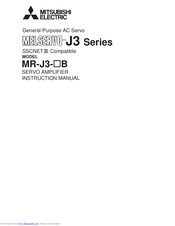
Mitsubishi Electric MR-J3-B Instruction Manual (225 pages)
MELSERVO-J3 Series Servo amplifier
Brand: Mitsubishi Electric
|
Category: Amplifier
|
Size: 8.01 MB
Table of Contents
Advertisement
Mitsubishi Electric MR-J3-B Instruction Manual (225 pages)
General-Purpose SSCNET III Compatible
Brand: Mitsubishi Electric
|
Category: Controller
|
Size: 8.22 MB
Table of Contents
Mitsubishi Electric MR-J3-B User Manual (4 pages)
Noise Filter Units for Servo Ampires
Brand: Mitsubishi Electric
|
Category: Recording Equipment
|
Size: 1.21 MB
Advertisement
Advertisement
Related Products
- Mitsubishi Electric MR-J3-B-RJ006
- Mitsubishi Electric MR-J3-T
- Mitsubishi Electric Melservo MR-J3-40B
- Mitsubishi Electric Melservo MR-J3-70B
- Mitsubishi Electric Melservo MR-J3-100B
- Mitsubishi Electric Melservo MR-J3-200B
- Mitsubishi Electric Melservo MR-J3-100B4
- Mitsubishi Electric Melservo MR-J3-200B4
- Mitsubishi Electric Melservo MR-J3- 350B4
- Mitsubishi Electric Melservo MR-J3-11KB4