Sign In
Upload
Manuals
Brands
Komatsu Manuals
Excavators
PC210NLC-8
Komatsu PC210NLC-8 Manuals
Manuals and User Guides for Komatsu PC210NLC-8. We have
2
Komatsu PC210NLC-8 manuals available for free PDF download: Shop Manual, Operation & Maintenance Manual
Komatsu PC210NLC-8 Shop Manual (1201 pages)
HYDRAULIC EXCAVATOR
Brand:
Komatsu
| Category:
Excavators
| Size: 69.18 MB
Table of Contents
Table of Contents
6
Table of Contents
17
Foreword and General Information
18
Safety Notice
18
General Precautions
18
Preparations for Work
18
Precautions for Sling Work and Making Signs
20
Precautions for Using Mobile Crane
21
Precautions for Using Overhead Hoist Crane
21
Selecting Wire Ropes
21
Wire Ropes
21
How to Read the Shop Manual
22
Filing Method
23
Symbols
23
Units
23
Explanation of Terms for Maintenance Standard
24
Standard Size and Tolerance
24
Standard Clearance and Standard Value
25
Standard Interference
25
Repair Limit and Allowable Value
25
Clearance Limit
25
Handling Electric Equipment and Hydraulic Component
26
Main Failures Occurring in Wiring Harness
26
Disconnections in Wiring
27
High-Pressure Water Entering Connector
27
Oil or Dirt Stuck to Connector
27
Disconnecting Connectors
28
When Removing from Clips
28
Connecting Connectors
29
Connecting DT Connectors
29
Drying Wiring Harness
30
Handling Controller
31
Points to Remember When Troubleshooting Electric Circuits
31
Points to Remember When Handling Hydraulic Equipment
32
Flushing Operations
33
Cleaning Operations
33
How to Read Electric Wire Code
34
Type, Symbol, and Material
34
Dimensions
35
Colour Codes Table
36
Types of Circuits and Colour Codes
36
Method of Disassembling and Connecting Push-Pull Type Coupler
37
Standard Tightening Torque Table
40
Table of Tightening Torques for Bolts and Nuts
40
Table of Tightening Torques for Split Flange Bolts
41
Table of Tightening Torques for O-Ring Boss Piping Joints
41
Table of Tightening Torques for O-Ring Boss Plugs
41
Table of Tightening Torques for Hoses
42
Table of Tightening Torques for 102, 107 and 114 Engine Series
42
Conversion Table
44
Millimetres to Inches
44
Kilogram to Pound
45
Litres to U.S. Gallons
45
Litres to U.K. Gallons
46
Temperature
48
Hydraulic Excavator
51
Specification and Technical Data
51
Specification Dimension Drawings
52
Specification and Technical Data
52
Working Range Diagram
53
Weight Table
58
Table of Fuel, Coolant and Lubricants
62
Structure, Function and Maintenance Standard
65
Engine and Cooling System
66
Engine Related Parts
66
Structure, Function and
66
Radiator, Oil Cooler, Aftercooler and Fuel Cooler
67
Diesel Particulate Filter
68
Diesel Particulate Filter - Component Parts
69
System Description
70
Regeneration
70
Power Train
73
Structure, Function and
74
Power Train
74
Final Drive
76
Swing Machinery
78
Swing Circle
82
Undercarriage and Frame
85
Track Frame and Recoil Spring
86
Structure, Function and
86
Undercarriage and Frame
86
Standard Shoe
87
Idler
88
Carrier Roller
90
Track Roller
91
Track Shoe
92
Triple Grouser Shoe
96
Swamp Shoe
96
Road Liner
96
Hydraulic System
99
Hydraulic Equipment Layout Drawing
100
Structure, Function and
100
Hydraulic System, Part 1
100
Hydraulic Tank and Filter
102
Hydraulic Pump
103
Operation of Pump
109
Control of Delivery
110
LS Valve
111
When the Control Valve Is Situated at Neutral
112
Action for the Direction of Maximizing the Pump Delivery
113
Action for the Direction of Minimizing the Pump Delivery
114
When Servo Piston Is Balanced
115
PC Valve
116
When Pump Controller Is Normal
117
Action of PC-EPC Valve Solenoid
117
Action of Spring
118
When the Main Pump Is under Heavy Load
123
LS (PC)-EPC Valve
124
When Signal Current Is 0
125
When Signal Current Is very Small
126
When Signal Current Is Maximum
126
Pilot Oil Filter
127
Control Valve
130
General View
131
Sectional View
134
Arm Valve
139
R.H. Travel Valve
139
Swing Valve
139
Boom Valve
141
Bucket Valve
141
L.H. Travel Valve
141
Outline of CLSS
143
Basic Principle
144
Pump Swash Plate Angle Control
144
LS Differential Pressure
144
Pressure Compensation Control
145
Functions and Operation by Valve
148
Hydraulic Circuit Diagram and the Name of Valves
148
Unload Valve
150
When the Unload Valve Is Actuating
150
Operation of Relief Valve
151
Introduction of LS Pressure
152
LS Bypass Valve
153
Pressure Compensation Valve
154
Integrated Pressure Compensation Valve
154
When Compensated
155
Pressure Compensation Valve Area Ratio
156
Pressure Compensation Valve Inner Shuttle Valve
157
In the Case of Travel
158
Boom Regeneration Circuit
159
Arm Regeneration Circuit
161
If the Cylinder Head Pressure Is Lower than the Bottom Pressure
162
Merge-Divider Valve
163
LS Select Valve
165
Self Pressure Reducing Valve
166
During Neutral and When Load Pressur (P2) Is Low
167
When Load Pressure (P2) Is High
167
When Abnormally High Pressure Is Generated
168
Travel Junction Valve
169
When Pilot Pressure Is Turned on
169
When Pilot Pressure Is Turned off
170
Travel PPC Shuttle Valve
171
Hydraulic Drift Prevention Valve
174
When the Piping Is Free of Burst
176
If the Piping Is Bursted
176
Quick Return Valve
179
When Arm out
179
When the Arm Is in Neutral
180
Lift Check Valve
181
While Engine Is Stopped
181
While Engine Is Running
181
Main Relief Valve
182
2-Stage Safety-Suction Valve
183
If Pilot Pressure Is on
184
Swing Motor
189
Hydraulic System, Part 3
189
Swing Holding Brake
192
Relief Valve Portion
193
Reverse Prevention Valve
194
Explanatory Drawing of Effects
195
Centre Swivel Joint
198
Travel Motor
201
Operation of Motor
204
At Slow Speed
204
At High Speed
205
Operation of Parking Brake
206
Brake Valve
208
Counterbalance Valve and Check Valve
208
Operation When Pressurized Oil Is Supplied
208
Operation of Brake During Travelling Downhill
209
Safety Valve
210
The Pump Pressure Rises, Providing a Large
211
PPC Valve
212
Work Equipment and Swing PPC Valve
212
Travel PPC Valve
216
Pressure Reducing Valve Function
219
Travel Signal
220
Steering Signal
220
Service PPC Valve (with EPC Valve)
225
EPC Valve
227
Service PPC Valve
230
Valve Control
232
ATT EPC Valve Assembly
234
Solenoid Valve
236
PPC Accumulator
238
Return Oil Filter
239
Attachment Circuit Selector Valve
240
Quick Coupler Control Valve
242
K50001~K50303
242
Function
245
Hydraulic Cylinder
246
Boom Cylinder
248
Arm Cylinder
248
Bucket Cylinder
248
Work Equipment
251
Dimensions of Components
252
Dimension of Arm
254
Dimension of Bucket
256
Cab and Its Attachments
259
Air Conditioner Piping
260
Electrical System
263
Engine Control
264
Starting Engine
264
Electrical System
264
Fuel Control Dial
265
Engine Controller
267
Coolant Temperature Sensor
269
Oil Pressure Switch
269
Rotation Sensor
270
Boost Pressure and Temperature Sensor
270
WIF (Water-In-Fuel Detection) Sensor
271
Engine Oil Level Sensor
271
Electrical Control System
272
Machine Control System Diagram
274
Engine and Pump Composite Control Function
276
Pump and Valve Control Function
280
LS Control Function
281
2-Stage Relief Function
281
Cut-Off Function
281
Power Maximizing Function
282
Auto-Deceleration Function
283
Auto-Warm-Up and Overheat Prevention Function
284
Auto-Warm-Up Function
285
Overheat Prevention Function
285
Swing Control Function
286
Swing Lock and Swing Holding Brake Function
287
Travel Control Function
288
Function to Control Pump During Travel
289
Travel Speed Change Function
289
System Component Parts
293
PPC Oil Pressure Switch
293
Oil Pressure Sensor
294
Pump Pressure Sensor
295
Quick Coupler Low Pressure Warning Switch
296
Auto Grease Pressure Switch
297
Monitor System
298
Machine Monitor
299
Input and Output Signals
300
Monitor Control, Display Portion
303
Monitor Items and Display
305
Switches
309
Buzzer Cancel Switch
309
Auto-Deceleration Switch
309
Guidance Icon and Function Switch
309
Working Mode Selector Switch
311
Travel Speed Selector Switch
311
Window Washer Switch
311
Air Conditioner Control Switch
311
Camera Screen Display Function
312
Maintenance Function
315
User Mode
317
Breaker/Attachment 1 Setting
317
Changing Breaker Mode Setting
318
Changing Attachment Mode 1 Setting
319
Attachment Setting Selection Screen
320
Attachment Flow Rate Setting Screen
320
Changing Attachment Mode 2 Setting
321
Message Display
323
Clock Adjustment
324
Time Setting
324
12/24 Display Mode
324
Language Setting
325
Economy Mode Adjustment
325
Summer Time
325
Idle Stop Guidance Function
326
Service Meter Check Function
327
Display LCD Check Function
327
User Code/Failure Code Display
328
Sensor
329
Hydraulic Oil Level Sensor
329
Fuel Level Sensor
330
Air Cleaner Clogging Sensor
330
Coolant Level Sensor
331
PPC Levers
332
LH PPC Lever
332
RH PPC Lever
333
KOMTRAX Terminal System
334
KOMTRAX Communication Modem
335
Auto Grease System
337
Outline of Auto Grease System
338
The Relief Valve
339
The Minimum-Level Switch
339
The Test Push-Button
339
Assembly
339
Components
339
Distribution Blocks and Metering Units
340
Grease Pressure Switch
341
The Display
341
The Greasing Cycle
342
The Pumping Phase
342
The Re-Grease Phase
342
The Pressure Decrease Phase
342
Greasing Cycle B
343
Pump Unit
343
Pump Unit Assembly
343
Magnetic Valve
344
Metering Units
345
Principle of Operation of the Metering Unit - First Phase
345
Principle of Operation of the Metering Unit - Second Phase
345
Principle of Operation of the Metering Unit - Third Phase
346
Principle of Operation of the Metering Unit - Fourth Phase
346
Introduction
348
The Length of the Greasing Cycles
349
Maximum Length of the Pumping Phase
349
Length of the Re-Grease and Pressure Decrease Phases
349
Reaction of the System to Grease Pressure Malfunctions
350
Display
350
Standard Service Value Table
353
Standard Value Table for Engine Related Parts
354
Standard Value Table for Chassis Related Parts
356
Hydraulic Drift of Travel
371
Boom Speed
371
Bucket Speed
371
Boom Time Lag
371
Arm Time Lag
372
Bucket Time Lag
372
Testing and Adjusting
375
Tools for Testing, Adjusting, and Troubleshooting
377
30 Testing and Adjusting
377
Testing and Adjusting, Part 1
377
Measuring Engine Speed
380
Preparation Work
380
Measuring Low Idle Speed
380
Measuring High Idle Speed
380
Measuring Intake Air Pressure (Boost Pressure)
381
Checking Exhaust Gas Colour
382
Checking Tools for Exhaust Gas Colour
382
Adjusting Valve Clearance
383
Measuring Tools for Valve Clearance
383
Valve Arrangement Drawing
383
Measuring Compression Pressure
385
Measuring Blow-By Pressure
387
Measuring Engine Oil Pressure
388
Handling Fuel System Parts
389
Releasing Residual Pressure from Fuel System
389
Measuring Fuel Pressure
390
Measuring Fuel Return Rate and Leakage
392
Bleeding Air from Fuel Circuit
394
Air Bleeding Route of Fuel Circuit
395
Checking Fuel Circuit for Leakage
396
Checking and Adjusting Air Conditioner Compressor Belt Tension
397
Measuring Swing Circle Bearing Clearance
398
Checking and Adjusting Track Shoe Tension
399
Increasing Tension
399
Decreasing Tension
400
Measuring Swing Relief Pressure
403
Travel Relief Pressure
403
Measuring Control Circuit Basic Pressure
405
Measuring and Adjusting Oil Pressure in Pump PC Control Circuit
406
Measuring PC-EPC Valve Output Pressure
407
Adjusting Pump PC Valve
408
Loosen Locknut
409
Measuring and Adjusting Oil Pressure in Pump LS Control Circuit
410
Measuring LS Differential Pressure
411
Measuring Solenoid Valve Output Pressure
416
Operation Table of PPC Lock Solenoid Valve
418
Operation Table of 2-Stage Relief Solenoid Valve
418
Operation Table of Swing Holding Brake Solenoid Valve
418
Operation Table of Travel Speed Shifting Solenoid Valve
418
Measuring PPC Valve Output Pressure
419
Connecting Points of PPC Piping
419
Measuring Tools for PPC Valve Output Pressure
420
Adjusting Play of Work Equipment and Swing PPC Valves
421
Measuring and Adjusting Quick Coupler Control Valve Output Pressure
422
Checking Parts Which Cause Hydraulic Drift of Work Equipment
423
Checking Arm Cylinder
423
Checking PPC Valve
424
Releasing Residual Pressure from Hydraulic Circuit
425
Releasing Residual Pressure from Swing Motor Circuit
425
Releasing Residual Pressure from Travel Motor Circuit
425
Measuring Oil Leakage
426
Measuring Oil Leakage from Arm Cylinder
426
Measuring Oil Leakage from Bucket Cylinder
427
Measuring Oil Leakage from Swing Motor
427
Measuring Oil Leakage from Travel Motor
428
Bleeding Air from each Part
429
Bleeding Air from Hydraulic Pump
429
Starting
430
Bleeding Air from Cylinder
430
Bleeding Air from Swing Motor
431
Bleeding Air from Travel Motor
431
Checking Oil Level and Starting Work
431
Checking Cab Tipping Stopper
432
Adjusting Mirrors
434
Installing Positions of Mirrors
435
Adjusting Mirrors (A1) and (B1)
435
Adjusting Mirrors (C1) and (D1)
435
Special Functions of Machine Monitor
440
Air Conditioner Specification
440
Heater Specification
441
Upper Section of Machine Monitor
441
Lower Section of Machine Monitor
441
Ordinary Functions and Special Functions of Machine Monitor
442
Classification of Operator Mode
443
Operator Mode (Outline)
444
Display Pattern of Operator Mode
444
Display of KOMATSU Logo
444
Display of Inputting Password
445
Display of Check before Starting
445
Display of Check of Breaker Mode
445
Display of Warning after Check before Starting
446
Display of Ending of Maintenance Interval
446
Display of Check of Working Mode and Travel Speed
446
Display of Ordinary Screen
446
Display of End Screen
447
Selection of Working Mode
447
Selection of Auto-Deceleration
447
Selection of Travel Speed
448
Precautions for Selecting Breaker Mode
448
Operation to Stop Alarm Buzzer
448
Operation of Windshield Wiper
449
Operation of Air Conditioner/Heater
449
Operation of Window Washer
449
Operation to Display Camera Mode
450
Operation to Display Clock and Service Meter
450
Check of Maintenance Information
451
Setting and Display of User Mode
451
Display of Energy-Saving Guidance
453
Display of Caution Monitor
453
Display of Automatic Judgment of Breaker
454
Display of User Code and Failure Code
454
Function of Checking Display of LCD
456
Function of Checking Service Meter
456
Function of Changing Attachment/Maintenance Password
457
Service Mode
459
Selection of Service Menu
459
Monitoring
460
Selecting Menu
460
Selecting Monitoring Items
460
Deciding Monitoring Items
460
Executing Monitoring
461
Holding Monitoring Information
461
Changing Machine Setting Mode
461
Monitoring Items Table
462
Abnormality Record
465
Abnormality Record (Electrical Systems)
466
Resetting Abnormality Record
466
Failure Codes Table
468
User Code
472
Alarm Buzzer
472
Component in Charge
472
Category of Record
472
Change of Maintenance Mode
475
Contents of Setting of each Maintenance Item
476
Function of Initializing All Items
476
Default (Working Mode with Key ON)
478
Default (Setting of Unit)
479
Default (With/Without Attachment)
480
Default (Setting of ECO Display)
484
Default (Setting of Breaker Detect)
485
Adjustment (Setting of Travel lo Speed)
488
Cylinder Cut-Out Operation
494
No Injection Cranking
495
Starting no Injection Cranking
496
Finishing no Injection Cranking
496
Prohibiting no Injection Cranking
496
Display of Fuel Consumption
497
Starting Measurement
497
Display and Function During Measurement
497
Finishing Measurement
497
Display of KOMTRAX Message
502
Handling High-Voltage Circuit of Engine Controller
506
30 Testing and Adjusting
506
Testing and Adjusting, Part 3
506
Preparation Work for Troubleshooting of Electrical System
507
Procedure for Testing Diodes
511
When Using Analog Circuit Tester
511
When Using Digital Circuit Tester
511
Pm Clinic Service
513
Items Related to Engine
514
Items Related to Oil Pressure
515
Check Sheet (PC210/LC/NLC-8/PC230NHD-8)
516
General Information on Troubleshooting
527
General Information on Troubleshooting
528
Points to Remember When Troubleshooting
528
Sequence of Events in Troubleshooting
529
Check before Troubleshooting
530
Classification and Procedures for Troubleshooting
531
Phenomena Looking Like Troubles and Troubleshooting Nos.
532
How to Read Electric Wire Code
535
Connection Table for Connector Pin Numbers
538
T-Boxes and T-Adapters Table
569
Troubleshooting by Failure Code
575
Locations of Fusible Links
584
Location of Fuse Box and Fuse Nos.
584
Troubles that Occur When Power Supply of Pump Controller Is Defective
585
Information in Troubleshooting Table
588
Failure Code [AB00KE] Charge Voltage Low
592
Failure Code [B@BAZG] Eng Oil Press. Low
594
Failure Code [B@BCNS] Eng Water Overheat
595
Failure Code [B@HANS] Hydr Oil Overheat
596
Failure Code [CA111] EMC Critical Internal Failure
596
Failure Code [CA115] Eng Ne and Bkup Speed Sens Error
597
Failure Code [CA122] Chg Air Press Sensor High Error
598
Circuit Diagram Related to Boost Pressure/Temperature Sensor
599
Failure Code [CA123] Chg Air Press Sensor Low Error
600
Failure Code [CA131] Throttle Sensor High Error
602
Failure Code [CA132] Throttle Sensor Low Error
604
Failure Code [CA144] Coolant Temp Sens High Error
606
Failure Code [CA145] Coolant Temp Sens Low Error
608
Circuit Diagram Related to Coolant Temperature Sensor
609
Failure Code [CA153] Chg Air Temp Sensor High Error
610
Failure Code [CA154] Chg Air Temp Sensor Low Error
612
Failure Code [CA155] Chg Air Temp High Speed Derate
614
Failure Code [CA187] Sens Supply 2 Volt Low Error
616
Failure Code [CA221] Ambient Press Sens High Error
618
Failure Code [CA222] Ambient Press Sens Low Error
620
Failure Code [CA227] Sens Supply 2 Volt High Error
622
Failure Code [CA238] Ne Speed Sens Supply Volt Error
624
Failure Code [CA271] IMV/PCV1 Short Error
625
Failure Code [CA272] IMV/PCV1 Open Error
626
Failure Code [CA322] Inj #1 (L#1) Open/Short Error
628
Failure Code [CA323] Inj #5 (L#5) Open/Short Error
630
Circuit Diagram Related to No. 5 Injector
631
Failure Code [CA324] Inj #3 (L#3) Open/Short Error
632
Circuit Diagram Related to No. 3 Injector
633
Failure Code [CA325] Inj #6 (L#6) Open/Short Error
634
Failure Code [CA331] Inj #2 (L#2) Open/Short Error
636
Circuit Diagram Related to No. 2 Injector
637
Failure Code [CA332] Inj #4 (L#4) Open/Short Error
638
Circuit Diagram Related to No. 4 Injector
639
Failure Code [CA342] Calibration Code Incompatibility
643
Failure Code [CA351] Injectors Drive Circuit Error
644
Circuit Diagram Related to Engine Controller
645
Failure Code [CA352] Sens Supply 1 Volt Low Error
646
Circuit Diagram Related to Sensor Power Supply 1
647
Failure Code [CA386] Sens Supply 1 Volt High Error
648
Failure Code [CA428] Water in Fuel Sensor High Error
650
Circuit Diagram Related to Water-In-Fuel Sensor
651
Failure Code [CA429] Water in Fuel Sensor Low Error
652
Failure Code [CA435] Eng Oil Press Sw Error
654
Failure Code [CA441] Battery Voltage Low Error
655
Circuit Diagram Related to Engine Controller Power Supply
657
Failure Code [CA442] Battery Voltage High Error
658
Failure Code [CA449] Rail Press very High Error
660
Failure Code [CA451] Rail Press Sensor High Error
662
Circuit Diagram Related to Common Rail Pressure Sensor
663
Failure Code [CA452] Rail Press Sensor Low Error
664
Failure Code [CA488] Chg Air Temp High Torque Derate
666
Failure Code [CA553] Rail Press High Error
666
Failure Code [CA559] Rail Press Low Error
667
Failure Code [CA689] Eng Ne Speed Sensor Error
668
Circuit Diagram Related to Engine Ne Speed Sensor
669
Failure Code [CA731] Eng Bkup Speed Sens Phase Error
670
Failure Code [CA757] All Continuous Data Lost Error
672
Failure Code [CA778] Eng Bkup Speed Sensor Error
674
Circuit Diagram Related to Engine Bkup Speed Sensor
675
Failure Code [CA1633] KOMNET Datalink Timeout Error
676
Circuit Diagram Related to CAN Communication
677
Failure Code [CA2185] Throt Sens Sup Volt High Error
678
Failure Code [CA2186] Throt Sens Sup Volt Low Error
679
Failure Code [CA2249] Rail Press very Low Error
680
Failure Code [CA2311] IMV Solenoid Error
682
Circuit Diagram Related to Supply Pump Actuator (Metering Unit)
683
Failure Code [CA2555] Grid Htr Relay Volt High Error
684
Failure Code [CA2556] Grid Htr Relay Volt Low Error
686
Failure Code [D19JKZ] Personal Code Relay Abnormality
688
Failure Code [D862KA] GPS Antenna Discon
690
Failure Code [DA25KP] 5V Sensor 1 Power Abnormality
691
Overload Alarm Monitor Non-Display Specification
691
Overload Alarm Monitor Display Specification
695
Failure Code [DA29KQ] Model Selection Abnormality
698
Circuit Diagram Related to Model Selection Connector (PC210, 210LC-8)
699
Circuit Diagram Related to Model Selection Connector (PC240LC-8)
701
Failure Code [DA2RMC] CAN Discon (Pump con Detected)
706
Failure Code [DAFGMC] GPS Module Error
708
Failure Code [DAFRMC] CAN Discon (Monitor Detected)
710
Failure Code [DGH2KB] Hydr Oil Sensor Short
712
Failure Code [DHPAMA] F Pump Press Sensor Abnormality
714
Circuit Diagram Related to F Pump Pressure Sensor
715
Failure Code [DHPBMA] R Pump Press Sensor Abnormality
716
Circuit Diagram Related to R Pump Pressure Sensor
717
Failure Code [DHS3MA] Arm Curl PPC Press Sensor Abnormality
718
Circuit Diagram Related to Arm Curl PPC Pressure Sensor
719
Failure Code [DHS4MA] Bucket Curl PPC Press Sensor Abnormality
720
Circuit Diagram Related to Bucket Curl PPC Pressure Sensor
721
Failure Code [DHS8MA] Boom Raise PPC Press Sensor Abnormality
722
Circuit Diagram Related to Boom Raise PPC Pressure Sensor
723
Failure Code [DHSAMA] Swing RH PPC Press Sensor Abnormality
724
Circuit Diagram Related to Swing Right PPC Pressure Sensor
725
Failure Code [DHSBMA] Swing LH PPC Press Sensor Abnormality
726
Circuit Diagram Related to Swing Left PPC Pressure Sensor
727
Failure Code [DHSDMA] Bucket Dump PPC Press Sensor Abnormality
728
Circuit Diagram Related to Bucket Dump PPC Pressure Sensor
729
Failure Code [DHX1MA] Overload Sensor Abnormality (Analog)
730
Circuit Diagram Related to Overload Alarm Pressure Sensor
731
Failure Code [DW43KA] Travel Speed Sol Discon
732
Circuit Diagram Related to Travel Speed Shifting Solenoid
733
Failure Code [DW43KB] Travel Speed Sol Short
734
Failure Code [DW45KA] Swing Brake Sol Discon
736
Circuit Diagram Related to Swing Holding Brake Solenoid
737
Failure Code [DW45KB] Swing Brake Sol Short
738
Failure Code [DW91KA] Travel Junction Sol Discon
740
Circuit Diagram Related to Travel Junction Solenoid
741
Failure Code [DW91KB] Travel Junction Sol Short
742
Failure Code [DWA2KA] Service Sol Discon
744
Failure Code [DWA2KB] Service Sol Short
745
Failure Code [DWK0KA] 2-Stage Relief Sol Discon
746
Failure Code [DWK0KB] 2-Stage Relief Sol Short
748
Circuit Diagram Related to 2-Stage Relief Solenoid
749
Failure Code [DXA8KA] PC-EPC (F) Sol Discon
753
Circuit Diagram Related to PC-EPC (F) Solenoid and PC-EPC (R) Solenoid
754
Failure Code [DXA8KB] PC-EPC (F) Sol Short
755
Failure Code [DXA9KA] PC-EPC (R) Sol Discon
757
Failure Code [DXA9KB] PC-EPC (R) Sol Short
759
Failure Code [DXE0KA] LS-EPC Sol Discon
761
Failure Code [DXE0KB] LS-EPC Sol Short
763
Failure Code [DXE4KA] Service Current EPC Discon
765
Failure Code [DXE4KB] Service Current EPC Short
767
Failure Code [DXE5KA] Merge-Divider Main Sol Discon
769
Circuit Diagram Related to Merge-Divider Main EPC Solenoid
770
Failure Code [DXE5KB] Merge-Divider Main Sol Short
771
Failure Code [DXE6KA] Merge-Divider LS Sol Discon
773
Failure Code [DXE6KB] Merge-Divider LS Sol Short
775
Failure Code [DY20KA] Wiper Working Abnormality
777
Circuit Diagram Related to Windshield Wiper and Window Washer
778
Failure Code [DY20MA] Wiper Parking Abnormality
779
Failure Code [DY2CKA] Washer Drive Discon
781
Failure Code [DY2CKB] Washer Drive Short
783
Failure Code [DY2DKB] Wiper Drive (For) Short
785
Failure Code [DY2EKB] Wiper Drive (Rev) Short
787
Failure Code [DXEAKA] Service Current EPC1 Discon
789
Failure Code [DXEAKB] Service Current EPC1 Short
790
Failure Code [DXE7KA] Service Current EPC2 Discon
791
Failure Code [DXE7KB] Service Current EPC2 Short
792
Failure Code [DXE8KA] Service Current EPC3 Discon
793
Failure Code [DXE8KB] Service Current EPC3 Short
794
Failure Code [DXE9KA] Service Current EPC4 Discon
795
Failure Code [DXE9KB] Service Current EPC4 Short
796
Failure Code [DFB1KZ] Service Lever Potentio 1 Abnormality
799
Failure Code [DFB2KZ] Service Lever Potentio 2 Abnormality
801
Failure Code [DFB5KZ] Service Lever Sub Potentio 1 Abnormality
803
Failure Code [DFB6KZ] Service Lever Sub Potentio 2 Abnormality
805
Failure Code [DFB3L8] Service Lever 1 Potentio Error
807
Failure Code [DFB4L8] Service Lever 2 Potentio Error
808
Troubleshooting of Electrical System
813
Before Carrying out Troubleshooting of Electrical System
815
Connection Table of Fuse Box
816
E-1 When Starting Switch Turned ON, Machine Monitor Displays
820
Circuit Diagram Related to Machine Monitor Power Supply
821
When Starting Switch Turned on
822
Circuit Diagram Related to Radiator Coolant Level Switch
823
Engine Does Not Start (Engine Does Not Turn)
825
Preheater Does Not Operate
828
Automatic Warm-Up System Does Not Operate
830
Precaution Lights up While Engine Is Running
834
Circuit Diagram Related to Air Cleaner Clogging Switch
837
Emergency Stop Item Lights up While Engine Is Running
839
Engine Coolant Temperature Gauge Does Not Indicate Normally
840
Hydraulic Oil Temperature Gauge Does Not Indicate Normally
841
Circuit Diagram Related to Hydraulic Oil Temperature Sensor
841
Fuel Level Gauge Does Not Indicate Normally
843
Circuit Diagram Related to Fuel Level Sensor
843
Fuel Level Gauge and Fuel Level Monitor
844
Machine Monitor Does Not Display some Items
845
Function Switch Does Not Work
845
Auto-Decelerator Does Not Operate Normally
846
Working Mode Does Not Change
847
Travel Speed Does Not Change
848
Alarm Buzzer Cannot be Stopped
849
Circuit Diagram for Quick Coupler System
851
Windshield Wiper and Window Washer Do Not Operate
852
Power Maximising Function Does Not Operate Normally
854
Circuit Diagram Related to Left Knob Switch
854
Swing Holding Brake Does Not Operate Normally
858
Travel Alarm Does Not Sound or Does Not Stop Sounding
860
Air Conditioner Does Not Operate Normally
862
Circuit Diagram Related to Air Conditioner
873
Machine Monitor Cannot be Set in Service Mode
874
Circuit Diagram Related to Travel PPC Pressure Switch and Travel Alarm
879
KOMTRAX System Does Not Operate Normally
884
Troubleshooting of Hydraulic and Mechanical System (H-Mode)
887
System Diagram of Hydraulic and Mechanical System
890
Engine Speed Lowers Extremely or Engine Stalls
895
Work Equipment, Swing, and Travel Systems Do Not Work
896
Abnormal Sound Comes out from Around Hydraulic Pump
896
Auto-Decelerator Does Not Operate
897
Fine Control Performance or Response Is Low
897
Speed or Power of Boom Is Low
898
Speed or Power of Arm Is Low
899
Speed or Power of Bucket Is Low
900
Work Equipment Does Not Move Singly
900
Hydraulic Drift of Work Equipment Is Large
901
Time Lag of Work Equipment Is Large
903
Power Maximizing Function Does Not Work
904
Machine Deviates During Travel
906
Travel Speed Is Low
907
Machine Is Not Steered Well or Steering Power Is Low
908
Travel Speed Does Not Change or Travel Speed Is Low/High
909
Travel System Does Not Move (Only One Side)
910
Upper Structure Does Not Swing
911
Swing Acceleration or Swing Speed Is Low
913
Upper Structure Overruns Remarkably When It Stops Swinging
914
Large Shock Is Made When Upper Structure Stops Swinging
915
Large Sound Is Made When Upper Structure Stops Swinging
915
Hydraulic Drift of Swing Is Large
916
Attachment Circuit Is Not Changed
917
Oil Flow in Attachment Circuit Cannot be Controlled
917
Attachment Installation Specification
917
Quick Coupler
918
Troubleshooting of Engine (S-Mode)
925
Method of Using Troubleshooting Chart
927
Exhaust Gas Is Black
928
Starting Performance Is Poor
930
Engine Does Not Start
931
Engine Does Not Turn
931
Exhaust Smoke Comes but Engine Does Not Start
933
Engine Does Not Pick up Smoothly
934
General Causes Why Engine Does Not Pick up Smoothly
934
Engine Stops During Operations
935
General Causes Why Engine Stops During Operations
935
Engine Does Not Rotate Smoothly
936
General Causes Why Engine Does Not Rotate Smoothly
936
Engine Lack Output (or Lacks Power)
937
General Causes Why Engine Lacks Output
937
Exhaust Smoke Is Black (Incomplete Combustion)
939
General Causes Why Exhaust Smoke Is Black
939
Oil Consumption Is Excessive (or Exhaust Smoke Is Blue)
940
General Causes Why Oil Consumption Is Excessive
940
Oil Becomes Contaminated Quickly
941
Fuel Consumption Is Excessive
942
Oil Is in Coolant
943
General Causes Why Oil Is in Coolant
943
Oil Pressure Drops
944
General Causes Why Oil Pressure Drops
944
Oil Level Rises (Entry of Coolant/Fuel)
945
General Causes Why Oil Level Rises
945
Coolant Temperature Becomes too High (Overheating)
946
General Causes Why Coolant Temperature Becomes too High
946
Abnormal Noise Is Made
947
General Causes Why Abnormal Noise Is Made
947
Vibration Is Excessive
948
General Causes Why Vibration Is Excessive
948
Diesel Particulate Filter System
949
Troubleshooting of Auto Grease System
951
Recognising Malfunctions
952
Malfunction Reports of the Display
952
Malfunction Finding Procedures
955
Disassembly and Assembly Related Information
959
Removal and Installation of Assemblies
960
List of Adhesives
962
Special Tool List
965
Sketches of Special Tools
970
A8 Plate
970
F1 Push Tool
970
F3 Plate
971
J2 Push Tool
971
J6 Push Tool
972
S Push Tool
972
Engine Cooling Related
975
Removal and Installation of Fuel Supply Pump Assembly
976
Removal and Installation of Fuel Injector Assembly
978
Fuel Injector Assembly
982
Rocker Arm and Crosshead Assembly
983
High-Pressure Pipes and Common Rail
984
Removal and Installation of Engine Front Seal
985
Vibration Damper
987
Removal and Installation of Engine Rear Seal
988
Removal and Installation of Cylinder Head Assembly
991
Cylinder Head Assembly
997
Removal and Installation of Radiator Assembly
1003
Removal and Installation of Aftercooler Assembly
1008
Removal and Installation of Fuel Cooler Assembly
1010
Disassembly and Assembly of Final Drive Assembly
1026
427-1510 Push Tool
1026
Block T
1026
Rod T
1026
Puller (30 Ton) T
1026
Pump T
1026
Hub Assembly
1028
Nut
1030
No.2 Carrier Assembly
1031
Wrench T
1034
Installer T
1034
427-1220 Push Tool T
1034
Block T
1034
Washer T
1034
Jack T
1034
Hydraulic Pump T
1034
Under Carriage and Frame
1057
Disassembly and Assembly of Carrier Roller
1058
Installer T
1058
Disassembly and Assembly of Track Roller Assembly
1061
Installer T
1061
Disassembly and Assembly of Idler Assembly
1063
Installer T
1063
Disassembly and Assembly of Recoil Spring
1066
Compressor (A) T
1066
Compressor (B) T
1066
Spacer Extension T
1066
Cylinder
1066
(686Kn{70Ton})
1066
Guide Bolt T
1066
Push Tool Kit (B) Q
1066
Bolt
1066
Push Tool Kit
1066
Removal and Installation of Sprocket
1068
Expansion and Installation of Track Shoe Assembly
1069
Development of Track Shoe
1069
Installation of Track Shoe
1070
Removal and Installation of Revolving Frame Assembly
1071
Removal and Installation of Center Swivel Joint Assembly
1076
Disassembly and Assembly of Center Swivel Joint Assembly
1078
Removal and Installation of Hydraulic Tank Assembly
1079
Removal and Installation of Control Valve Assembly
1082
Disassembly and Assembly of Control Valve Assembly
1087
Assembly of Control Valve Assembly
1089
Removal and Installation of Hydraulic Pump Assembly
1091
Removal and Installation of Oil Seal in Hydraulic Pump Input Shaft
1096
Disassembly and Assembly of Travel PPC Valve Assembly
1098
Disassembly and Assembly of Hydraulic Cylinder Assembly
1099
Disassembly of Cylinder Head Assembly
1101
Disassembly of Piston Assembly
1101
Piston Rod Assembly
1102
Disassembly and Assembly of Quick Coupler Valve
1105
Removal of Pressure Regulating Valve
1105
Removal of Solenoid and Directional Control Valve
1105
Removal and Installation of the Work Equipment Assembly
1108
Cab Related
1113
Removal and Installation of Operator's Cab Assembly
1114
Removal and Installation of Operator Cab Glass (Stuck Glass)
1117
Removal and Installation of Front Window Assembly
1127
Electric Components
1139
Removal and Installation of Air Conditioner Unit Assembly
1140
Removal and Installation of Monitor Assembly
1144
Removal and Installation of Pump Controller Assembly
1146
Removal and Installation of Engine Controller Assembly
1147
Hydraulic Diagrams and Drawings
1151
Hydraulic Circuit Diagram
1153
Electrical Diagrams and Drawings
1163
Electrical Circuit Diagram
1165
Advertisement
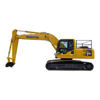
Komatsu PC210NLC-8 Operation & Maintenance Manual (41 pages)
HYDRAULIC EXCAVATOR
Brand:
Komatsu
| Category:
Excavators
| Size: 1.15 MB
Table of Contents
Safety Information
5
Directions of Machine
11
Breaking-In the New Machine
12
Product Information
13
Service Meter Location
14
Machine Serial Plates
15
Location of Safety Labels
32
Advertisement
Related Products
Komatsu PC210NLC-11
Komatsu PC210
Komatsu PC210LC-6K
Komatsu PC210LC-6
Komatsu PC210-8
Komatsu PC210LC-8
KOMATSU PC210-10 DEMOLITION BASE SPEC.
Komatsu PC210LC-11
Komatsu PC210-11
Komatsu GALEO PC210LC-7
Komatsu Categories
Excavators
Trucks
Compact Loader
Construction Equipment
Tractor
More Komatsu Manuals
Login
Sign In
OR
Sign in with Facebook
Sign in with Google
Upload manual
Upload from disk
Upload from URL