Sign In
Upload
Manuals
Brands
JVC Manuals
Recording Equipment
ShowView DELUXE HR-S9850MS
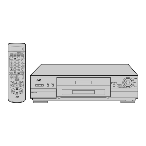
JVC ShowView DELUXE HR-S9850MS Manuals
Manuals and User Guides for JVC ShowView DELUXE HR-S9850MS. We have
1
JVC ShowView DELUXE HR-S9850MS manual available for free PDF download: Service Manual
JVC ShowView DELUXE HR-S9850MS Service Manual (94 pages)
MAGNETOSCOPE
Brand:
JVC
| Category:
Recording Equipment
| Size: 6.29 MB
Table of Contents
Table of Contents
3
Important Safety Precautions
4
1 Disassembly
7
Disassembly Flow Chart
7
How to Read the Disassembly and Assembly
7
Disassembly/Assembly Method
7
Service Position
10
How to Set the "Service Position
10
Precautions for Cassete Loding in the "Service Position
10
Mechanism Service Mode
10
How to Set the "Mechanism Service Mode
10
Jig RCU Mode
10
Setting the Jig RCU Mode
10
Setting the User RCU Mode
10
Emergency Display Function
11
Displaying the EMG Information
11
Clearing the EMG History
11
EMG Content Description
12
EMG Detail Information <1
13
EMG Detail Information <2
14
Servicing the Video Navigation Function
15
Copying the Video Navigation Data
15
Erasing the Video Navigation Data
15
Factory Setting Level During Shipment
16
2 Mechanism Adjustment
17
Before Starting Repair and Adjustment
17
Precautions
17
Checking for Proper Mechanical Operations
17
Manually Removing the Cassette Tape
17
Jigs and Tools Required for Adjustment
18
Maintenance and Inspection
19
Replacement of Major Parts
22
Before Starting Disassembling (Phase Matching between Mechanical Parts)
22
How to Set the "Mechanism Assembling Mode
22
Cassette Holder Assembly
22
Pinch Roller Arm Assembly
24
Guide Arm Assembly and Press Lever Assembly
24
A/C Head
24
Loading Motor
24
Capstan Motor
25
Pole Base Assembly (Supply or Take-Up Side)
25
Rotary Encoder
26
Clutch Unit
26
Change Lever Assembly, Direct Gear, Clutch Gear and Coupling Gear
26
Link Lever
27
Cassette Gear, Control Cam and Worm Gear
27
Control Plate
27
Loading Arm Gear (Supply or Take-Up Side) and Loading Arm Gear Shaft
28
Take-Up Lever, Take-Up Head and Control Plate Guide
29
Capstan Brake Assembly
29
Sub Brake Assembly (Take-Up Side)
29
Main Brake Assembly (Take-Up Side), Reel Disk (Take-Up Side) and Main Brake Assembly (Supply Side)
29
Tension Brake Assembly, Reel Disk (Supply Side) and Tension Arm Assembly
30
Idler Lever, Idler Arm Assembly
30
Stator Assembly
30
Rotor Assembly
30
Upper Drum Assembly
31
Compatibility Adjustment
32
FM Waveform Linearity
32
Height and Tilt of the A/C Head
33
A/C Head Phase (X-Value)
33
Standard Tracking Preset
34
Tension Pole Position
34
3 Electrical Adjustment
36
Precaution
36
Required Test Equipments
36
Required Adjustment Tools
36
Color (Colour) Bar Signal,Color (Colour) Bar Pattern
36
Switch Settings and Standard Precautions
36
EVR Adjustment
36
Servo Circuit
37
Switching Point
37
Slow Tracking Preset
37
Video Circuit
37
D/A Level
37
EE Y/PB y (S-VHS/VHS) Level
38
REC Color (Colour) Level
38
Video EQ (Frequency Response)
39
Auto Picture Initial Setting
39
Audio Circuit
39
Audio REC FM
39
PAL/SECAM Converter Circuit
40
Fh VCO
40
DEMOD Fo
40
Colour Difference Level
40
PAL Burst Position
41
Secam Bell
41
Charts and Diagrams
43
Notes of Schematic Diagram
43
Circuit Board Notes
44
Board Interconnections
45
Main (Video/Audio) Schematic Diagram
46
Main (Syscon) Schematic Diagram
47
Main (Sw.reg) Schematic Diagram
48
Main(Tuner) Schematic Diagram
49
Connection Schematic Diagram
50
Tbc(2M) Schematic Diagram
51
Terminal Schematic Diagram
52
Demodulator Schematic Diagram
53
S-Sub Schematic Diagram
54
Navigation Schematic Diagram
55
Schematic Diagrams
56
Secam Schematic Diagram[Hr-S9850Ms]
57
Secam Circuit Board[Hr-S9850Ms]
57
P/S Converter Schematic Diagram [Hr-S9850Ms]
58
P/S Converter Circuit Board[Hr-S9850Ms]
59
Main and Audio Erase Circuit Board
61
Sw/Display, Rec Safety, Jack, Adv.jog, Demodulator and S-Sub Circuit Boards
62
Digital/2M Circuit Board
63
Terminal Circuit Board
64
Navigation Circuit Board
65
Fdp Grid Assignment and Anode Connection
65
Remote Controller Schematic Diagram
66
Cpu Pin Function
66
Waveforms
67
Voltage Charts
68
Video Block Diagram
70
Audio Block Diagram
72
5 Parts List
73
Packing and Accessory Assembly <M1
73
Final Assembly <M2
75
Mechanism Assembly <M4
76
Electrical Parts List
78
Main Board Assembly <03
78
Digital/2M Board Assembly <05
85
Terminal Board Assembly <06
86
A/C Head Board Assembly <12
88
Demod Board Assembly <14
88
S-Sub Board Assembly <15
88
Navigation Board Assembly <19
89
Sw/Display Board Assembly <28
90
Rec Safety Board Assembly <32
90
Jack Board Assembly <36
91
Adv.jog Board Assembly <38
91
Audio Erase Board Assembly <46
91
Loading Motor Board Assembly <55
91
P/S Converter Board Assembly <87
91
Secam Board Assembly <88
94
Advertisement
Advertisement
Related Products
JVC HM -DR10000EU
JVC KD-DV5500 - Single DIN DVD/CD/WAV/MP3/WMA iPod/HD Radio Receiver/Satellite Ready
JVC DT-V100CGU - Hdtv Multi-format Monitor
JVC DT-V100CG
JVC DLA-X35BE
JVC DVL865EG
JVC DVL867EG
JVC DVX77EK
JVC ShowView LPT1132-001A
JVC ShowView LPT0923-001A
JVC Categories
Car Receiver
Camcorder
TV
VCR
Stereo System
More JVC Manuals
Login
Sign In
OR
Sign in with Facebook
Sign in with Google
Upload manual
Upload from disk
Upload from URL