Sign In
Upload
Manuals
Brands
Fujitsu Manuals
Microcontrollers
MB90F337
Fujitsu MB90F337 Manuals
Manuals and User Guides for Fujitsu MB90F337. We have
1
Fujitsu MB90F337 manual available for free PDF download: Hardware Manual
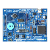
Fujitsu MB90F337 Hardware Manual (635 pages)
16-BIT MICROCONTROLLER
Brand:
Fujitsu
| Category:
Microcontrollers
| Size: 7.23 MB
Table of Contents
Table of Contents
10
Chapter 1 Overview
22
Feature of MB90335 Series
23
Block Diagram
28
Package Dimension
29
1.4 Pin Assignment
30
Pin Function
31
I/O Circuit Types
34
Handling of Device
37
Chapter 2 Cpu
40
Overview of the CPU
41
Memory Space
42
Linear Addressing
45
Bank Addressing
46
Multibyte Data in Memory Space
48
Registers
49
Accumulator (A)
52
User Stack Pointer (USP) and System Stack Pointer (SSP)
53
Processor Status (PS)
54
Program Counter (PC)
57
Bank Registers (PCB, DTB, USB, SSB, ADB)
58
Direct Page Register (DPR)
59
Register Bank
60
Prefix Codes
61
Interrupt Disable Instructions
64
Chapter 3 Interrupt
66
Outline of Interrupt
67
Interrupt Cause and Interrupt Vector
70
Interrupt Control Register and Peripheral Function
73
Interrupt Control Registers (ICR00 to ICR15)
75
Interrupt Control Register Functions
77
Hardware Interrupt
80
Operation of Hardware Interrupt
83
Operation Flow of Hardware Interrupt
85
Procedure for Using a Hardware Interrupt
86
Multiple Interrupts
87
Hardware Interrupt Processing Time
89
Software Interrupt
91
Interrupts by Extended Intelligent I/O Service (EI 2 OS)
93
Extended Intelligent I/O Service (EI 2 OS) Descriptor (ISD)
95
OS) Descriptor (ISD)
97
Operation of Extended Intelligent I/O Service (EI 2 OS)
100
Procedure for Use of Extended Intelligent I/O Service (EI 2 OS)
101
Extended Intelligent I/O Service (EI 2 OS) Processing Time
102
Exception Processing Interrupt
105
Interruption by Μdmac
106
Μdmac Function
107
Register of Μdmac
108
DMA Descriptor Window Register (DDWR)
115
Explanation of Operation of Μdmac
121
Exceptions
123
Stack Operation of Interrupt Processing
124
Program Example of Interrupt Processing
126
Delayed Interrupt Generation Module
130
Operation of Delayed Interrupt Generation Module
131
Chapter 4 Reset
132
Outline of Reset
133
Reset Factors and Oscillation Stabilization Wait Times
135
External Reset Pin
137
Reset Operation
138
Reset Factor Bit
140
State of each Pin at Reset
142
Chapter 5 Clock
144
Outline of Clock
145
Block Diagram of Clock Generation Section
147
Clock Select Register (CKSCR)
149
Clock Mode
151
Oscillation Stabilization Wait Time
153
Connection of Oscillator and External Clock
154
Chapter 6 Low-Power Consumption Mode
156
Outline of Low-Power Consumption Mode
157
Block Diagram of Low-Power Consumption Control Circuit
160
Low-Power Consumption Mode Control Register (LPMCR)
162
CPU Intermittent Operation Mode
165
Standby Mode
166
Sleep Mode
167
Time-Base Timer Mode
169
Stop Mode
170
State Transition Diagram
172
State of the Pin During Standby Mode, and Reset
174
Precautions When Using Low-Power Consumption Mode
175
Chapter 7 Mode Setting
178
Mode Setting
179
Mode Pins (MD2 to MD0)
180
Mode Data
181
Chapter 8 I/O Port
184
Functions of I/O Ports
185
I/O Port Register
186
Port Data Register (PDR0 to PDR2, PDR4 to PDR6)
187
Port Direction Register (DDR0 to DDR2, DDR4 to DDR6)
188
Other Registers
189
Chapter 9 Time-Base Timer
190
Overview of Time-Base Timer
191
Configuration of Time-Base Timer
193
Time-Base Timer Control Register (TBTC)
195
Interrupt of Time-Base Timer
197
Operations of Time-Base Timer
198
Precautions When Using Time-Base Timer
200
Program Example of Time-Base Timer
202
Chapter 10 Watchdog Timer
204
Overview of Watchdog Timer
205
Watchdog Timer Control Register (WDTC)
206
Configuration of Watchdog Timer
208
Operations of Watchdog Timer
209
Precautions When Using Watchdog Timer
211
Program Examples of Watchdog Timer
212
Chapter 11 Usb Function
214
Overview of USB Function
215
Block Diagram of USB Function
216
Registers of USB Function
217
UDC Control Register (UDCC)
220
EP0 Control Register (EP0C)
223
EP1 to EP5 Control Register (EP1C to EP5C)
225
Time Stamp Register (TMSP)
229
UDC Status Register (UDCS)
230
UDC Interruption Enable Register (UDCIE)
233
EP0I Status Register (EP0IS)
235
EP0O Status Register (EP0OS)
237
EP1 to EP5 Status Register (EP1S to EP5S)
240
EP0 to EP5 Data Register (EP0DT to EP5DT)
244
Operation Explanation of USB Function
245
Detecting Connection and Disconnection
248
Each Register Operation When Command Responds
250
STALL Response and Release
252
Suspend Function
256
Wake-Up Function
257
DMA Transfer Function
258
NULL Transfer Function
262
Chapter 12 Usb Host
264
Feature of USB HOST
265
Restriction on USB HOST
266
Block Diagram of USB HOST
267
Register of USB HOST
268
Host Control Register 0,1(HCNT0/HCNT1)
271
Host Interruption Register (HIRQ)
275
Host Error Status Register (HERR)
278
Host State Status Register (HSTATE)
281
SOF Interruption FRAME Comparison Register (HFCOMP)
284
Retry Timer Setting Register (HRTIMER)
285
Host Address Register (HADR)
286
EOF Setting Register (HEOF)
287
FRAME Setting Register (HFRAME)
288
Host Token Endpoint Register (HTOKEN)
289
Operation of USB HOST
291
Connection of Device
292
Reset of USB Bus
294
Token Packet
295
Data Packet
297
Handshake Packet
298
Retry Function
299
SOF Interrupt
300
Error Status
302
Packet End
303
Suspend Resume
304
Cutting of Device
307
Each Token Flow Chart of USB HOST
308
Chapter 13 Pwc Timer
310
Overview of PWC Timer
311
Register of PWC Timer
313
PWC Control Status Register (PWCSR)
314
PWC Data Buffer Register (PWCR)
319
PWC Ratio of Dividing Frequency Control Register (DIVR)
320
Movement of PWC Timer
321
Operation of PWM Timer Functions
322
Operation of Pulse Width Measurement Function
323
Count Clock Selection and Operation Mode Selection
324
Startup and Stop of Timer/Pulse Width Measurement
326
Operation of Timer Mode
328
Operation of Pulse Width Measurement Mode
331
Precautions When Using PWC Timer
336
Chapter 14 16-Bit Reload Timer
338
Overview of 16-Bit Reload Timer
339
Function of 16-Bit Reload Timer
340
Block Diagram of 16-Bit Reload Timer
342
Registers of 16-Bit Reload Timer
343
Timer Control Status Register 0 (TMCSR0)
344
16-Bit Timer Register 0 (TMR0)/16-Bit Reload Register 0 (TMRLR0)
348
Movement of 16-Bit Reload Timer
350
State Transition of Counter Operation
351
Operation of Internal Clock Mode (Reload Mode)
352
Operation of Internal Clock Mode (Single Shot Mode)
355
Event Count Mode
358
Chapter 15 8/16-Bit Ppg Timer
360
Overview of 8/16-Bit PPG Timer
361
Block Diagram of 8/16-Bit PPG Timer
362
Registers of 8/16-Bit PPG Timer
364
PPG0/PPG2 Operation Mode Control Register (PPGC0/PPGC2)
365
PPG1/PPG3 Operation Mode Control Register (PPGC1/PPGC3)
367
PPG0 to PPG3 Output Control Register (PPG01/PPG23)
370
PPG Reload Registers (PRLL0 to PRLL3, PRLH0 to PRLH3)
372
Operation of 8/16-Bit PPG Timer
373
Chapter 16 Dtp/External Interrupt
378
Overview of Dtp/External Interrupt
379
Register of Dtp/External Interrupt
380
Operation of Dtp/External Interrupt
383
Precaution of Using Dtp/External Interrupt
385
Chapter 17 Extended I/O Serial Interface
388
Outline of Extended I/O Serial Interface
389
Register in Extended I/O Serial Interface
390
Serial Mode Control Status Register (SMCS)
391
Serial Data Register (SDR)
395
Communication Prescaler Control Register (SDCR)
396
Operation of Extended I/O Serial Interface
398
Shift Clock Mode
399
Operation State of Serial I/O
400
Start/Stop Timing of Shift Operation and Timing of I/O
402
Interrupt Function
404
Chapter 18 Uart
406
Overview of UART
407
Block Diagram of UART
409
UART Pins
412
Register of UART
413
Serial Control Register 0, 1 (SCR0, SCR1)
414
Serial Mode Register 0, 1 (SMR0, SMR1)
416
Serial Status Register 0, 1 (SSR0, SSR1)
418
Serial Input Data Register 0, 1 (SIDR0, SIDR1) and Serial Output Data Register 0, 1 (SODR0, SODR1)
421
UART Prescaler Control Register 0, 1 (UTCR0, UTCR1) and UART Prescaler Reload Register 0, 1 (UTRLR0, UTRLR1)
423
UART Interrupt
425
Receive Interrupt Generation and Flag Set Timing
427
Transmit Interrupt Generation and Flag Set Timing
429
UART Baud Rate
431
Baud Rate of the UART Internal Clock Using the Dedicated Baud Rate Generator
432
Baud Rate of the External Clock Using the Dedicated Baud Rate Generator
433
Baud Rate of the External Clock (One-To-One Mode)
434
Explanation of Operation of UART
435
Operation in Asynchronous Mode (Operation Mode 0 or Operation Mode1)
437
Operation in Synchronous Mode (Operation Mode 2)
440
Bidirectional Communication Function (Normal Mode)
443
Master/Slave Mode Communication Function (Multi-Processor Mode)
445
Notes on Using UART
448
Example of UART Programming
449
Chapter 19 I 2 C Interface
452
I 2 C Interface Outline
453
I 2 C Interface Register
455
I 2 C Bus Status Register 0 (IBSR0)
456
I 2 C Bus Control Register 0 (IBCR0)
458
I 2 C Bus Clock Control Register 0 (ICCR0)
464
I 2 C Bus Address Register 0 (IADR0)
466
I 2 C Bus Data Register 0 (IDAR0)
467
I 2 C Interface Operation
468
Transfer Flow of I C Interface
470
Mode Flow of I C Interface
472
Operation Flow of I 2 C Interface
473
Chapter 20 Rom Mirror Function Selection Module
476
Overview of ROM Mirror Function Select Module
477
ROM Mirror Function Select Register (ROMM)
478
Chapter 21 Address Match Detection Function
480
Overview of Address Match Detection Function
481
Block Diagram of Address Match Detection Function
482
Configuration of Address Match Detection Function
483
Program Address Detection Control Status Register (PACSR)
484
Program Address Detection Registers (PADR0, PADR1)
486
Explanation of Operation of Address Match Detection Function
488
Example of Using Address Match Detection Function
489
Program Example of Address Match Detection Function
494
Chapter 22 Dual Operation Flash Memory
496
Overview of Dual Operation Flash Memory
497
Sector/Bank Configuration of Flash Memory
499
Registers of Flash Memory
501
Flash Memory Control Status Register (FMCS)
502
Flash Memory Write Control Register (FWR0/FWR1)
505
Sector Switching Register (SSR0)
510
How to Start Automatic Algorithm of Flash Memory
512
Reset Vector Addresses in Flash Memory
514
Check the Execution State of Automatic Algorithm
515
Data Polling Flag (DQ7)
517
Toggle Bit Flag (DQ6)
519
Timing Limit over Flag (DQ5)
520
Sector Erase Timer Flag (DQ3)
521
Details of Programming/Erasing Flash Memory
522
Read/Reset State in Flash Memory
523
Data Programming to Flash Memory
524
Data Erase from Flash Memory (Chip Erase)
526
Erasing any Data in Flash Memory (Sector Erasing)
527
Sector Erase Suspension
529
Sector Erase Resumption
530
Operation of Dual Operation Flash Memory
531
CHAPTER 23 EXAMPLE of CONNECTING SERIAL WRITING
534
Basic Configuration
535
Oscillation Clock Frequency and Serial Clock Input Frequency
537
Flash Microcontroller Programmer System Configuration
538
Example of Connecting Serial Writing
539
Example Connection in Single-Chip Mode (When Using User Power)
540
Example of Minimum Connection to Flash Microcontroller Programmer (When Using User Power)
542
Appendix
544
APPENDIX A Memory Map
545
APPENDIX B Instructions
557
Instruction Types
558
Addressing
559
Direct Addressing
561
Indirect Addressing
567
Execution Cycle Count
575
Effective Address Field
578
How to Read the Instruction List
579
F 2 MC-16LX Instruction List
582
Instruction Map
596
Index
618
Advertisement
Advertisement
Related Products
Fujitsu MB90F481B
Fujitsu MB90F482B
Fujitsu MB90F488B
Fujitsu MB90F489B
Fujitsu MB90F428
Fujitsu MB90F428A
Fujitsu MB905 Series
Fujitsu MB906 Series
Fujitsu MB90V420
Fujitsu MB90V330A
Fujitsu Categories
Air Conditioner
Laptop
Server
Scanner
Storage
More Fujitsu Manuals
Login
Sign In
OR
Sign in with Facebook
Sign in with Google
Upload manual
Upload from disk
Upload from URL