Sign In
Upload
Manuals
Brands
CANON Manuals
All in One Printer
LASERBASE MF3110
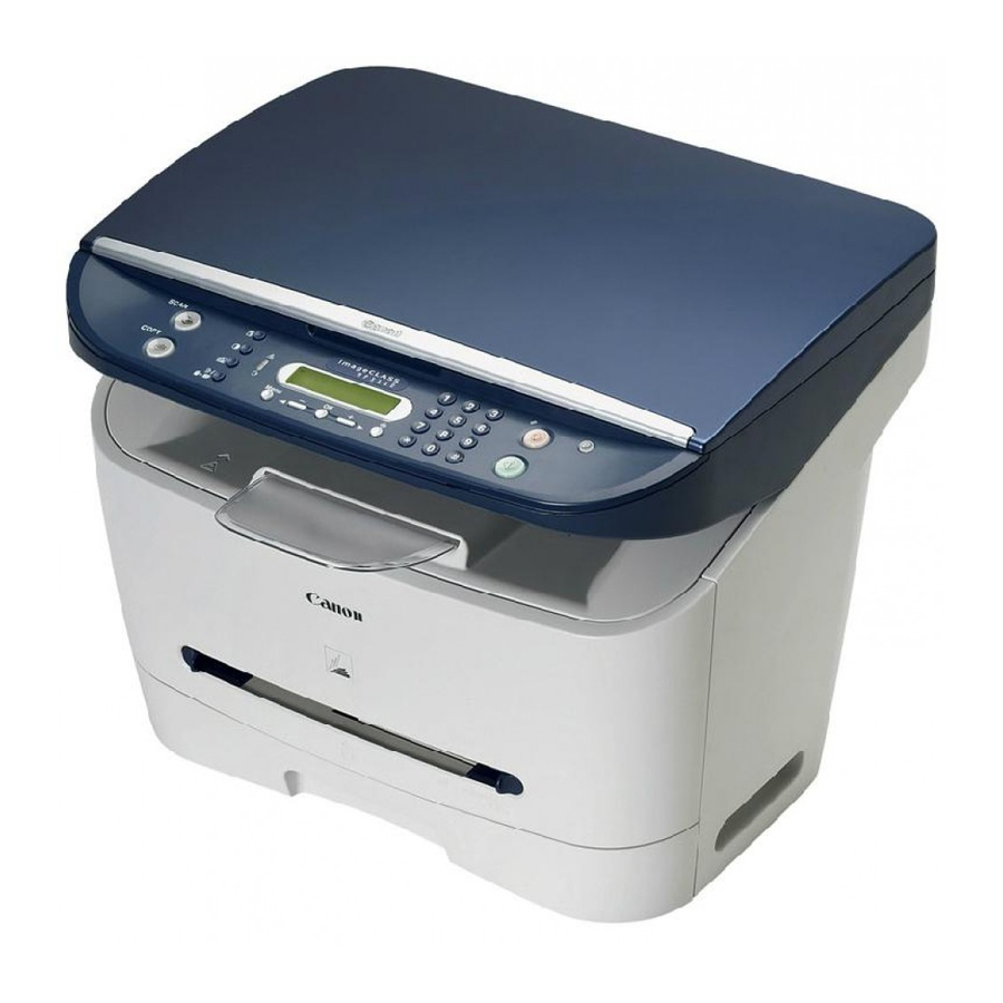
CANON LASERBASE MF3110 Manuals
Manuals and User Guides for CANON LASERBASE MF3110. We have
3
CANON LASERBASE MF3110 manuals available for free PDF download: Service Manual, User Manual
Canon LASERBASE MF3110 Service Manual (176 pages)
MF3110 Series
Brand:
Canon
| Category:
All in One Printer
| Size: 5.41 MB
Table of Contents
Section 1
7
Service Manual
1
Table of Contents
7
Chapter 1 PRODUCT DESCRIPTION
11
Section 2
13
Detailed Specifications 1
13
Product Specifications 1
13
Product Specifications
15
1Product Specifications
15
Detailed Specifications
17
1Printing Speed
17
2Stack Upon Delivery
17
3System Requirements for Printer Driver
18
Names of Parts
19
1External View
19
2Operation Panel
19
2Operation Panel
21
Safety
22
1Safety of Laser Light
22
2Handling the Laser Unit
22
3Safety of Toner
23
Chapter 2 TECHNICAL REFERENCE
25
Section 3
27
Document Feed and Exposure System 2
27
Image Formation 2
27
Laser Exposure 2
27
Overview/Configuration 2
27
Document Feed and Exposure System
29
Overview/Configuration
29
Overview
29
Laser Exposure
30
Overview/Configuration
30
Overview
30
Image Formation
32
Overview/Configuration
32
Overview
32
Pickup and Feed System
34
Overview/Configuration
34
Overview
34
Detection Jams
35
Jam Detection Outline
35
Delay Jams
36
Other Jams
36
Stationary Jams
36
Fixing Unit
37
Overview/Configuration
37
Overview
37
Protective Function
38
Protective Mechanisms
38
Detecting a Fault in the Fixing Assembly
39
External and Controls
40
Power Supply
40
Energy Saving Function
40
Section 4
43
External and Controls System 3
43
Front Cover 3
43
Rear Cover 3
43
Right Cover 3
43
Top Cover 3
43
Document Feed/Exposure System 3
44
High Voitage Power Supply PCB 3
44
Paper Delivery Sensor 3
44
Scanner Unit 3
44
Top Sensor 3
44
CCD Unit 3
45
Flatbed Motor Unit 3
45
Image Formation System 3
45
Laser Exposure System 3
45
Laser/Scanner Unit 3
45
Cassette Pickup Solenoid 3
46
Cassette Separation Pad 3
46
Manual Pickup Solenoid 3
46
Paper Feed Roller 3
46
Fixing System 3
47
Gear Unit 3
47
Main Motor 3
47
Chapter 3 ޓDISASSEMBLY and ASSEMBLY
49
External and Controls System
49
Front Cover
49
Rear Cover
49
Removing the
49
Removing the Cassette
49
Removing the Right Cover
49
Removing the Cassette
50
Removing the Left Cover
50
Removing the Rear Cover
50
Top Cover
50
Removing the Left Cover
51
Removing the Scanner Unit
51
Left Cover
52
Removing the Cassette
52
Removing the Right Cover
52
Right Cover
52
Operation Panel Unit
53
Removing the Left Cover
53
Removing the Right Cover
53
Removing the Rear Cover
54
Removing the Scanner Unit
54
Removing the Cassette
55
SCNT Board
55
Removing the Left Cover
56
Removing the Rear Cover
56
Removing the Right Cover
56
Removing the Board Unit
57
Removing the Scanner Unit
57
ECNT Board
58
Removing the Cassette
58
Removing the ECNT Board
58
Removing the Left Cover
58
Removing the SCNT Board
58
Power Supply PCB
59
Removing the Cassette
59
High Voitage Power Supply PCB
61
Removing the Right Cover
61
Removing the Left Cover
62
Removing the Power Supply Shield Plate
62
Removing the Rear Cover
62
Removing the Cassette
63
Removing the High Voltage Power Supply Board
63
Removing the Power Supply Assembly
63
Top Sensor
63
Removing the Left Cover
64
Removing the Right Cover
64
Removing the
65
Removing the Rear Cover
65
Removing the Scanner Unit
65
Removing the Left Frame
66
Removing the Plate
66
Removing the Right Frame
66
Removing the Top Cover
66
Removing the Power Supply Assembly
67
Removing the Power Supply Shield Plate
67
Removing the Top Sensor
67
Paper Delivery Sensor
68
Removing the Cassette
68
Removing the Left Cover
68
Removing the Right Cover
68
Removing the
69
Removing the Power Supply Shield Plate
69
Removing the Rear Cover
69
Removing the Scanner Unit
69
Removing the Paper Delivery Sensor
70
Removing the Plate
70
Document Feed/Exposure System
71
Removing the Cassette
71
Removing the Left Cover
71
Removing the Right Cover
71
Scanner Unit
71
Removing the Cassette
72
Removing the Rear Cover
72
Removing the Right Cover
72
Removing the Scanner Unit
72
Scanner Cover Unit
72
Removing the Left Cover
73
Removing the Rear Cover
73
Removing the Scanner Unit
73
Removing the Board Unit
74
Removing the Operation Panel Unit
74
CCD Unit
75
Removing the Cassette
75
Removing the Left Cover
75
Removing the Right Cover
75
Removing the Scanner Cover Unit
75
Removing the Board Unit
76
Removing the Scanner Unit
76
Removing the Flatbed Motor Unit
77
Removing the Operation Panel Unit
77
Removing the Scanner Cover Unit
77
Flatbed Motor Unit
78
Removing the Cassette
78
Removing the CCD Unit
78
Removing the Right Cover
78
Removing the Left Cover
79
Removing the Rear Cover
79
Removing the Scanner Unit
79
Removing the Board Unit
80
Removing the Operation Panel Unit
80
Removing the Scanner Cover Unit
80
Removing the Flatbed Motor Unit
81
Laser Exposure System
82
Laser/Scanner Unit
82
Removing the Cassette
82
Removing the Left Cover
82
Removing the Right Cover
82
Removing the Rear Cover
83
Removing the Scanner Unit
83
Removing the Top Cover
83
Removing the Laser/Scanner Unit
84
Image Formation System
85
Removing the Transfer Charging Roller
85
Transfer Charging Roller
85
Pickup and Feeding System
86
Cassette Pickup Roller
86
Removing the Cassette
86
Removing the Left Cover
86
Removing the Right Cover
86
Removing the
87
Removing the Rear Cover
87
Removing the Scanner Unit
87
Removing the Left Frame
88
Removing the Plate
88
Removing the Right Frame
88
Removing the Top Cover
88
Removing the Gear Unit
89
Removing the Power Supply Assembly
89
Removing the Power Supply Shield Plate
89
Cassette Pickup Solenoid
90
Removing the Cassette
90
Removing the Cassette Pickup Roller
90
Removing the Right Cover
90
Removing the Tooth Missing Gear
90
Removing the
91
Removing the Left Cover
91
Removing the Rear Cover
91
Removing the Right Frame
92
Removing the Scanner Unit
92
Removing the Top Cover
92
Removing the Left Frame
93
Removing the Plate
93
Removing the Power Supply Assembly
93
Removing the Power Supply Shield Plate
93
Cassette Separation Pad
94
Removing the Cassette Pickup Solenoid
94
Removing the Cassette Separation Pad
94
Removing the Rear of the Cassette
94
Paper Feed Roller
95
Removing the Cassette
95
Removing the Left Cover
95
Removing the Right Cover
95
Removing the
96
Removing the Rear Cover
96
Removing the Scanner Unit
96
Removing the Left Frame
97
Removing the Plate
97
Removing the Right Frame
97
Removing the Top Cover
97
Removing the Gear Unit
98
Removing the Power Supply Assembly
98
Removing the Power Supply Shield Plate
98
Removing the Manual Stay
99
Removing the Paper Feed Guide
99
Removing the Tooth Missing Gear
99
Manual Pickup Solenoid
100
Removing the Cassette
100
Removing the Left Cover
100
Removing the Paper Feed Roller
100
Removing the Right Cover
100
Removing the
101
Removing the Rear Cover
101
Removing the Scanner Unit
101
Removing the Left Frame
102
Removing the Plate
102
Removing the Right Frame
102
Removing the Manual Pickup Solenoid
103
Removing the Power Supply Assembly
103
Removing the Power Supply Shield Plate
103
Main Motor
104
Removing the Cassette
104
Removing the Left Cover
104
Removing the Right Cover
104
Removing the
105
Removing the Rear Cover
105
Removing the Scanner Unit
105
Removing the Left Frame
106
Removing the Plate
106
Removing the Right Frame
106
Removing the Top Cover
106
Removing the Main Motor
107
Removing the Power Supply Assembly
107
Removing the Power Supply Shield Plate
107
Gear Unit
108
Removing the Cassette
108
Removing the Gear Unit
108
Removing the Right Cover
108
Fixing System
109
Fixing Film Unit
109
Removing the Cassette
109
Removing the Left Cover
109
Removing the Right Cover
109
Removing the
110
Removing the Rear Cover
110
Removing the Scanner Unit
110
Removing the Left Frame
111
Removing the Plate
111
Removing the Right Frame
111
Removing the Fixing Film Unit
112
Removing the Power Supply Shield Plate
112
Fixing Pressure Roller
113
Removing the Cassette
113
Removing the Left Cover
113
Removing the Right Cover
113
Removing the
114
Removing the Rear Cover
114
Removing the Scanner Unit
114
Removing the Left Frame
115
Removing the Plate
115
Removing the Right Frame
115
Removing the Top Cover
115
Periodically Replaced Parts 4
121
Chapter 4 ޓMAINTENANCE and INSPECTION
123
Periodically Replaced Parts
123
1Parts Requiring Periodical Replacement
123
Consumables
124
Consumable 4
124
Periodical Service
125
1Items Requiring Scheduled Servicing
125
Cleaning
126
1Items Requiring Cleaning
126
Cleaning Method (External Covers) 4
127
Cleaning Method (Scanning Unit) 4
127
Cleaning Method (Printer Unit) 4
128
Lubrications
129
1Areas Requiring Application of Grease
129
Delivery Idler Gear 4
129
Fixing Drive Transmission Gear 4
129
Large Gear Bushing R 4
129
2Delivery Idler Gear
130
3Fixing Drive Transmission Gear
131
4Large Gear Bushing
131
5Large Gear
132
6Feed Gear
132
7Internal Gear
133
8Large Gear Deceleration Gear/Plate
134
9Main Motor
135
Drive Releasing Arm
136
Fu Delivery Roller
137
Feed Deceleration Gear
138
Pickup Idler Gear
138
Fixing Deceleration Gear
139
FD Delivery Roller 4
140
Large Gear Bushing F 4
140
Cassette Pickup Roller 4
141
Pressure Roller 4
141
CCD Shaft 4
142
Wheel Shaft 4
142
Chapter 5 TROUBLE SHOOTING
143
Section 5
145
Phenomenon Table 5
145
Phenomenon Table
147
1Symptoms
147
Countermeasure
148
Control Panel Related
148
Image Faults
148
Malfunction
148
Malfunction/Faulty Detection
148
Partially Blank/Streaked
148
Faulty Printing/Scanning Result
149
Jam (Main Unit)
149
Jam When Feeding Paper from a Cassette
149
Printing/Scanning
149
The Machine Identifies a Jam When Its Power Is Turned off and then on with Paper in Its Manual Feed Section
149
Measurement and Adjustment
150
Basic Adjustments
150
Items of Adjustment
150
Service Tools
151
1Special Tools
151
Error Code
152
E000 Fixing Unit Failure
152
Error Code Outline
152
Outline
152
Service Error Code
152
Unique Remedies Service Error Codes
152
E100 Laser/Scanner Unit Failure
153
Service Mode
154
Outline
154
Service Data Setting
154
Service Data Entry Method
155
Service Data Flowchart
155
Outline
158
Service Soft Switch Settings (SSSW)
158
Sssw Sw14
159
Overview
160
Rom
160
ROM Management (ROM)
160
Test Mode (TEST)
160
DRAM Test
162
Print Test
163
Faculty Test
164
Chapter 6 APPENDIX
169
Outline of Electrical Components 6
171
Sensor 6
171
Pcbs 6
171
Outline of Electrical Components
173
Arrangement of Sensors and Switches
173
Sensor
173
Arrangement of Pcbs
174
Pcbs
174
Advertisement
CANON LASERBASE MF3110 User Manual (75 pages)
Brand:
CANON
| Category:
All in One Printer
| Size: 2.98 MB
Table of Contents
Manuals for the Machine
2
Quick Reference Guide
2
Table of Contents
5
Preface
8
How to Use this Manual
8
Symbols Used in this Manual
8
Keys Used in this Manual
8
Messages Displayed in the LCD
8
Chapter 1 Introduction
9
Customer Support
9
Main Components of the Machine
9
Operation Panel
11
Standby Display
12
Energy Saver Mode
13
Setting the Energy Saver Mode Manually
13
Restoring from the Energy Saver Mode Manually
13
Chapter 2 Paper Handling
14
Print Media Requirements
14
Printing Areas
15
Loading Paper
16
Loading Paper in the Cassette
16
Loading Paper in the Multi-Purpose Feeder
19
Loading an Envelope in the Multi-Purpose Feeder
20
Specifying the Paper Size and Type (Common for Cassette and Multi-Purpose Feeder)
21
Specifying the Paper Size
21
Specifying the Paper Type
22
Orientation of the Document and the Paper Loading
22
Selecting the Paper Output Area
23
Paper Type and Paper Output Area
23
Face down Paper Output Area
24
Face up Paper Output Area
24
Chapter 3 Document Handling
25
Document Requirements
25
Scanned Area of a Document
26
Placing a Document on the Platen Glass
26
Chapter 4 Printing from Your Computer
28
Before Printing
28
Printing Documents
28
Canceling Printing
29
More Information
29
Chapter 5 Copying
30
Documents You Can Copy
30
Making Copies
30
Setting Enlarging/Reducing
31
Enlarging/Reducing Using Preset Copy Ratios
31
Enlarging/Reducing Using Custom Copy Ratios
31
Improving Copied Image
32
Adjusting the Image Quality (Resolution)
32
Adjusting the Exposure (Density)
32
Special Features
33
Collate Copy
33
On 1 Copy
34
Reserve Copy
35
Chapter 6 Scanning
36
Before Scanning
36
Scanning Methods
36
More Information
37
Chapter 7 System Monitor
38
Checking the Status of the Jobs Stored in the Machine
38
Confirming and Deleting a Copy Job
38
Confirming and Deleting a Print Job
39
Chapter 8 Maintenance
40
Periodic Cleaning
40
Cleaning the Exterior
40
Cleaning the Scanning Area
40
When to Replace the Cartridge
41
Print Yield
42
Handling and Storing the Cartridge
42
Storage Precautions
43
Replacing the Cartridge
44
Repacking and Transporting Your Machine
47
Carrying the Machine by the Sides
47
Transporting the Machine by Car
48
Chapter 9 Troubleshooting
49
Clearing Jams
49
LCD Messages
55
Paper Feeding Problems
57
Copying Problems
60
Print Quality Problems
60
Printing Problems
62
Scanning Problems
63
General Problems
63
If You Cannot Solve the Problem
65
Chapter 10 Machine Settings
66
Accessing the Machine Settings
66
Menu Descriptions
66
Paper Settings
66
Common Settings
67
Copy Settings
68
Printer Settings
69
Timer Settings
69
Chapter 11 Appendix
70
Specifications
70
Index
72
Canon LASERBASE MF3110 Service Manual (8 pages)
Brand:
Canon
| Category:
All in One Printer
| Size: 0.54 MB
Table of Contents
Chapter 4 Maintenance and Inspection
3
Chapter 5 Trouble Shooting
4
Chapter 6 Appendix
4
Parts Catalog
6
Assembly Location Diagram
8
Board Ass'y
8
Power Supply Ass'y
8
Scanner Ass'y
8
Advertisement
Advertisement
Related Products
Canon LaserBase MF5770
Canon LaserBase MF5630
Canon LaserBase MF5730
Canon LASERBASE MF6550
Canon LASERBASE MF6560PL
Canon LASERBASE MF6580PL
Canon LASERBASE MF6530
Canon LASERBASE MF6540PL
Canon LaserBase MF8180C
Canon LaserBase MF3200 Series
CANON Categories
Printer
Digital Camera
All in One Printer
Camcorder
Scanner
More CANON Manuals
Login
Sign In
OR
Sign in with Facebook
Sign in with Google
Upload manual
Upload from disk
Upload from URL