Sign In
Upload
Manuals
Brands
Canon Manuals
All in One Printer
iR7200 Series
Canon iR7200 Series Manuals
Manuals and User Guides for Canon iR7200 Series. We have
2
Canon iR7200 Series manuals available for free PDF download: Service Manual, Function Manual
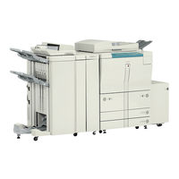
Canon iR7200 Series Service Manual (813 pages)
Brand:
Canon
| Category:
All in One Printer
| Size: 10.87 MB
Table of Contents
System Configuration
5
Cdrh Ordinances
8
Safety of Toner
13
Table of Contents
14
Error Code
24
Service Mode
24
Chapter 1 Introduction
25
Features
26
High-Speed, High-Quality Images
26
High Durability, High Reliability
26
High-Performance Controller, Large-Capacity Hard Disk for High-Level Processing
26
Ease of Use
26
Large Source of Paper
26
Various Delivery Handling (W/ Options)
27
High-Level Printing Functions Supporting Uses on a Network
27
Specifications
28
Copier
28
Chapter 2 New Function
28
Ir7200
28
Names of Parts
39
Using the Machine
47
Power Switch
47
Ir8500
47
Ir7200
48
Control Panel
49
Special Features
50
User Mode
51
New Functions
55
Stabilizing the Scanning Lamp
65
Detecting the State (Open/Closed) of the ADF
65
Detecting Dust in Stream Reading Mode
67
Disassembly/Assembly (Ir8500)
69
No. 1 Mirror Base Assembly
70
Scanner Drive Assembly
74
Pcbs
82
Others
88
Original Exposure System (Ir7200)
96
Outline
96
Arrangement of the Pcbs
99
Sequence of Operations (Original Exposure)
100
Book Mode, 1 Original, Copyboard Closed
100
Book Mode, 1 Original, Copyboard Cover Open
101
Enlargement/Reduction (Zoom)
102
Changing the Reproduction Ratio in Main Scanning Direction
102
Changing the Reproduction Ratio in Sub Scanning Direction
102
Scanner Drive System
103
Outline
103
Controlling the Scanner Motor
104
Controlling the Scanning Lamp (LA101)
106
Outline
106
Scanning Lamp
106
Turning On/Off the Lamp
106
Detecting an Error
107
Detecting the Size of Originals
108
Outline
108
Points of Detection
108
Outline of Detection
108
Disassembly/Assembly (Ir7200)
112
Removing the Reader Unit
113
Removing the Scanning Lamp
114
Points to Note When Replacing the Scanning Lamp
115
After Replacing the Scanning Lamp
116
Removing the Scanner Motor
116
Mounting the Scanner Motor
117
Removing the Scanner System Drive Cable
117
Routing the Scanner Drive Cable
120
Positioning the No. 1/2 Mirror Base
121
Removing the HP Sensor
123
Removing the Original Size Sensor
123
Removing the Copyboard Cover Sensor
124
Removing the Fuse PCB
125
Removing the Inverter
126
Outline of the Image Processing System (Ir8500)
128
Outline
128
4-Channels High-Speed CCD
130
CCD Adjustment
131
Analog Image Processing
132
Digital Image Processing
133
Detecting the Orientation of Originals
134
Disassembly/Assembly (Ir8500)
135
CCD Unit
136
Hard Disk
138
Image Processing System (Ir7200)
141
Outline
141
Analog Image Processing
142
Driving the CCD
142
Outline
142
A/D Conversion of the CCD Output
143
Gain Correction and Offset Correction of the CCD Output
143
Shading Correction
145
Auto Density Adjustment (AE)
146
Disassembly/Assembly (Ir7200)
149
CCD/Ap Pcb
150
Reader Controller PCB
151
Hard Disk
152
Laser Exposure System
155
Outline
155
Disassembly/Assembly
158
Reader Unit
159
Laser Unit
160
BD Unit
161
Image Formation System
163
Outline
163
Photosensitive Drum
166
Pre-Transfer Exposure LED (Addition)
166
Preventing Overheating of the Developing Unit
167
Development Fan
167
Revising the Developing Cylinder Cover
167
2-Speed Drive of the Developing Cylinder
169
Disassembly/Assembly
171
Process Unit
172
Charging Wires
177
Area Around the Process Unit
183
Pickup/Feeding System
186
Outline
186
System (Ir8500)
188
List of Changes Made to the Pickup/Feeding System (Ir7200)
188
Index Sheet Attachment
188
Disassembly/Assembly
189
Manual Feed Tray Assembly
190
Vertical Path Roller Assembly
194
Registration Feed Assembly
197
Duplexing Unit
198
Others
200
Fixing System
201
Outline
201
Controlling the Fixing Temperature
204
Transparency Mode
205
Thick Paper Mode
206
Power Save Mode
207
Error Detection
208
Down Sequence Control (100V)
209
Disassembly/Assembly
211
Fixing Heater and the Control Parts
212
Fixing Roller Assembly
218
Delivery Assembly
221
Paper Sensors
224
Externals/Auxiliary Controls
228
Changes Made to the Externals/Auxiliary Controls
228
Fans
229
Sequence of Operations (Fans)
231
Disassembly/Assembly
233
External Covers
234
Control Panel
246
Drive Assembly
260
Switches
264
Pcbs
266
Others
278
Main Power Switch
281
Side Paper Deck
282
Outline
282
Chapter 3 Main Controller
284
Basic Operation
285
Functional Construction
285
Outline of the Electrical Circuit
286
Hard Disk Drive
286
Main Controller PCB
286
Outline
286
Start-Up Sequence
288
Outline
288
Start-Up Sequence
289
Composition of the System Software
290
Inputs to and Outputs from the Major Pcbs
291
Wiring Diagram of the Major Pcbs
291
Digital Image Processing
292
Outline
292
Input Image Processing
293
Binary Processing (Error Diffusion Method; T-BIC)
293
Density Conversion (LUT)
293
Edge Emphasis
293
Editing
293
Enlargement/Reduction (Main Scanning Direction)
293
Image Data from the Reader Unit
293
Binary Processing (Dither Screen Method)
294
Controlling the Image Memory
294
Compression/Expansion, Rotation, and Enlargement/Reduction
294
Hdd
294
Sdram
294
Processing Output Image
294
Smoothing
294
Thickening (PDL Output Only)
294
Binary-Binary Density Conversion (Read Image Output Only)
295
Soft Counter
296
Controlling the Power Supply
298
Outline
298
Power Supply Mode
298
Standby Mode (Normal Operation)
298
Power Save Mode
298
Low-Power Mode
299
Shift from Standby Mode (Standby → Low-Power)
299
Shift to Standby Mode (Low-Power Mode → Standby)
299
Sleep Mode
299
Return to Standby Mode (Sleep → Standby)
299
Shift from Low Power Mode (Low-Power Mode → Sleep)
299
Shift from Standby Mode (Standby → Sleep)
299
Off Mode
300
Return to Standby Mode (off Mode → Standby)
300
Shift from Low-Power Mode (Low-Power → off Mode)
300
Shift from Standby Mode (Standby → off Mode)
300
Power Supply off Mode
300
Chapter 4 Installation
301
Selecting the Site
302
Unpacking and Installation (Ir8500 Series)
305
Points to Note before Starting the Installation Work
305
Attachments
306
Unpacking
307
Mounting the Scanner System (Ir8500/Ir8500P)
312
Mounting the Fixing Assembly
313
Mounting the Charging Assembly
315
Checking the Developing Assembly
320
Mounting the Pickup Assembly
322
Supplying the Toner
324
Installing the ADF (Ir8500/Ir8500P)
326
Cassette
327
Index Paper Attachment
328
Attaching the Labels, Setting Paper, Checking Images/Operations, and User Mode
329
Connecting to the Network
333
Checking the Connection to the Network
333
Troubleshooting Network Faults
334
Changing the Paper Size for the Front Deck (Right, Left)
335
Unpacking and Installation (Ir7200 Series)
337
Points to Note before Starting the Work
337
Attachments
338
Unpacking
339
Mounting the Scanner System (Ir8500/Ir8500P)
344
Mounting the Fixing Assembly
345
Mounting the Charging Assembly
347
Checking the Developing Assembly
352
Mounting the Pickup Assembly
354
Supplying the Toner
356
Connectors
358
Cassette
359
Index Paper Attachment
359
Setting Label Sheet/Paper, Checking Images and Operation, and Using User Mode
359
Connecting to the Network
359
Checking the Connection to the Network
359
Troubleshooting Network Faults
359
Switching the Paper Size for the Front Deck (Right, Left)
359
Relocating the Machine
360
Installing the Card Reader-D1
361
The Card Reader-D1
361
Installing the NE Controller-A1/NE Controller-B1/ Copy Data Controller-A1
366
Installing the NE Controller-A1
366
Controller-A1
366
Installing the Network LIPS Printer Kit -B1
370
Installing the Network LIPS
370
Chapter 5 Maintenance and Inspection
377
Periodically Replaced Parts
378
Guide to Durables
381
Copier
381
Side Paper Deck
385
Scheduled Servicing Work
386
Scheduled Service Chart
390
Chapter 6 Troubleshooting
403
Guide to the Troubleshooting Tables
404
Image Adjustment Basic Procedure
406
Making Pre-Checks
406
Making Checks on the Printer Side (1/2)
407
Making Checks on the Printer Side (2/2)
408
Making Checks on the Scanner Side (Ir8500)
409
Making Checks on the Reader Unit (Ir7200)
410
Standards and Adjustments
412
Making Image Adjustments
412
Adjusting the Image Position for Printer Output
412
Adjusting the Image Position for Copier Output (Book Mode)
417
Adjusting the Image Position for Copier Output (ADF Mode)
420
Scanner System
421
Adjusting the Position of the Scanner Mirror Base
421
Replacing the Scanner Drive Cable
421
The Standard White Plate
421
When Replacing the Scanning Lamp/When Replacing
421
Image Formation System
422
Assembly
422
Pickup/Feeding System
423
Orientation of the Deck/Cassette Pickup Roller
423
Orientation of the Deck/Cassette Separation Roller
424
Orientation of the Feeding Roller of the Deck/Cassette Pickup Assembly
424
Orientation of the Pickup Roller of the Manual Feed Tray/Side Paper Deck
425
Orientation for the Feeding Roller of the Manual Feed Tray
426
Orientation of the Feeding Roller of the Side Paper Deck
426
Adjusting the Pressure of the Separation Roller of the Deck/Cassette
427
Adjusting the Pressure of the Pickup/Feeding Roller of the Manual Feed Tray
428
Position of the Solenoids
429
Position of the Fixing Web Solenoid (SL2)
430
Position of the Delivery Flapper Solenoid (SL3)
432
Position of the Fixing Feeding Unit Locking Solenoid (SL4)
433
Adjusting the Position for the Multifeeder Pickup Latch Solenoid (SL6)
434
Position of the Deck (Right) Pickup Solenoid (SL7)
435
Position of the Deck (Left) Pickup Solenoid (SL8)
436
Pickup Solenoid (SL9/10)
437
Position of the Side Paper Deck Pickup Roller Releasing Solenoid
438
Attaching the Timing Belt for the Manual Feed Tray Assembly Side Guide
438
Attaching the Drive Belts
439
Fixing System
440
Points to Note When Mounting the Fixing Heater
440
Adjusting the Lower Roller Pressure (Nip Width)
441
Laser Exposure System
442
Replacing the Laser Unit
442
Checking the Laser Power
443
Items Related to Electrical Components
446
Electrical Components Requiring Work after Replacement
446
Points to Note When Replacing the CCD Unit
446
When Replacing the Reader Controller PCB (Ir8500)
448
When Replacing the Reder Controller PCB (Ir7200)
449
Replacing the HDD Unit
450
Replacing the Main Controller PCB
450
Replacing the DC Controller PCB
451
After Replacing the High-Voltage DC PCB
452
Replacing the Potential Sensor/Potential Control PCB
453
When Replacing the Laser Unit
453
Checking the Surface Potential Control System
457
Conversion Table for the Potential Control System
463
Checking the Environment Sensor
468
Checking the Photointerrupters
469
Troubleshooting Image Faults
475
Making Initial Checks
475
Checking the Originals against Symptoms
475
Site of Installation
475
Checking the Charging Wires
476
Checking the Copyboard Cover, Copyboard Glass, and Standard White Plate for Dirt and Scratches
476
Checking the Developing Assembly
476
Checking the Paper
476
Checking the Periodically Replaced Parts
476
Others
476
Sample Faulty Images
479
Troubleshooting Faulty Images
480
The Copy Is too Light (Halftone Area)
480
The Copy Is too Light (Entire Face, Considerable)
481
The Copy Is too Light (Solid Black Area)
481
The Copy Has Uneven Density (Darker Front)
483
The Copy Has Uneven Density (Lighter Front)
483
The Copy Is Foggy (Entire Face)
484
The Copy Has a Vertical Line (Vertical, Thick, Fuzzy)
485
The Copy Is Foggy in Vertical Direction
485
The Copy Has a Black Line (Vertical, Fine)
486
The Copy Has White Lines (Vertical)
487
The Copy Has White Spots (Vertical)
487
The Copy Has White Spots (Horizontal)
489
The Back of the Copy Is Soiled
490
The Copy Has Faulty Fixing
490
The Copy Has a Displaced Leading Edge (Considerably Large Margin)
491
The Copy Has a Displaced Leading Edge (Large Margin)
491
The Copy Has a Displaced Leading Edge (no Margin)
491
The Copy Is Wobbly
492
The Copy Has Poor Sharpness
493
The Copy Is Foggy Horizontally
493
The Copy Is Blank
494
The Copy Is Solid Black
495
Troubleshooting Malfunctions
496
Troubleshooting
496
Malfunctions
496
E000
496
E001
497
E002
498
E003
498
E004
499
E005
499
E010
499
E012
500
E013
500
E014
501
E015
501
E019
502
E020
503
E025
503
E032
504
E043
504
E051
505
E065
506
E067
507
E068
508
E069
509
E100
510
E110
510
E111
511
E121-0001
511
E121-0002
512
E202 (the Keys in the Control Panel Become Locked)
512
E204 (the Keys in the Control Panel Become Locked)
512
E211
513
E215
513
E218
513
(Indicated if Ir8500)
514
E219
514
E220 (Ir8500)
514
E222
514
E220 (Ir7200)
514
E225 (Ir7200)
514
E226 (Ir8500)
515
E240
515
E241 (Ir8500)
515
E243
516
E248 (Ir7200)
516
E251
516
E302
517
E315
517
E320
517
E400
517
E402
518
E404
519
E405
521
E410
522
E412
523
E420
523
E421
524
E422 (Ir8500)
524
E422 (Ir7200)
524
E601
525
E602
525
E676
526
E677
526
E710-0001 (Reader Controller PCB), E710-0002 (DC Controller PCB)
526
E710-0003 (Main Controller PCB)
526
E711-0001 (Reader Controller PCB), E711-0002 (DC Controller PCB)
526
E711-0003 (Main Controller PCB)
526
E712
527
E713
527
E717
528
E732
528
E733
529
E737
529
E740
529
E741
530
E744
530
E800
530
E804
531
E805
531
E820
532
E823
532
E824
533
E830
533
AC Power Is Absent
534
DC Power Is Absent
535
Pickup Fails
536
The Lifter Fails to Move up
538
The Lifter Fails to Move up (Pickup from Cassette)
539
Pickup Fails (Multifeeder)
540
The Vertical Path Roller Fails to Rotate
542
The Registration Roller Fails to Rotate
544
The No. 1 Mirror Base Fails to Operate
545
The Pre-Exposure Lamp Fails to Go on
546
The Scanning Lamp Fails to Go on
546
The Toner Feed Motor (M6) Inside the Cartridge Fails to Operate
547
The Toner Feed Motor (M18) Inside the Hopper Fails to Rotate
547
The Drum Heater Fails to Operate
548
The "Add Toner" Message Fails to Turn on
548
The "Add Toner" Message Fails to Go off
549
The "Card Reader Set" Message Fails to Go off
549
The "Card Reader Set" Message Fails to Turn on
549
The "Add Paper Message" Fails to Go off (Cassette 3/4)
550
The "Add Paper" Message Fails to Go off (Deck Right/Left)
550
The Fixing Heater Fails to Operate
551
Pickup Fails (Side Paper Deck)
552
The Deck Lifter Fails to Move up (Side Paper Deck)
553
Troubleshooting Feeding Faults
554
Paper Jams
554
Pickup Assembly
555
Separation/Feeding Assembly
556
Fixing/Delivery Assembly
557
Cleaning Assembly
558
Fixing, Delivery Assembly (Reversal Delivery Assembly)
558
Lower Feeding Assembly
559
Faulty Feeding
560
Double Feeding
560
Wrinkles
560
Arrangement and Function of Electrical Parts
561
Clutches
561
Solenoids
563
Motors
565
Fans
567
Sensor 1
569
Sensor 2
573
Switches
575
Counters, Heaters, Fuses, and Others
577
Pcbs
579
Variable Registers (VR), Light-Emitting Diodes, and Check Pins by PCB
583
Main Controller PCB
583
Reader Controller PCB (Ir7200)
584
Reader Controller PCB (Ir8500)
584
DC Controller PCB
585
Hv-DC Pcb
586
Upgrading
587
Outline
587
Download Mode
587
Making Pre-Checks
588
Data Control
591
Downloading the System Software, RUI, and Language Module
594
Downloading
594
Making Connections
594
After Downloading
600
Upgrading the BOOT ROM
600
Making Preparations
600
Connection
601
Preparing BOOT ROM
601
After Downloading
605
Formatting the HDD
606
Making Connections
606
Starting Formatting
606
Points to Note When Formatting the Hard Disk
612
Upgrading by Replacing the DIMM/ROM
613
Backing up Data
615
Outline
615
Backing up Data
616
Making Connections
616
Making Preparations
616
Backing up Data
617
Downloading Backup Data
622
Managing Backup Data
626
Appendix
629
General Timing Chart
630
List of Signals/Abbreviations
632
Service Mode
643
Construction of Service Mode
644
Outline
644
Starting Service Mode and Making Selections
645
Ending Service Mode
646
Backing up Service Mode
646
Basic Operation
647
Initial Screen
647
Level 3 Items Screen
647
Copier
649
I/O
666
Error Code
775
Error Codes
776
Advertisement
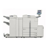
Canon iR7200 Series Function Manual (167 pages)
Remote UI Guide
Brand:
Canon
| Category:
Copier
| Size: 6.08 MB
Table of Contents
Manuals for the Machine
4
Table of Contents
7
Preface
9
How to Use this Manual
9
Symbols Used in this Manual
9
Keys and Buttons Used in this Manual
10
Displays Used in this Manual
11
Abbreviations Used in this Manual
12
Legal Notices
13
Trademarks
13
Copyright
13
Disclaimers
14
Chapter 1 Using the Remote UI
15
Machines Covered in this Manual
16
Overview of the Remote UI
17
System Requirements
23
Before You Start the Remote UI
24
Setting the Remote UI to on
25
Starting the Remote UI
29
Models Not Equipped with MEAP
29
Models Equipped with MEAP
30
Chapter 2 Remote UI Functions
35
Device Status and Information Display
36
Job Management
38
Managing Print Jobs
39
Managing Copy, Send, and Fax Jobs
45
Managing Receive Jobs
50
Managing the Ir3300/2800/2200 Fax Send and Receive Jobs
54
Managing Inboxes
60
User Inboxes
62
Printing the Document
65
Memory RX Inbox
77
Confidential Fax Inboxes
82
Printing PDF or PS Files Directly (Direct Print)
87
Printing PDF Files Directly
88
Printing PS Files Directly
92
Managing the Address Book
94
Managing the Ir Address Book
95
Operating the Address Book
96
Operating the System Reference Address
106
Managing the Ir3300/2800/2200 Address Book
109
Customizing System Settings
115
Customizing System Information
115
Restarting the Machine
120
Specifying LDAP Server Settings
124
Specifying Forwarding Settings
128
Managing Department Ids
135
Import/Export Function
141
Saving Ir Address Lists in Files
142
Loading an Address Book
145
Saving Forwarding Settings in Files (Export)
148
Loading a Forwarding Settings File (Overwrite/Import)
150
Saving Additional Functions Settings in Files (Export)
152
Loading Additional Functions Settings Files (Overwrite/Import)
154
Saving an Ir3300/2800/2200 Address Book as a File (Export)
156
Loading an Ir3300/2800/2200 Address Book from a File
158
(Overwrite/Import)
158
Loading an Ir3300/2800/2200 Address Book from a File (Overwrite/Import)
158
Device Custom Settings
160
Chapter 3 Appendix
163
Index
164
Advertisement
Related Products
Canon iR2030
Canon iR2010 Series
Canon iR1200 Series
Canon iR5020i
Canon iR2318 series
Canon iR5570N
Canon Color iR C2550i
Canon iR1024J
Canon iR2420 series
Canon iR5020N
Canon Categories
Printer
Digital Camera
All in One Printer
Camcorder
Scanner
More Canon Manuals
Login
Sign In
OR
Sign in with Facebook
Sign in with Google
Upload manual
Upload from disk
Upload from URL