Sign In
Upload
Manuals
Brands
Canon Manuals
Copier
Image Reader-A1
Canon Image Reader-A1 Manuals
Manuals and User Guides for Canon Image Reader-A1. We have
2
Canon Image Reader-A1 manuals available for free PDF download: Service Manual
Canon Image Reader-A1 Service Manual (916 pages)
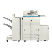
Photocopy Machines
Brand:
Canon
| Category:
Printer
| Size: 9.56 MB
Table of Contents
Table of Contents
11
Symbols Used
3
System Configuration
7
Chapter 1 General Description
15
Features
17
Addition of the Differential PCB
17
Hard Disk
17
High Speed, High Image Quality
17
Large-Capacity Paper Source
17
Printer Type
17
Stackless, Duplexing Mechanism
17
Variety of Delivery Processing (with Accessories)
17
Specifications
18
Copier
18
Method
18
Type
18
Functions
19
Others
24
Paper Deck-G1
27
Shift Tray-B1
28
Names of Parts
29
Using the Machine
35
Control Panel
42
Main Controller
42
Outline of Electrical Circuitry . 1-27S
43
Inputs to and Outputs from the Major Pcbs
44
Wiring Diagram of the Major Pcbs
44
Routine Maintenance by the User . 1-29S
45
Cleaning
45
Inspection
48
Making a Check
48
Wiring Diagram of the Major Pcbs
57
Digital Image Processing
58
Outline
58
Binary Processing (Error Diffusion; T-BIC)
59
Density Conversion (LUT) 2-9S
59
Edge Emphasis
59
Editing
59
Enlargement/Reduction (Main Scanning Direction)
59
Image Data from the Reader Unit
59
Input Image Processing
59
Binary Processing (Dither Screen)
60
Binary-Binary Density Conversion (Read Image Output Only)
61
Compression/Decompression, Rotation, Enlargement/Reduction
61
Controlling the Image Memory
61
Hard Disk Drive (HDD)
61
Output Image Processing
61
Sdram
61
Smoothing
61
Thickening (PDL Output Only)
61
Flow of Image Data
62
Flow of Image Data During Copying
62
Local Copying
62
Remote Copying
63
Tandem Copying
64
Outline
65
Transmission
65
Flow of Image Data (During Transmission)
66
Flow of Print Jobs
67
Print
67
Tcp/Ip
68
Netware
69
Appletalk
70
Processing Print Data
71
Soft Counter
72
Controlling the Power Supply
74
Outline
74
Power Supply Mode
74
Standby Mode (Normal Operation)
74
Power Save Mode
74
Low Power Mode
75
Shift from Standby Mode (Standby → Low-Power)
75
Shift to Standby Mode (Low Power → Standby)
75
Sleep Mode
75
Return to Standby Mode (Sleep → Standby)
75
Shift from Low Power Mode (Low Power Mode → Sleep)
75
Shift from Standby Mode (Standby → Sleep)
75
Off Mode
76
Return to Standby Mode (off Mode → Standby)
76
Shift from Low Power Mode (Low Power Mode → off Mode)
76
Shift from Standby Mode (Standby → off Mode)
76
Power off Mode
76
User Software
77
Outline
77
Printer Drivers
77
Utilities
77
JBIG Viewer
77
Netspot
77
Network Scangear(Windows Only)
77
Selecting the Site
81
Unpacking and Installation
83
Before Starting the Work
83
Installation
84
Unpacking
85
Installing the Image Reader-A1
87
Mounting the Fixing Assembly
92
Checking the Charging Assemblies
94
Mounting the Developing Assembly
97
Mounting the Pickup Assembly
98
Mounting the Deck Locking Plate (Left Deck)
99
Supplying Toner
100
Setting the Cassette
101
Changing the Paper Size for the Front Deck (Right/Left)
102
Installing the DADF-D1
102
Checking Images/Operations and User Mode
103
Turning on the Power
103
Checking the Environment Switch
105
Connecting to the Network
106
Installing the Machine
106
Checking the Connection to the Network
107
Troubleshooting the Network
108
Relocating the Machine
109
Mounting the Delivery Tray
110
Mounting the Original Holder
112
Installing the Card Reader-C1 (Option)
113
Installing the NE Controller-A1
114
Installation
114
Table of Contents
119
Chapter 1 Basic Operation
121
Functional Construction
123
Outline of Electrical Circuitry
124
Outline
124
Reader Controller PCB
124
Basic Sequence of Operations
125
Basic Sequence of Operations at Power-On
125
Chapter 2 Original Exposure System
129
Outline of Operations
131
Outline
131
Book Mode, 1 Original, Copyboard Closed
133
Sequence of Operations (Original Exposure)
133
Copyboard Cover Open
134
Changing the Reproduction Ratio in Main Scanning Direction
135
Changing the Reproduction Ratio in Sub Scanning Direction
135
Enlargement/Reduction (Zoom)
135
Scanner Drive System
136
Outline
136
Controlling the Motor When Scanning an Image
137
Controlling the Scanner Motor
137
Reversing the Scanner after Scanning in Main Reading Direction
138
Controlling the Scanning Lamp (LA2)
139
Outline
139
Turning On/Off the Lamp
139
Detecting an Error
140
Detecting the Size of Originals
141
Outline
141
Outline of Detection
141
Points of Detection
141
Book Mode, 1 Original, Copyboard Cover Open
142
Outline of Detection Operation
142
Scanning Lamp
145
Removing the Scanning Lamp
145
After Replacing the Scanning Lamp
147
Points to Note When Replacing the Scanning Lamp
147
Scanner Drive Block
148
Removing the Scanner Motor
148
Scanner Motor
148
Mounting the Scanner Motor
149
Removing the Scanner System Drive Cable
150
Scanner System Drive Cable
150
Routing the Scanner Drive Cable
152
Positioning the No. 1/2 Mirror Base
153
Others
155
Removing the Hp Sensor
156
Chapter 3 Image Processing System
161
Outline
163
Analog Image Processing
164
Driving the CCD
164
Outline
164
A/D Conversion of the CCD Output
165
Gain Correction and Offset Correction of the CCD Output
165
Digital Image Processing
166
Outline
166
Shading Correction
166
Shading Adjustment
167
Shading Correction
167
Edge Gain Correction (ADF in Use)
168
ABC Circuit
169
Auto Density Adjustment (AE)
169
Outline
169
External Covers
171
Removing the Reader Left Cover
171
Removing the Reader Right Cover
171
Removing the Rear
172
Removing the Reader Rear Cover
173
CCD/Ap Pcb
174
Removing the CCD Unit
174
When Replacing the CCD/AP PCB
175
Reader Controller PCB
176
Removing the Reader Controller PCB
176
When Replacing the Reader Controller PCB
176
Removing the Differential PCB
177
Table of Contents
181
Chapter 1 General Description
191
Safety
193
Regulations under the Center for Devices and Radiological Health
193
Safety of Laser Light
193
Handling the Laser Unit
195
Safety of Toner
198
Image Formation
199
Chapter 2 Sequence of Operations
201
Basic Operations
203
Functional Construction
203
DC Controller PCB
204
Outline
204
Outline of Electrical Circuitry
204
Basic Sequence of Operations at Power-On
206
Sequence of Basic Operations
206
Controlling the Main Motor (M2)
208
Wiring Diagram of Major Pcbs
209
Chapter 3 Laser Exposure System
225
Outline of Operations
227
Outline
227
Basic Sequence of Operations (Laser Exposure System)
229
Generating Sync Signals
230
Outline
230
Flow of Sync Signals
231
Controlling the Laser Scanner Motor
235
Disassembly and Assembly
236
Scanner Unit
237
Chapter 4 Image Formation System
239
Outline of Processes
241
Outline
241
Basic Sequence of Operations (Image Formation System)
243
Potential Control
245
Outline
245
Controlling Potential for Printing/Copying
246
Determining Primary Current
251
Determining the Laser Output
252
Determining the Developing Bias
253
APC Correction
254
Density Adjustment During Copying
256
Density Adjustment in each Mode
256
Density Adjustment During Printing
257
Controlling Charging
258
Controlling Pre-Exposure LED
258
Outline
258
Controlling Primary Charging
259
Outline
259
Primary Charging Assembly Cleaning Mechanism
260
Others
261
Dust-Collecting Roller Bias
262
Controlling the Output to Suit the Environment (Fuzzy Control)
263
Controlling the Pre-Transfer Charging
263
Outline
263
Cleaning Mechanism for the Pre-Transfer Charging Assembly
265
Others
266
Controlling the Output to Suit the Environment (Fuzzy Control)
267
Controlling Transfer Charging
267
Outline
267
Cleaning Mechanism for the Transfer Charging Assembly
269
Others
270
Controlling Separation Charging
272
Outline
272
Correcting the Output to Suit the Environment and the Density of the Original Used
274
Others
275
Hopper/Developing Assembly
276
Outline
276
Controlling the Drive to the Hopper/Developing Assembly
277
Controlling the Developing Bias
279
Detecting the Level of Toner and Controlling the Supply of Toner
281
Sequence of Operations (Toner Supply)
282
Drum Cleaner Unit
283
Outline
283
Detecting the Waste Toner
284
Controlling the Drum Heater
286
Outline
286
Disassembly and Assembly
289
Pre-Exposure Lamp Unit
290
Removing the Pre-Exposure Lamp Unit
290
Photosensitive Drum
291
Removing the Drum Unit
291
Replacing the Drum Heater
292
Mounting the Photosensitive Drum
293
Setting the DIP Switch for the Drum Heater Control PCB
293
Process Unit
294
Removing the Process Unit
294
Mounting the Process Unit
296
Potential Sensor/Potential Control PCB
297
Removing the Potential Sensor/Potential Control PCB
297
Adjusting the Potential Sensor
299
Primary Charging Assembly
301
Removing the Primary Charging Assembly
301
Pre-Transfer Charging Assembly
302
Removing the Pre-Transfer Charging Assembly
302
Transfer/Separation Charging Assembly
303
Removing the Transfer/Separation Charging Assembly
303
Mounting the Transfer/Separation Charging Assembly
304
Charging Wire
306
Outline
306
Removing the Wire Cleaner of the Primary Charging Assembly
306
Routing the Charging Wire
306
Routing the Grid for the Primary Charging Assembly
309
Adjusting the Height of the Charging Wire
311
Cleaning the Primary Anti-Stray Sheet
312
Developing Assembly
313
Removing the Developing Assembly from the Machine
313
Removing the Blade Unit
314
Mounting the Blade
315
Removing the Developing Cylinder/Magnetic Seal
315
Cleaning the Developing Anti-Stray Sheet
317
Hopper Assembly
318
Removing the Hopper Assembly from the Machine
318
Drum Cleaner
319
Construction
319
Removing the Cleaning Blade
319
Mounting the Cleaning Blade
320
Mounting the Side Seal
322
Cleaning the Cleaner Side Scraper
323
Separation Claw/Separation Claw Drive Assembly
324
Removing from the Drum Unit
324
Chapter 5 Pick-Up/Feeding System
325
Outline
327
Specifications and Construction
327
Arrangement of Roller and Sensors
328
Pickup Assembly
330
Pickup Control System
330
Outline
332
Sequence of Operations (Pickup)
333
Pickup Retry Operation
335
Lifter Movement
337
Outline
337
Lifter Limiter Control Circuit (Right/Left Deck)
339
Detecting the Level of Paper
340
Detecting the Presence/Absence of Paper
340
Cassette 3/4
343
Identifying the Size of Paper in the Cassette
343
Right/Left Deck
343
Markings on the Width Guide Rail
345
Paper Sizes
346
Manual Feed Tray Pickup Assembly
349
Pickup Operation
349
Detecting the Size of Paper on the Manual Feed Tray
350
Controlling the Registration Clutch
351
Control System
351
Outline
351
Double-Sided Prints
352
Control System
352
Sending Paper to the Reversing Assembly after Printing on the First Side
352
Sending Paper from the Revers- Ing Assembly to the Duplexing/Feeding Assembly
353
Outline
354
Sequence of Operations (Printing)
355
Outline
356
Through-Path Operation
356
Outline of Operations
357
Detecting Horizontal Registration Position
361
Outline
361
Operation
362
Controlling the Pickup Assembly . 5-37P
363
Pickup Assembly Motors
363
Controlling the Delivery Assembly
364
Reversal Delivery Operation
364
Controlling the Cassette Heater
366
Detecting Jams
368
Arrangement of Jam Sensors
368
Outline
368
Types of Jams
369
Delay Jam
370
Sequence of Operations (Jam Detection)
370
Stationary Jams
372
Jam History
373
Disassembly and Assembly
374
Manual Feed Tray Assembly
375
Opening of the Right Upper Cover
375
Removing the Right Upper Cover
375
Removing the Feeding Roller
376
Removing the Manual Feed Pull-Out Roller Unit
376
Removing the Separation Roller
376
Adjusting the Pressure of the Separation Roller
377
Removing the Manual Feed Tray Paper Sensor
378
Attaching the Side Guide Timing Belt in the Manual Feed Tray Assembly
379
Removing the Manual Feed Pull-Out Roller
379
Deck Pickup Assembly
380
Removing the Left Deck Pickup Assembly
380
Removing the Right Deck Pickup Assembly
380
Removing the Cassette 3 Pickup Assembly
381
Removing the Cassette 4 Pickup Assembly
381
Removing the Pickup Roller
381
Removing the Feeding Roller
382
Orientation of the Feeding Roller of the Deck/Cassette Pickup Assembly
383
Removing the Separation Roller
383
Adjusting the Separation Roller Pressure
385
Orientation of the Separation Roller
385
Adjusting the Left/Right Registration for the Front Deck
386
Adjusting the Registration for the Cassette 3/4
386
Adjusting the Position of the Lifter Motor M20 (M21) of the Cassette 3 (Cassette 4)
387
Removing the Lifter Motor M20 (M21) of the Cassette 3 (4)
387
Adjusting the Position of the Cassette 3/4 Pickup Solenoid (SL3, 4)
389
Vertical Path Roller Assembly
390
Removing the Vertical Path Roller 1
390
Removing the Vertical Path Roller 2
390
Removing the Vertical Path Roller 3/4
390
Registration Feeding Assembly
392
Removing the Registration Clutch
392
Removing the Registration Roller
392
Feeding Assembly
394
Removing the Feeding Belt
394
Removing the Fixing/Feeding Unit Releasing Lever Switch
395
Duplex Unit
396
Removing the Duplex Unit
396
Removing the Reversal Motor
396
Removing the Reversing Flapper Solenoid
396
Mounting the Reversal Motor
397
Removing the Duplex Feeding Right Motor
398
Removing the Duplexing Feeding Left Motor
398
Removing the Duplex Pre-Registration Sensor
399
Removing the Horizontal Registration Motor
399
Removing the Duplex Paper Sensor
400
Removing the Reversal
401
Removing the Left Deck Feed Paper Sensor
402
Removing the Duplex Driver PCB
403
Removing the Horizontal Registration Sensor
403
Chapter 6 Fixing System
407
Outline of Operation
409
Outline
409
Basic Sequence of Operations (Fixing System)
412
Fixing Drive System
413
Outline
413
Controlling the Drive of the Fixing Roller
414
Controlling the Drive of the Cleaning Web
415
Controlling the Drive of the Fixing Assembly Inlet Guide
416
Controlling the Reciprocating Mechanisms of the Thermistor
417
Controlling the Reciprocating Mechanism of the Upper Separation Claw
418
Controlling the Fixing Temperature
419
Outline
419
Temperature Control
420
Normal Sequence
421
During Printing
422
Temperature Control by Mode
423
Detecting Errors
426
Disassembly and Assembly
428
Fixing Assembly
429
Removing the Fixing/Feeding Unit
429
Removing the Fixing Assembly
430
Fixing Roller Cleaning Assembly
432
Removing the Fixing Web
432
Mounting the Fixing Web
433
Adjusting the Fixing Web Solenoid (SL9)
434
Fixing Heater and the Control Parts
435
Removing the Main/Sub Heater
435
Mounting the Main/Sub Heater
436
Removing the Thermal Switch
436
Removing the Main Thermistor
437
Removing the Sub Thermistor
439
Fixing Roller Assembly
440
Removing the Fixing Upper Roller
440
Mounting the Fixing Upper Roller
441
Removing the Fixing Lower Roller
441
Adjusting the Nip
442
Fixing Separation Assembly
443
Removing the Lower Separation Claw
443
Removing the Upper Separation Claw
443
Delivery Assembly
444
Removing the External Delivery Roller
444
Removing the Internal Delivery Roller
445
Adjusting the Position of the Delivery Flapper Solenoid (SL5)
446
Paper Sensor
447
Removing the Claw Jam Sensor
447
Chapter 7 Externals and Controls
451
Control Panel
453
Outline
453
Fans
454
Arrangement, Functions, and
454
Controlling the Speed
456
Operation
456
Sequence of Operations
456
Power Supply
457
Outline
457
Distribution of Power Among Switches
458
Output of Power Supplies
460
Rated Outputs of the DC Power Supply
461
Protection Mechanism
462
Others
464
Silent Mode
464
Disassembly and Assembly
465
External Covers
466
Removing the
467
Removing the Top Plate
467
Arrangement of Electrical Parts (Rear of the Machine)
468
Control Panel
470
Removing the Control Panel
470
Removing the LCD Panel
471
Removing the Control Panel Inverter PCB
472
Removing the Control Panel Family PCB
473
Pcbs
474
DC Controller PCB
474
Removing the Main Controller Box
475
Removing the Ethernet PCB
478
Removing the Main Controller PCB
478
Remove the Differential PCB
479
Removing the LIPS PCB
479
Removing the RISER PCB
480
Power Supply PCB
481
High-Voltage Power Supply PCB
482
AC Driver PCB
483
Accessories Power Supply PCB
483
Anti-Rush Current PCB
484
Motor Driver PCB
484
Serial Number PCB
485
Fans
486
Exhaust Fan
486
Feeding Fan
486
DC Power Supply Fan
487
HDD Fan
487
Primary Charging Cooling Fan
488
Drive System
489
Left Deck Drive Assembly
489
Vertical Path Duplex/Right Deck Drive Assembly
489
Main Motor Drive Assembly
490
Manual Feed Pickup Drive Assembly
490
Drum Drive Assembly
491
Left Deck Pull-Out Roller Drive Assembly
491
Waste Toner Drive Assembly
491
Drive Assembly
492
Left Deck Lifter Drive Assembly
494
Motor
495
Main Motor (M2)
495
Vertical Path Lower
495
Pickup Motor (M12)
496
Vertical Path Duplex Motor
496
Pre-Registration Motor (M17) and Drum Motor (M1)
497
Solenoid
499
Adjusting the Position of the Right Deck Pickup Solenoid (SL6)
499
Right Deck Pickup Roller Releasing Solenoid (SL6)
499
Adjusting the Position of the Left Deck Pickup Solenoid (SL7)
500
Right Deck Pickup Roller Releasing Solenoid (SL7)
500
Clutches
501
Manual Feed Pickup Clutch
501
Sensors
502
(Width/Length) Sensor
502
Cassette 3/4 Paper Size
502
Hdd
503
Others
506
DC Controller PCB
506
Relay
506
Power Supply
507
Transformer
507
Inputs to the Driver (1/2)
511
Outputs from the Deck Driver (2/2)
512
Removing the Rear Cover
533
Removing the Upper Cover
534
General Descriptions
535
Troubleshooting
569
Chapter 8 Paper Deck
511
Advertisement
Canon Image Reader-A1 Service Manual (878 pages)
Brand:
Canon
| Category:
Copier
| Size: 10.02 MB
Table of Contents
System Unit
10
System Configuration
7
Table of Contents
10
Chapter 1 General Description
13
Features
14
Addition of the Differential PCB
14
Hard Disk
14
High Speed, High Image Quality
14
Large-Capacity Paper Source
14
Printer Type
14
Stackless, Duplexing Mechanism
14
Variety of Delivery Processing (with Accessories)
14
Specifications
15
Copier
15
Method
15
Type
15
Functions
16
Others
21
Paper Deck-G1
24
Shift Tray-B1
25
Names of Parts
26
External View
26
Using the Machine
32
User Mode
35
Control Panel
39
Hard Disk Drive
39
Main Controller PCB
39
System Construction
39
Outline of Electrical Circuitry 1-27S
40
Inputs to and Outputs from the Major Pcbs
41
Wiring Diagram of the Major Pcbs
41
Routine Maintenance by the User 1-29S
42
Cleaning
42
Inspection
45
Making a Check
45
Wiring Diagram of the Major Pcbs
53
Digital Image Processing
54
Outline
54
Binary Processing (Error Diffusion; T-BIC)
55
Density Conversion (LUT) 2-9S
55
Edge Emphasis
55
Editing
55
Enlargement/Reduction
55
Image Data from the Reader Unit
55
Input Image Processing
55
Binary Processing (Dither Screen)
56
Binary-Binary Density Conversion (Read Image Output Only)
57
Compression/Decompression, Rotation, Enlargement/Reduction
57
Controlling the Image Memory
57
Hard Disk Drive (HDD)
57
Output Image Processing
57
Sdram
57
Smoothing
57
Thickening (PDL Output Only)
57
Flow of Image Data
58
Flow of Image Data During Copying
58
Local Copying
58
Remote Copying
59
Tandem Copying
60
Outline
61
Transmission
61
Flow of Image Data (During Transmission)
62
Image Processor Pcb
62
Flow of Print Jobs
63
Print
63
Tcp/Ip
64
Netware
65
Appletalk
66
Processing Print Data
67
Soft Counter
68
Controlling the Power Supply
70
Outline
70
Power Supply Mode
70
Standby Mode (Normal Operation)
70
Power Save Mode
70
Low Power Mode
71
Shift from Standby Mode (Standby → Low-Power)
71
Shift to Standby Mode (Low Power → Standby)
71
Sleep Mode
71
Return to Standby Mode (Sleep → Standby)
71
Shift from Low Power Mode (Low Power Mode → Sleep)
71
Shift from Standby Mode (Standby → Sleep)
71
Off Mode
72
Return to Standby Mode (off Mode → Standby)
72
Shift from Low Power Mode (Low Power Mode → off Mode)
72
Shift from Standby Mode (Standby → off Mode)
72
Power off Mode
72
User Software
73
Outline
73
Printer Drivers
73
Utilities
73
JBIG Viewer
73
Netspot
73
Network Scangear(Windows Only)
73
Selecting the Site
75
Unpacking and Installation
77
Before Starting the Work
77
Installation
78
Unpacking
79
Installing the Image Reader-A1
81
Mounting the Fixing Assembly
86
Checking the Charging Assemblies
88
Mounting the Developing Assembly
91
Mounting the Pickup Assembly
92
Mounting the Deck Locking Plate (Left Deck)
93
Supplying Toner
94
Setting the Cassette
95
Changing the Paper Size for the Front Deck (Right/Left)
96
Installing the DADF-D1
96
Checking Images/Operations and User Mode
97
Checking the Environment Switch
99
Connecting to the Network
100
Installing the Machine
100
Checking the Connection to the Network
101
Troubleshooting the Network
102
Relocating the Machine
103
Mounting the Delivery Tray
104
Mounting the Original Holder
106
Installing the Card Reader-C1 (Option)
107
Installing the NE Controller-A1
108
Installation
108
Reader Unit
111
Chapter 1 Basic Operation
113
Functional Construction
114
Outline of Electrical Circuitry
115
Outline
115
Reader Controller PCB
115
Basic Sequence of Operations
116
Basic Sequence of Operations at Power-On
116
Chapter 2 Original Exposure System
120
Outline of Operations
121
Outline
121
Book Mode, 1 Original, Copyboard Closed
123
Sequence of Operations (Original Exposure)
123
Copyboard Cover Open
124
Changing the Reproduction Ratio in Main Scanning Direction
125
Changing the Reproduction Ratio in Sub Scanning Direction
125
Enlargement/Reduction (Zoom)
125
Scanner Drive System
126
Outline
126
Controlling the Motor When Scanning an Image
127
Controlling the Scanner Motor
127
Reversing the Scanner after Scanning in Main Reading Direction
128
Controlling the Scanning Lamp (LA2)
129
Outline
129
Pcbs
129
Turning On/Off the Lamp
129
Detecting an Error
130
Detecting the Size of Originals
131
Outline
131
Outline of Detection
131
Points of Detection
131
Book Mode, 1 Original, Copyboard Cover Open
132
Outline of Detection Operation
132
Scanning Lamp
135
Removing the Scanning Lamp
135
After Replacing the Scanning Lamp
137
Points to Note When Replacing the Scanning Lamp
137
Scanner Drive Block
138
Removing the Scanner Motor
138
Scanner Motor
138
Mounting the Scanner Motor
139
Removing the Scanner System Drive Cable
140
Scanner System Drive Cable
140
Routing the Scanner Drive Cable
142
Positioning the No. 1/2 Mirror Base
143
Others
145
Removing the Original Size Sensor
145
Removing the Copyboard Sensor
147
Removing the Fuse Pcb
148
Removing the Inverter Pcb
149
Chapter 3 Image Processing System
151
Outline
152
Analog Image Processing
153
Driving the CCD
153
Outline
153
A/D Conversion of the CCD Output
154
Gain Correction and Offset Correction of the CCD Output
154
Digital Image Processing
155
Outline
155
Shading Correction
155
Shading Adjustment
156
Shading Correction
156
Edge Gain Correction (ADF in Use)
157
Auto Density Adjustment (AE)
158
Outline
158
External Covers
160
Removing the Reader Left Cover
160
Removing the Reader Right Cover
160
Removing the Rear
161
Removing the Reader Rear Cover
162
CCD/Ap Pcb
163
Removing the CCD Unit
163
When Replacing the CCD/AP PCB
164
Reader Controller PCB
165
Removing the Reader Controller PCB
165
When Replacing the Reader Controller PCB
165
Removing the Differential PCB
166
Printer Unit
168
Chapter 1 General Description
178
Safety
179
Regulations under the Center for Devices and Radiological Health
179
Safety of Laser Light
179
Handling the Laser Unit
181
Safety of Toner
184
Chapter 2 Sequence of Operations
187
Basic Operations
188
Functional Construction
188
DC Controller PCB
189
Outline
189
Outline of Electrical Circuitry
189
Basic Sequence of Operations at Power-On
191
Sequence of Basic Operations
191
Controlling the Main Motor (M2)
193
Wiring Diagram of Major Pcbs
194
Inputs to the DC Controller Pcb
195
Chapter 3 Laser Exposure System
209
Outline of Operations
210
Outline
210
Basic Sequence of Operations (Laser Exposure System)
212
Generating Sync Signals
213
Outline
213
Flow of Sync Signals
214
Controlling the Laser
215
Controlling the Laser Scanner Motor
218
Disassembly and Assembly
219
Scanner Unit
220
Chapter 4 Image Formation System
222
Outline of Processes
223
Outline
223
Basic Sequence of Operations (Image Formation System)
225
Potential Control
227
Outline
227
Controlling Potential for Printing/Copying
228
Determining Primary Current
233
Determining the Laser Output
234
Determining the Developing Bias
235
APC Correction
236
Density Adjustment During Copying
238
Density Adjustment in each Mode
238
Density Adjustment During Printing
239
Controlling Charging
240
Controlling Pre-Exposure LED
240
Outline
240
Controlling Primary Charging
241
Outline
241
Primary Charging Assembly Cleaning Mechanism
242
Others
243
Dust-Collecting Roller Bias
244
Controlling the Output to Suit the Environment (Fuzzy Control)
245
Controlling the Pre-Transfer Charging
245
Outline
245
Cleaning Mechanism for the Pre-Transfer Charging Assembly
247
Others
248
Controlling the Output to Suit the Environment (Fuzzy Control)
249
Controlling Transfer Charging
249
Outline
249
Cleaning Mechanism for the Transfer Charging Assembly
251
Others
252
Controlling Separation Charging
254
Outline
254
Correcting the Output to Suit the Environment and the Density of the Original Used
256
Others
257
Hopper/Developing Assembly
258
Outline
258
Controlling the Drive to the Hopper/Developing Assembly
259
Controlling the Developing Bias
261
Detecting the Level of Toner and Controlling the Supply of Toner
263
Sequence of Operations (Toner Supply)
264
Drum Cleaner Unit
265
Outline
265
Detecting the Waste Toner
266
Controlling the Drum Heater
268
Outline
268
Disassembly and Assembly
271
Pre-Exposure Lamp Unit
272
Removing the Pre-Exposure Lamp Unit
272
Photosensitive Drum
273
Removing the Drum Unit
273
Replacing the Drum Heater
274
4-52P
275
Mounting the Photosensitive Drum
275
Setting the DIP Switch for the Drum Heater Control PCB
275
Process Unit
276
Removing the Process Unit
276
Mounting the Process Unit
278
Potential Sensor/Potential Control PCB
279
Removing the Potential Sensor/Potential Control PCB
279
Adjusting the Potential Sensor
281
Primary Charging Assembly
283
Removing the Primary Charging Assembly
283
Pre-Transfer Charging Assembly
284
Removing the Pre-Transfer Charging Assembly
284
Transfer/Separation Charging Assembly
285
Removing the Transfer/Separation Charging Assembly
285
Mounting the Transfer/Separation Charging Assembly
286
Charging Wire
288
Outline
288
Removing the Wire Cleaner of the Primary Charging Assembly
288
Routing the Charging Wire
288
Routing the Grid for the Primary Charging Assembly
291
Adjusting the Height of the Charging Wire
293
Cleaning the Primary Anti-Stray Sheet
294
Developing Assembly
295
Removing the Developing Assembly from the Machine
295
Removing the Blade Unit
296
Mounting the Blade
297
Removing the Developing Cylinder/Magnetic Seal
297
Cleaning the Developing Anti-Stray Sheet
299
Hopper Assembly
300
Removing the Hopper Assembly from the Machine
300
Drum Cleaner
301
Construction
301
Removing the Cleaning Blade
301
Mounting the Cleaning Blade
302
Mounting the Side Seal
304
Cleaning the Cleaner Side Scraper
305
Separation Claw/Separation Claw Drive Assembly
306
Removing from the Drum Unit
306
Chapter 5 Pick-Up/Feeding System
307
Outline
308
Specifications and Construction
308
Arrangement of Roller and Sensors
309
Pickup Assembly
311
Pickup Control System
311
Outline
313
Sequence of Operations (Pickup)
314
Pickup Retry Operation
316
Lifter Movement
318
Outline
318
Lifter Limiter Control Circuit (Right/Left Deck)
320
Detecting the Level of Paper
321
Detecting the Presence/Absence of Paper
321
Cassette 3/4
324
Identifying the Size of Paper in the Cassette
324
Right/Left Deck
324
Markings on the Width Guide Rail
326
Paper Sizes
327
Manual Feed Tray Pickup Assembly
330
Pickup Operation
330
Detecting the Size of Paper on the Manual Feed Tray
331
Controlling the Registration Clutch
332
Control System
332
Outline
332
Double-Sided Prints
333
Control System
333
Sending Paper to the Reversing Assembly after Printing on the First Side
333
Sending Paper from the Revers- Ing Assembly to the Duplexing/Feeding Assembly
334
Outline
335
Sequence of Operations (Printing)
336
Outline
337
Through-Path Operation
337
Outline of Operations
338
Detecting Horizontal Registration Position
342
Outline
342
Operation
343
Controlling the Pickup Assembly 5-37P
344
Pickup Assembly Motors
344
Controlling the Delivery Assembly
345
Reversal Delivery Operation
345
Controlling the Cassette Heater
347
Detecting Jams
349
Types of Jams
350
Delay Jam
351
Sequence of Operations (Jam Detection)
351
Stationary Jams
353
Jam History
354
Disassembly and Assembly
355
Manual Feed Tray Assembly
356
Opening of the Right Upper Cover
356
Removing the Right Upper Cover
356
Removing the Feeding Roller
357
Removing the Manual Feed Pull-Out Roller Unit
357
Removing the Separation Roller
357
Adjusting the Pressure of the Separation Roller
358
Removing the Manual Feed Tray Paper Sensor
359
Attaching the Side Guide Timing Belt in the Manual Feed Tray Assembly
360
Removing the Manual Feed Pull-Out Roller
360
Deck Pickup Assembly
361
Removing the Left Deck Pickup Assembly
361
Removing the Right Deck Pickup Assembly
361
Removing the Cassette 3 Pickup Assembly
362
Removing the Cassette 4 Pickup Assembly
362
Removing the Pickup Roller 9.5.1
362
Orientation of the Feeding Roller of the Deck/Cassette Pickup Assembly
364
Adjusting the Separation Roller Pressure
366
Orientation of the Separation Roller
366
Adjusting the Left/Right Regis- Tration for the Front Deck 9.6.5
367
Adjusting the Registration for the Cassette 3/4
367
Adjusting the Position of the Lifter Motor M20 (M21) of the Cassette 3 (Cassette 4)
368
Removing the Lifter Motor M20 (M21) of the Cassette 3 (4)
368
Adjusting the Position of the Cassette 3/4 Pickup Solenoid (SL3, 4)
370
Vertical Path Roller Assembly
371
Removing the Vertical Path Roller 1
371
Removing the Vertical Path Roller 2
371
Removing the Vertical Path Roller 3/4
371
Registration Feeding Assembly
373
Removing the Registration Clutch
373
Removing the Registration Roller
373
Feeding Assembly
375
Removing the Feeding Belt
375
Removing the Fixing/Feeding Unit Releasing Lever Switch
376
Duplex Unit
377
Removing the Duplex Unit
377
Removing the Reversal Motor
377
Removing the Reversing Flapper Solenoid
377
Mounting the Reversal Motor
378
Removing the Duplex Feeding Right Motor
379
Removing the Duplexing Feeding Left Motor
379
Removing the Duplex Pre-Registration Sensor
380
Removing the Horizontal Registration Motor
380
Removing the Duplex Paper Sensor
381
Removing the Reversal Sensor
382
Removing the Left Deck Feed Paper Sensor
383
Pcb
384
Removing the Duplex Driver
384
Removing the Horizontal Registration Sensor
384
Chapter 6 Fixing System
387
Outline of Operation
388
Outline
388
Basic Sequence of Operations (Fixing System)
391
Fixing Drive System
392
Outline
392
Controlling the Drive of the Fixing Roller
393
Controlling the Drive of the Cleaning Web
394
Controlling the Drive of the Fixing Assembly Inlet Guide
395
Controlling the Reciprocating Mechanisms of the Thermistor
396
Controlling the Reciprocating Mechanism of the Upper Separation Claw
397
Controlling the Fixing Temperature
398
Temperature Control
399
Normal Sequence
400
During Printing
401
Temperature Control by Mode
402
Detecting Errors
405
Disassembly and Assembly
407
Fixing Assembly
408
Removing the Fixing/Feeding Unit
408
Removing the Fixing Assembly
409
Removing the Fixing Web
411
Mounting the Fixing Web
412
Adjusting the Fixing Web Solenoid (SL9)
413
Fixing Heater and the Control Parts
414
Removing the Main/Sub Heater
414
Mounting the Main/Sub Heater
415
Removing the Thermal Switch
415
Removing the Main Thermistor
416
Removing the Sub Thermistor
418
Fixing Roller Assembly
419
Removing the Fixing Upper Roller
419
Mounting the Fixing Upper Roller
420
Removing the Fixing Lower Roller
420
Adjusting the Nip
421
Fixing Separation Assembly
422
Removing the Lower Separation Claw
422
Removing the Upper Separation Claw
422
Delivery Assembly
423
Removing the External Delivery Roller
423
Removing the Internal Delivery Roller
424
Adjusting the Position of the Delivery Flapper Solenoid (SL5)
425
Paper Sensor
426
Removing the Claw Jam Sensor 4.8.2
426
Chapter 7 Externals and Controls
430
Control Panel
431
Outline
431
Controlling the Speed
434
Operation
434
Sequence of Operations
434
Power Supply
435
Outline
435
Distribution of Power Among Switches
436
Output of Power Supplies
438
Rated Outputs of the DC Power Supply
439
Protection Mechanism
440
Others
442
Silent Mode
442
Disassembly and Assembly
443
External Covers
444
Removing the
445
Removing the Top Plate
445
Removing the Control Panel in
448
Removing the Control Panel Family PCB
451
Pcbs
452
DC Controller PCB
452
Removing the Main Controller Box
453
Removing the Ethernet PCB
456
Removing the Main Controller PCB
456
Remove the Differential PCB
457
Removing the LIPS PCB
457
Removing the RISER PCB
458
Power Supply PCB
459
High-Voltage Power Supply PCB
460
AC Driver PCB
461
Accessories Power Supply PCB
461
Anti-Rush Current PCB
462
Motor Driver PCB
462
Serial Number PCB
463
Fans
464
Exhaust Fan
464
Feeding Fan
464
DC Power Supply Fan
465
HDD Fan
465
Primary Charging Cooling Fan
466
Drive System
467
Left Deck Drive Assembly
467
Vertical Path Duplex/Right Deck Drive Assembly
467
Main Motor Drive Assembly
468
Manual Feed Pickup Drive Assembly
468
Left Deck Pull-Out Roller Drive Assembly
469
Left Deck Lifter Drive Assembly
472
Main Motor (M2)
473
Vertical Path Lower Motor
473
Vertical Path Duplex Motor
474
Pre-Registration Motor (M17) and Drum Motor (M1)
475
Solenoid
477
Adjusting the Position of the Right Deck Pickup Solenoid (SL6)
477
Right Deck Pickup Roller Releasing Solenoid (SL6)
477
Adjusting the Position of the Left Deck Pickup Solenoid (SL7)
478
Right Deck Pickup Roller Releasing Solenoid (SL7)
478
Clutches
479
Manual Feed Pickup Clutch
479
Cassette 3/4 Paper Size
480
Sensors
480
Hdd
481
Others
484
DC Controller PCB Base
484
Relay
484
Power Supply Transformer
485
Paper Deck
486
Inputs to the Driver (1/2)
487
Outputs from the Deck Driver
488
Removing the Right Cover
509
Removing the Upper Cover
510
General Descriptions
511
Removing the Compartment
513
Adjusting the Deck Registration
516
Routing the Lifter Cable
523
Removing the Deck Pickup Roller
524
Removing the Deck Pickup Unit
524
Orientation of the Deck Pickup Roller
525
Removing the Deck Separation Roller
526
Removing the Open Switch Pcb
529
Shift Tray
531
Troubleshooting
544
Chapter 8 Paper Deck
487
Advertisement
Related Products
Canon imageCLASS 2200
Canon imageCLASS MPC200
Canon imageRUNNER 5020 Series
Canon imageRUNNER 6020 Series
Canon imageRUNNER 5055
Canon imageRUNNER 5065
Canon imageRUNNER 85
Canon imageRUNNER 2545
Canon imageRUNNER 2535
Canon imageRUNNERC1022
Canon Categories
Printer
Digital Camera
All in One Printer
Camcorder
Scanner
More Canon Manuals
Login
Sign In
OR
Sign in with Facebook
Sign in with Google
Upload manual
Upload from disk
Upload from URL