Sign In
Upload
Manuals
Brands
Bosch Manuals
Engine
rexroth MCL
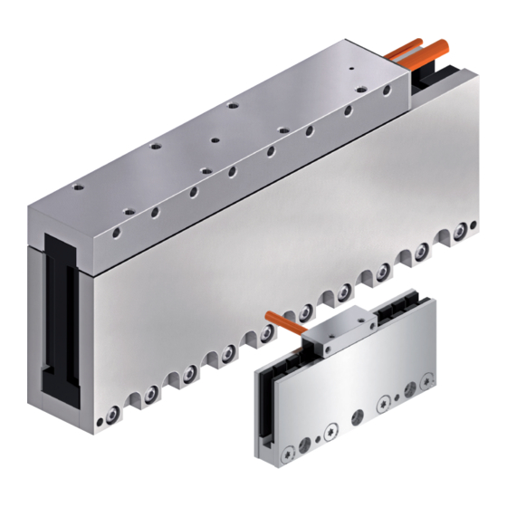
Bosch rexroth MCL Manuals
Manuals and User Guides for Bosch rexroth MCL. We have
1
Bosch rexroth MCL manual available for free PDF download: Project Planning Manual
Bosch rexroth MCL Project Planning Manual (206 pages)
Ironless Linear Motors
Brand:
Bosch
| Category:
Engine
| Size: 8.49 MB
Table of Contents
Table of Contents
3
1 Introduction to the Product
9
Fields of Application
9
Basic Features
10
Setup
10
Comparison Ironless with Ferreous Linear Motors
11
Motor Power Spectrum
12
About this Documentation
12
Editions of this Documentation
12
Document Structure
13
Information Presentation
13
Further Documentation
14
Standards
15
Additional Components
15
Your Feedback
15
2 Important Instructions on Use
17
Appropriate Use
17
Introduction
17
Areas of Use and Application
17
Inappropriate Use
18
3 Safety Instructions for Electric Drives and Controls
19
Definitions of Terms
19
General Information
20
Using the Safety Instructions and Passing Them on to Others
20
Requirements for Safe Use
20
Hazards by Improper Use
21
Instructions with Regard to Specific Dangers
22
Protection against Contact with Electrical Parts and Housings
22
Protective Extra-Low Voltage as Protection against Electric Shock
23
Protection against Dangerous Movements
24
Protection against Electromagnetic and Magnetic Fields During Operation and Mounting
25
Protection against Contact with Hot Parts
26
Protection During Handling and Mounting
26
Battery Safety
26
Protection against Pressurized Systems
27
Explanation of Signal Words and the Safety Alert Symbol
28
4 Technical Data
29
Explanations about Technical Data
29
Introduction
29
Operating Behavior
29
Description of Specified Sizes
33
Indrasize
34
General Technical Data
35
Frame Size 015
36
Data Sheet MCP015
36
Data Sheet MCS015
36
Motor Characteristic Curve Frame Size 015
37
Frame Size 020
38
Data Sheet MCP020
38
Data Sheet MCS020
38
Motor Characteristic Curves Frame Size 020
39
Frame Size 030
41
Data Sheet MCP030
41
Data Sheet MCS030
41
Motor Characteristic Curve Frame Size 030
42
Frame Size 040
44
Data Sheet MCP040
44
Data Sheet MCS040
45
Motor Characteristic Curves Frame Size 040
45
Frame Size 070
48
Data Sheet MCP070
48
Data Sheet MCS070
49
Motor Characteristic Curve Frame Size 070
49
5 Dimension Sheets
53
Specifications
53
Air Gap and Installation Height
53
Installation Dimensions MCL015
54
Installation Dimensions MCL020
55
Parallelism and Symmetry of Machine Parts
56
Dimensional Sheets for MCL015
58
Dimensional Sheets MCL020
60
Dimensional Sheets for MCL030
62
Dimensional Sheets MCL040
64
Dimensional Sheets MCL070
66
6 Identification
69
Type Codes
69
General
69
Type Codes Primary Part MCP
69
Type Code MCS Secondary Part
71
Type Code Frame Size 015
72
Type Code Frame Size 020
74
Type Code Frame Size 030
76
Type Code Frame Size 040
78
Type Code Frame Size 070
80
Identification
82
Identification MCP Primary Part
82
Identification MCS Secondary Part
83
Certification Mark
84
7 Accessories and Options
85
Hall Unit
85
General
85
Hall Unit Function
85
Hall Unit Assembly/Disassembly
88
Ordering Code Separate Hall Unit
89
Hall Unit Adapter Box SHL03.1 for Digital Hall Unit
89
General Mode of Functioning
89
Ordering Code
89
8 Connection Technique
91
Notes
91
Power Connection
91
Connection Cable on Primary Part
91
Assembly Connection Cable on Primary Part
93
Connection Power
94
Installation of Power Connection
96
Sensors
98
Connection Temperature Sensor
98
Connection Hall Unit
98
Assembly Hall Unit Connection Cable
100
Connect Digital Hall Unit
101
Connect Analog Hall Unit
102
Length Measuring System
102
9 Application and Construction Instructions
105
Mode of Functioning
105
Motor Design
105
Design Primary Part
105
Design Secondary Part
106
Frame Size and Frame Length
107
Installation Altitude and Ambient Conditions
108
Environmental Conditions During Operation
109
Type of Protection
110
Acceptances and Approvals
110
Eac
110
Rohs
111
China Rohs 2
111
Magnetic Fields
111
Noise Emission
112
Thermal Behavior
113
Motor Temperature Monitoring
115
Feed Force at Reduced Covering between Primary and Secondary Part
116
Requirements on the Machine Design
118
General
118
Mass Reduction
118
Mechanical Rigidity
118
Protection of the Motor Installation Space
120
Arrangement of Motor Components
120
Single Arrangement
120
Several Motors Per Axis
121
Arrangement of Secondary Parts
127
Vertical Axis
127
Length Measuring System
128
General
128
Selection Criteria for Length Measuring System
128
Linear Guiding Systems
129
Braking Systems and Holding Devices
130
End Position Shock Absorber
131
Axis Cover Systems
131
Motor Control and Regulation
131
General
131
Drive Controllers
132
Control Systems
132
Deactivation Upon EMERGENCY STOP and in the Event of a Malfunction
133
General
133
Deactivation by the Drive
133
Deactivation by a Master Control
134
Deactivation Via Mechanical Braking Device
134
Response to a Power Outage
134
Short-Circuit of DC Bus
136
Position and Velocity Resolution
136
Drive Internal Position Resolution and Position Accuracy
136
Velocity Resolution
137
Thermal Connection - Installation Modes
137
Operation at or Near Motor Standstill
140
10 Motor-Control Combinations
141
General
141
Motor-Control Combinations with Nyce 4000
141
Motor-Control Combinations with Indradrive Cs
142
11 Motor Dimensioning
143
General Procedure
143
Basic Formulae
144
General Movement Equations
144
Feed Forces
145
Average Velocity
148
Trapezoidal Velocity Profile
149
Trapezoidal Velocity Profile
153
Sinusoidal Velocity Profile
154
Duty Cycle and Feed Force
157
General
157
Determining the Duty Cycle
157
Determining the Drive Power
158
General
158
Continuous Power
158
Maximum Output
159
Power Loss
160
Energy Regeneration
160
Efficiency
161
12 Handling, Transport and Storage
163
Delivery Status and Packaging
163
Primary Parts
163
Secondary Parts
163
Testing of Motor Components
163
Factory Checks of the Motor Components
163
Transport and Storage
164
Notes about Transport
164
Information on Storage
165
13 Assembly
167
Basic Precondition
167
Arrangement of Motor Components
167
Installation of Motor Components
168
Air-Gap, Parallelism and Symmetry of the Motor Components
168
Fastening Secondary Part
169
Fastening the Primary Part
171
Electrical Connection
173
14 Commissioning, Operation and Maintenance
175
General
175
General Requirements
175
Checking All Electrical and Mechanical Components
175
Tools
176
General Commissioning Procedure
176
Parameterization
178
General
178
Entering Motor Parameters
178
Motor Parameter at Parallal Arrangement
178
Entering Length Measuring System Parameter
179
Entering Drive Limitations and Application-Related Parameters
180
Determining the Polarity of the Linear Scale
181
Commutation Adjustment
182
General
182
Sinusoidal Procedure
184
Hall Sensor Procedure
184
Measuring Procedure: Measuring of the Relation between Primary and Secondary Part
185
Setting and Optimizing the Control Loop
187
General Procedure
187
Parameter Value Assignments and Optimization of Gantry Axes
190
Estimating the Moved Mass Using a Velocity Ramp
191
Maintenance and Checking of Motor Components
193
General
193
Checking of Motor and Additional Components
193
Electrical Check of Motor Components
193
Operation with Third-Party Controllers
194
Environmental Protection and Disposal
194
Environmental Protection
194
Disposal
194
15 Service and Support
197
Index
199
Advertisement
Advertisement
Related Products
Bosch Rexroth MKE E Series
Bosch Rexroth MKE U Series
Bosch Rexroth MAD
Bosch Rexroth MAF
Bosch rexroth MSK Series
Bosch Rexroth MKE
Bosch Rexroth MKE Series
Bosch rexroth MBT
Bosch Rexroth IndraDyn A Series
Bosch rexroth Hagglunds CBp
Bosch Categories
Dishwasher
Washer
Oven
Power Tool
Dryer
More Bosch Manuals
Login
Sign In
OR
Sign in with Facebook
Sign in with Google
Upload manual
Upload from disk
Upload from URL