abb TTF300 Manuals
Manuals and User Guides for abb TTF300. We have 8 abb TTF300 manuals available for free PDF download: Commissioning Instructions, Operating Instruction, Manual, Safety Instructions, User Manual
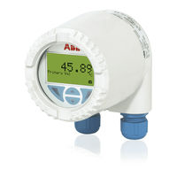
ABB TTF300 Commissioning Instructions (364 pages)
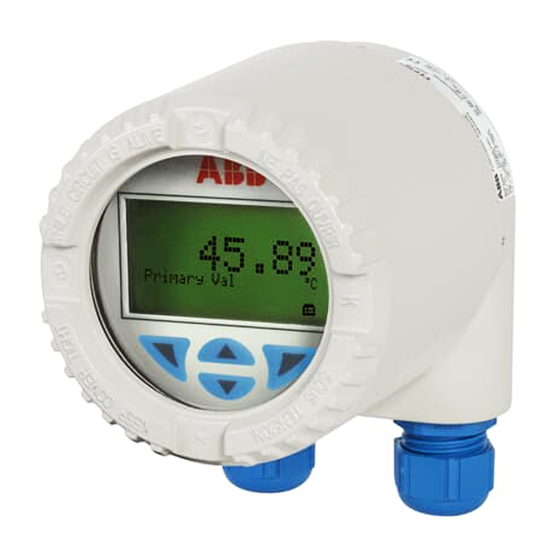
Field-mounted temperature transmitter
Brand: ABB
|
Category: Transmitter
|
Size: 4.05 MB
Table of Contents
Advertisement

ABB TTF300 Operating Instruction (92 pages)
Field-mount temperature transmitter
Brand: ABB
|
Category: Transmitter
|
Size: 3.19 MB
Table of Contents

ABB TTF300 Operating Instruction (72 pages)
Field-mount temperature transmitter for all communications protocols, Redundancy thanks to two inputs
Brand: ABB
|
Category: Transmitter
|
Size: 3.42 MB
Table of Contents
Advertisement

abb TTF300 Operating Instruction (78 pages)
Field mounted Temperature Transmitter
Brand: abb
|
Category: Temperature Controller
|
Size: 1.07 MB
Table of Contents

ABB TTF300 Manual (48 pages)
Field-mount temperature transmitter
Brand: ABB
|
Category: Transmitter
|
Size: 2.09 MB
Table of Contents

ABB TTF300 Commissioning Instructions (40 pages)
Field-mounted temperature transmitters
Brand: ABB
|
Category: Transmitter
|
Size: 0.75 MB
Table of Contents

ABB TTF300 User Manual (24 pages)
H Series temperature transmitter
Brand: ABB
|
Category: Transmitter
|
Size: 1.52 MB
Table of Contents

ABB TTF300 Safety Instructions (24 pages)
Temperature Transmitter, SILl 2 / 3
Brand: ABB
|
Category: Transmitter
|
Size: 2.27 MB
Table of Contents
Advertisement