Sign In
Upload
Manuals
Brands
ABB Manuals
I/O Systems
Remote I/O RIO600
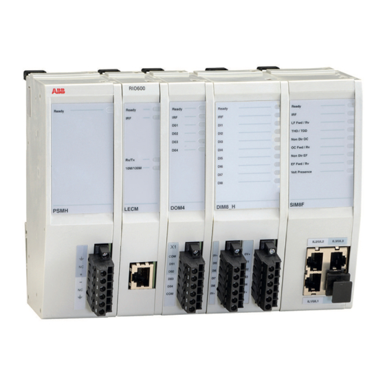
ABB Remote I/O RIO600 Manuals
Manuals and User Guides for ABB Remote I/O RIO600. We have
1
ABB Remote I/O RIO600 manual available for free PDF download: Installation And Commissioning Manual
ABB Remote I/O RIO600 Installation And Commissioning Manual (312 pages)
Brand:
ABB
| Category:
I/O Systems
| Size: 15.2 MB
Table of Contents
Table of Contents
9
Section 1 Introduction
15
This Manual
15
Intended Audience
15
Product Documentation
15
Product Documentation Set
15
Document Revision History
16
Related Documentation
16
Symbols and Conventions
16
Symbols
16
Document Conventions
17
Section 2 General Security Deployment Guidelines
19
General Security
19
System Hardening Rules
19
Section 3 RIO600 Overview
21
Overview
21
Product Version History
24
Module Configuration
25
Web HMI
27
PCM600 Tool
28
PCM600 and RIO600 Connectivity Package Version
29
Communication
29
TCP/IP-Based Protocols and Used IP Ports
30
Section 4 Unpacking, Inspecting and Storing
31
Removing Transport Packaging
31
Inspecting the Product
31
Identifying the Product
31
Checking Delivery Items
31
Returning a Product Damaged in Transportation
32
Storing
32
Section 5 Installing
33
Mounting Modules
33
Configuration Examples
39
Connecting Wires
41
Connecting Power Supply
41
Connecting Ethernet Cable
44
Connecting Binary Input Signals
44
Connecting Binary Output Signals
46
Connecting Rtd/Ma Signals
47
Connecting AOM4 Signals
50
Connecting SIM8F Sensor Signals
51
Connecting SIM4F Sensor Signals
54
Connecting Smart Control Module Signals
56
Connecting RIO600 to a PC
62
Checking the Connection to RIO600
63
Section 6 Commissioning
65
Parameter Setting
65
Operating Parameter Settings LECM
65
Standalone Configuration
66
Intermodule Communication
66
Operating Parameter Settings DIM8H and DIM8L
66
Binary Input Debounce Time (Filter Time)
67
Binary Input Inversion
68
Oscillation Suppression
68
Operating Parameter Settings DOM4
69
Operating Parameter Settings of Rtd/Ma Module
70
Selection of Output Value Format
71
Linear Input Scaling
72
Measurement Chain Supervision
72
Calibration
73
Limit Value Supervision
73
Deadband Supervision
74
Operating Parameter Settings of AOM4
75
Calibration
76
Output Channel Supervision
76
Deadband Supervision
76
Operating Parameter Settings of SIM8F Module
77
Functions Available in SIM8F
79
Measurement Functions
80
Power Quality Measurement Functions (Harmonics)
93
Three-Phase Current Fault Detection
97
Earth-Fault Fault Detection
108
Voltage Presence Indication
143
Negative-Sequence Overcurrent Indication NSPTOC
145
Fuse Failure Supervision SEQSPVC
147
Inrush Detector INRPHAR
152
UPS Power Failure Monitoring
154
Calibration
155
Operating Parameter Settings of SIM4F Module
155
Functions Available in SIM4F
157
Measurement Functions
157
Three-Phase Current Fault Detection
157
Earth-Fault Detection
158
Negative-Sequence Overcurrent Indication NSPTOC
158
Inrush Detector INRPHAR
158
Fault Passage Indicator FPIPTOC
158
Calibration
167
Operating Parameter Settings of SCM Module
167
Functions Available in SCM
167
Three-Position Earthing Switch or Two-Position Earthing Switch or Two-Position Disconnector Switch or Circuit Breaker Control Application
167
Generic Four Inputs and Four High Speed Power Outputs
172
Trip Circuit Supervision TCSHSCBR/TCSLSCBR
173
Test Mode Handling
175
Channel Output Value Handling
175
Local/Remote Mode
176
Time Synchronization
176
SNTP Time Synchronization
177
Modbus Time Synchronization
177
GOOSE Performance
178
Section 7 Modbus TCP Communication
179
Modbus TCP/IP
179
Connection to Client
179
Protocol Server Attachment to a Client
179
TCP/IP Link
179
Modbus TCP/IP Diagnostic Counters over Web HMI
180
Common Modbus TCP/IP Diagnostic Counters
180
Supported Modbus Function Codes
180
Modbus Data Implementation
181
Change Events and Time Synchronization
181
Control Operations
181
Application Data Compatibility
181
Data Mapping Principles
182
Default Data Organization
182
Data in Monitoring Direction
182
One-Bit Data Mapping
182
Digital Input Data
182
Measurand Registers
183
Register Value Update
183
Primary Values
184
Register Size
184
Control Operations
184
Control Functions
184
Exception Codes
185
System Status Register
185
Module Information
186
Modbus Time Synchronization
186
Parameter Settings
187
Module Reserved Channel Concept
189
RTD Range Information
189
Reporting Reserved Addresses
190
Function Code and Addressing Region Mapping
191
Modbus Point List
192
SSR1 System Status Register (1) Device Health
192
SSR2 System Status Register (2) Device Alive Register
193
Time Synchronization
193
Module Identification
194
LD0.DIM8GGIO/LD0.DIM8LGGIO Physical I/O States
194
LD0.DOMGGIO Physical I/O States
199
LD0.RTDGGIO Physical I/O Values
203
LD0.RTDGGIO RTD Channel Range Information
210
LD0.AOMGGIO Physical I/O Values
213
LD0.PHPTOC Phase Overcurrent Fault Detection
215
LD0.DPHPTOC Three-Phase Directional Overcurrent Fault Detection
217
LD0.CMHAI Current Total Demand Distortion
218
LD0.VMHAI Voltage Total Demand Distortion
219
LD0.EFPTOC Non-Directional Earth-Fault Detection
219
LD0.DEFPTOC Directional Earth-Fault Detection
220
LD0.MFAPSDE Multifrequency Admittance Protection (Earth-Fault Indication)
220
LD0.PHSVPR Voltage Presence
222
LD0.NSPTOC Negative-Sequence Overcurrent Fault Detection
222
LD0.FPIPTOC Fault Direction Indication
223
LD0.SEQSPVC Fuse Failure Supervision
223
LD0.INRPHAR Inrush Detector
224
Binary Writable Signals for SIM8F
224
Binary Writable Signals for SIM4F
225
LD0.PWRRDIR Phase Load Flow Direction
226
LD0.PHPTOC Phase Overcurrent Fault Detection
227
LD0.DPHPTOC Three-Phase Directional Overcurrent Fault Detection
228
LD0.EFPTOC Non-Directional Earth-Fault Detection
229
LD0.DEFPTOC Directional Earth-Fault Detection
229
LD0.CMMXU Phase Current Measurements
229
LD0.VMMXU Voltage Measurements
231
LD0.PEMMXU Power Measurements
235
LD0.RESCMMXU Residual Current Measurement
238
LD0.RESVMMXU Residual Voltage Measurement
239
LD0.CAVMMXU Average Current Measurements
240
LD0.RCAVMMXU Average Current Measurements
241
LD0.CMAMMXU Peak Current Measurements
242
LD0.VAVMMXU Average Voltage Measurements
243
LD0.VMAMMXU Peak Voltage Measurements
244
LD0.PEAVMMXU Average Power Measurements
245
LD0.PEMAMMXU Peak Power Measurements
246
LD0.EMMTR Energy Measurement
247
LD0.MFAPSDE Multifrequency Admittance Protection (Earth-Fault Indication)
249
SCM Application Types
249
Binary Readable Signals of SCM
250
Binary Writable Signals for SCM
259
Supervision Data
266
Section 8 Using the Web HMI
269
Accessing the Web HMI
269
Navigating in the Menu
269
Selecting the Fault View
269
Selecting the Status View
270
Selecting the Configuration View
274
Selecting the Communication View
278
Section 9 Troubleshooting
281
Checking LED Indications
281
Behavior During IRF Condition
285
Restoring Communication
288
Restoring Factory Settings
289
Ping Command Response
290
Troubleshooting Inactive I/O Modules
291
SIM8F/SIM4F Measurement Quality
292
Contacting Customer Support
292
Section 10 Technical Data
293
Section 11 Device and Functionality Tests
301
Section 12 Glossary
307
Advertisement
Advertisement
Related Products
ABB IMASI23
ABB Symphony IMDSI13
ABB Symphony IMDSI14
ABB Symphony IMDSI22
ABB Symphony IMCIS22
ABB Symphony IMQRS22
ABB IRB 2400/10
ABB IRBT 2005
ABB i-bus EIB
ABB IHBF 24 C
ABB Categories
Industrial Equipment
Controller
Measuring Instruments
Battery Charger
DC Drives
More ABB Manuals
Login
Sign In
OR
Sign in with Facebook
Sign in with Google
Upload manual
Upload from disk
Upload from URL