Sign In
Upload
Manuals
Brands
ABB Manuals
Robotics
IRB6400
ABB IRB6400 Manuals
Manuals and User Guides for ABB IRB6400. We have
2
ABB IRB6400 manuals available for free PDF download: Electrical Troubleshooting Manual, Assembly Manuallines
ABB
IRB6400
Electrical Troubleshooting Manual
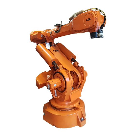
ABB IRB6400 Electrical Troubleshooting Manual (510 pages)
INDUSTRIAL ROBOT & CONTROL SYSTEM
Brand:
ABB
| Category:
Robotics
| Size: 5.64 MB
Table of Contents
(Cont)
5
Table of Contents
4
Table of Contents
5
Introduction
10
Identification
11
Maintenance
12
Tools
13
This Manual
14
Chapter Descriptions
15
D. Glossary
16
Appendices Descriptions
16
Signs and Symbols
17
1 Safety
18
General Safety
22
Safety Features
23
Safety Guidelines
24
Safety During Maintenance
26
Safety During Programming
26
Safety Control Chain of Operation
27
Risks Associated with Live Parts
29
Limitation of Liability
30
Related Information
30
2 Computer System
31
Overview
34
Diagram 2-1 Computer System and System Boards
34
System Description
35
Diagram 2-2 Block Diagram
36
Troubleshooting
37
General
37
Diagnostics
40
Board Descriptions
41
Robot Computer DSQC 326
42
Main Computer DSQC 316
43
Memory Board DSQC 317/6 Mb (DSQC 321/4Mb)
44
Power Supply Unit DSQC 258
45
2.4.5 System Board DSQC 256A
46
Digital I/O Board DSQC 223
48
Combined I/O Board DSQC 315
49
Analog I/O Board DSQC 209
50
Remote I/O Board DSQC 239
51
Axis Board DSQC 233
52
Serial Measurement Board (SMB)
53
Teach pendant
54
Component Cross Reference
55
List of Circuit Diagrams
56
Component Location Figures
58
Figure 2-2 Connectors
60
Figure 2-3 SMB
62
Figure 2-5 Teach pendant
66
3 Loading System Software
68
Overview
71
Floppy Disk
72
Software Loading Procedure
73
Parameter Loading Procedure
76
Resolver Revolution Counter Update
77
List of Circuit Diagrams
81
Component Location Figures
83
Figure 3-2 Floppy Disk Drive
85
Figure 3-3 Robot Calibration Position
87
4 Power on
95
Overview
98
AC Power Distribution
99
DC Power Distribution
100
Component Cross Reference
103
List of Circuit Diagrams
104
Component Location Figures
106
Figure 4-2 Inside Swing Gate
108
Figure 4-3 Brake Push Buttons
110
Figure 4-5 Operator's Panel
114
5 Motor On/Dual Run Chain
119
Overview
119
Diagram 5-1 Computer System and System Board
120
Manual (Reduced or Full) Speed Mode Circuit
121
Run Chain 1
121
Run Chain 1 - Manual Stop Circuit
122
Run Chain 1 - General Stop (GS) Circuit
123
Run Chain 1 - Emergency Stop (ES) Circuit
124
Run Chain 1 - Limit (LIM) Circuit
125
Run Chain 1 - Completion
126
Run Chain 2
127
Run Chain 2 - Manual Stop Circuit
128
Run Chain 2 - General Stop Circuit
129
5.2.10 Run Chain 2 - Emergency Stop Circuit
130
5.2.11 Run Chain 2 - Limit Circuit
131
5.2.12 Run Chain 2 - Completion
132
AUTO Mode Circuit
133
Run Chain 1
133
Run Chain 2
134
Component Cross Reference
135
List of Circuit Diagrams
137
Component Location Figures
139
Figure 5-3 System Board K1CR & K2CR
143
Figure 5-6 Operator's Panel
149
Figure 5-7 Power Unit
151
Figure 5-8 R1.MP
153
Figure 5-9 Teach pendant
155
Emergency Stop Circuitry
158
Emergency Stop
160
Emergency Stop - Run Chain 1
161
Emergency Stop - Run Chain 1
162
Emergency Stop - Run Chain 2
164
Emergency Stop - Reset Circuit
165
Component Cross Reference
166
List of Circuit Diagrams
168
Component Location Figures
170
Figure 6-2 Computer System & System Board
172
Figure 6-3 Back Plane AP80
174
Figure 6-4 Operator's Panel
176
Figure 6-5 Customer Connections XS3/XT3
178
7 Power Unit
183
Diagram 7-1 Rectifier Board
187
Component Cross Reference
189
List of Circuit Diagrams
191
Component Location Figures
193
Figure 7-3 K1CR & K2CR on System Board
197
8 Brake Circuitry
202
Manual Brake Release Circuit
203
Motors on Brake Release
204
Component Cross Reference
206
List of Circuit Diagrams
208
Component Location Figures
210
Figure 8-2 System Board
212
Figure 8-3 Robot Brake Buttons
214
Figure 8-4 Power System Board Connections
216
Figure 8-5 Robot Axes
218
Motor & Resolver Circuitry
221
Motor & Resolver Circuitry
223
Overview
223
Diagram 9-1 Closed Loop System
223
Computer
224
Main Computer
224
Memory Board
224
Robot Computer
225
Drive System Boards
226
Rectifier
226
Diagram 9-2 Rectifier
226
Drive Unit
228
Diagram 9-3 Drive Board
228
Motors
229
Diagram 9-4 Simplified Motor
229
Diagram 9-5 'Y' Motor Wiring Configuration
230
Resolver
232
Diagram 9-6 Resolver Coil Relationships
232
Serial Measurement Board (SMB)
233
Component Cross Reference
235
List of Circuit Diagrams
237
Component Location Figures
239
Figure 9-2 Drive System Boards
241
Figure 9-3 Robot Axis Motors
243
Figure 9-4 Drive Connectors
245
10 Calibration Procedures
250
Rough" Resolver Calibration Procedure
251
Manually Entering Calibration Values
257
Precision Resolver Calibration Procedure
261
Calibrating Axis 1
262
Calibrating Axis 2-6
263
Counter Updating Procedure
270
Inputs & Outputs
279
I/O Boards
280
Analog I/O Board DSQC 209
281
Combined I/O Board DSQC 315
282
Remote I/O Board DSQC 239
283
Board Connections
284
External I/O Connections (Conn. Option 31X)
285
Internal I/O Connections (Conn. Option 34X)
289
Relay Unit (Conn. Option 37X)
292
VAC Modules (Conn. Option 35X)
294
Manually Operated I/O
295
Component Cross Reference
297
List of Circuit Diagrams
299
Component Location Figures
301
Figure 11-2 Screw Terminals
303
Figure 11-3 120 VAC I/O Connector
305
Error Messages
308
Error Messages
309
A1. Indicating Errors
309
A2. Types of Error Messages
310
A3. Error Codes
314
A3.1 Operational Error Messages
314
A3.2 System Error Messages
316
A3.3 Hardware Error Messages
323
A3.4 Programming Error Messages
342
A3.5 Motion Error Messages
366
A3.6 Operator Error Messages
374
A3.7 I/O & Communication Error Messages
376
B. Parts Lists
385
B1.3 Teach pendant
386
B1.6 Drive System
387
B1.8 Miscellaneous
388
B2. Suggested Spare Parts List
389
B2.4 Upper Arm
390
B2.6 Control
391
Connectors & Cables
394
Connectors & Cables
395
C. Connectors & Cables
396
C1. Robot Arm Cables
396
C2. Control Cabinet Cables
397
C3. Miscellaneous Cables
399
C4. Signal Cable, Axis 1
400
C5. Signal Cable, Axis 5
401
Power Cable, Axis 5
402
C7. Signal Cable, Axis 6
403
C8. Power Cable, Axis 6
404
C9. Signal Cable, Axis 2
405
C10. Power Cable, Axis 2
406
C11. Signal Cable, Axis 3
407
C12. Power Cable, Axis 3
408
C13. Control Cable, Signal
409
C14. Control Cable, Power
410
C15. Customer Cable, Signal
411
C16. Customer Cable, Power
412
C17. Lower Cable Assembly
413
C18. Upper Cable Assembly
415
C19. Cable, Customer Connection
417
C20. Cable, M94A
418
C21. Cable, M94A Control Wiring X-Reference
423
C22. Connectors
428
Circuit Diagrams
444
Circuit Diagrams
445
Sheet Numbering
446
E. Circuit Diagrams
446
Connector Labeling
447
E2. Connector Labeling
447
Component Labeling
448
E3. Component Labeling
448
Sheet Referencing
449
E4. Sheet Referencing
449
Relay Labeling
450
E5. Relay Labeling
450
Key Switch Contacts
451
E7. Symbols and Abbreviations
452
Advertisement
ABB IRB6400 Assembly Manuallines (212 pages)
INDUSTRIAL ROBOT
Brand:
ABB
| Category:
Robotics
| Size: 3.25 MB
Table of Contents
Introduction
6
What You Must Know to Use the Robot
11
Robot Components
12
Robot Identification
13
Symbols Used in this Manual
14
Safety
16
Table of Contents
16
General Safety
18
Safety Features
19
Safety Guidelines
20
Safety During Maintenance
21
Safety During Programming
22
Safety Control Chain of Operation
23
Risks Associated with Live Parts
24
Robot Lifting
28
Releasing Axes Brakes Manually
32
Restricting Axes Movement Mechanicall y
33
Axis
35
General Maintenance
36
Axis
37
Maintenance Schedule
37
General Instructions
38
Maintenance Instructions
38
Axis
39
Lubricating Axis 1 Gear Reduction Unit (S59)
40
Disassembly/Assembly
40
Lubricating Axes 2 & 3 Gear Units (S35)
41
Disassembly/Assembly
41
Oil Change Gearbox, Axis 4 (U61)
42
Guidelines IRB
42
Oil Change for Axis 5 Gearbox (W8)
44
Lubricating Axis 6 Gearbox (F17)
46
Checking Axis 1 Mechanical Stop
47
Changing Measuring System Battery
48
Changing Axis 1 Cooling Filter
49
Changing Control Air Conditioner Filter
50
Changing Control Memory Battery Backup
51
Adjusting Axis 4 Gear Play
52
Adjusting Play between Intermediate Gear (U74)
52
Final Gear (U41)
52
Adjusting Play between Axis 4 Motor Pinion
53
Checking Axis 5 Gear Play
53
Adjusting Axis 5 Gear Play
54
Adjusting Axis 5 Bearings Pre-Tension
55
Checking Axis 6 Gear Reduction Unit Play
56
Tool List
59
Disassembly/Assembly
61
Lubricating Axis 1 Large Bearing (S46)
39
Axis 1
62
Motor (S16) Removal
63
Motor (S16) Installation
65
Gear Reduction Unit (S59) Removal
67
GEAR REDUCTION UNIT (S59) Installation
70
Bearing (B47) Removal
73
Bearing (B47) Installation
76
Disassembly/Assembly
81
Axes 2 & 3
82
Motor (S71) Removal
83
Motor (S71) Installation
85
Gear Reduction Unit (S35) Removal
87
GEAR REDUCTION UNIT (S35) Installation
88
Parallel Bar (L42) Removal
92
Parallel Bar (L42) Installation
95
Bearings (L40) & (L56) Removal
96
Upper Arm Assembly Removal
101
Upper Arm Assembly Installation
103
Axis 4
108
Motor (U83) Removal
109
Motor (U83) Installation
112
INTERMEDIATE GEAR UNIT (U75) Removal
115
INTERMEDIATE GEAR UNIT (U75) Installation
118
Final Gear (U41) Removal
120
Final Gear (U41) Installation
123
Tube Shaft (U19) Removal
125
Tube Shaft (U19) Installation
126
Robot Calibration
170
Calibration Procedures
172
Overview
172
Rough" Resolver Calibration Procedure
173
Manually Entering Calibration Values
179
Precision Resolver Calibration Procedure
183
Calibrating Axis 1
184
Calibrating Axis 2-6
185
Counter Updating Procedure
192
Advertisement
Related Products
ABB IRB 640
ABB IRB 6600ID - 185/2.55
ABB IRB 6640ID - 200/2.55
ABB IRB 6640ID - 170/2.75
ABB IRB 6650S Series
ABB IRB 6700 Series
ABB IRB 6640ID
ABB IRB 6620
ABB IRB 6790
ABB IRB 6730
ABB Categories
Industrial Equipment
Controller
Measuring Instruments
Battery Charger
DC Drives
More ABB Manuals
Login
Sign In
OR
Sign in with Facebook
Sign in with Google
Upload manual
Upload from disk
Upload from URL