Sign In
Upload
Manuals
Brands
ABB Manuals
Robotics
DressPack IRB 6700
ABB DressPack IRB 6700 Manuals
Manuals and User Guides for ABB DressPack IRB 6700. We have
2
ABB DressPack IRB 6700 manuals available for free PDF download: Product Manual
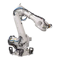
ABB DressPack IRB 6700 Product Manual (575 pages)
Brand:
ABB
| Category:
Robotics
| Size: 18.8 MB
Table of Contents
Table of Contents
5
Overview of this Manual
9
Product Documentation, IRC5
11
How to Read the Product Manual
13
Introduction to Safety Information
15
General Safety Information
16
Introduction to General Safety Information
16
Safety in the Manipulator System
17
Connection of External Safety Devices
17
Validity and Responsibility
17
Non-Voltage Related Risks
18
Safety Risks During Installation and Service Work on Manipulators
18
Spare Parts and Special Equipment
18
CAUTION - Hot Parts May Cause Burns
21
Safety Risks Related to Tools/Work Pieces
22
Safety Risks Related to Pneumatic/Hydraulic Systems
23
Safety Risks During Operational Disturbances
24
Risks Associated with Live Electric Parts
25
Safety Actions
27
Safety Fence Dimensions
27
Fire Extinguishing
28
Emergency Release of the Manipulator's Arm
29
Brake Testing
30
Risk of Disabling Function "Reduced Speed 250 MM/S
31
Safe Use of the Flexpendant
32
Work Inside the Manipulator's Working Range
33
Safety Stops
34
Definition of Emergency Stop
34
What Is an Emergency Stop
34
Classification of Stops
35
Emergency Stop Devices
35
Safety Related Instructions
36
Introduction to Safety Signals
36
Safety Signals in the Manual
36
Safety Symbols on Manipulator Labels
38
DANGER - Moving Manipulators Are Potentially Lethal
43
DANGER - First Test Run May Cause Injury or Damage
44
WARNING - the Brake Release Buttons May be Jammed after Service Work
45
DANGER - Make Sure that the Main Power Has Been Switched off
46
WARNING - the Unit Is Sensitive to ESD
47
WARNING - Safety Risks During Handling of Batteries
48
WARNING - Safety Risks During Work with Gearbox Lubricants (Oil or Grease)
49
2 Installation and Commissioning
51
Introduction
51
Unpacking
52
Pre-Installation Procedure
52
Checking the Pre-Requisites for Installation
52
Floor Mounted
53
Loads on Foundation, Robot
53
Operating Conditions, Robot
54
Protection Classes, Robot
54
Requirements, Foundation
54
Storage Conditions, Robot
54
Working Range
55
Illustration, Working Range IRB 6700 - 205/2.80
56
Illustration, Working Range IRB 6700 - 235/2.65
56
Illustration, Working Range IRB 6700 - 175/3.05
57
Illustration, Working Range IRB 6700 - 150/3.20
58
Turning Radius
59
Risk of Tipping/Stability
60
Shipping and Transport Position
60
Main Dimensions
61
Dimensions for Different Robot Variants
61
On-Site Transportation
62
Robot Transportation Precautions
62
Transport Position with a Transport Support
65
Recommended Transport Support
66
Securing the Robot
67
On-Site Installation
69
Lifting Robot with Fork Lift
69
Fork Lift Device Set
69
Lifting the Base Plate
72
Hole Configuration
72
Securing the Base Plate
73
Base Plate, Grooves and Holes
75
Guide Sleeve
75
Base Plate
76
Recommendations, Quality
76
Lifting the Robot with Roundslings
78
Attaching the Roundslings
78
Manually Releasing the Brakes
82
Location of Brake Release Unit
82
Releasing the Brakes
82
Supplying Power to Connector R1.MP
83
Orienting and Securing the Robot
84
Attachment Screws
84
Loads
86
Fitting Equipment to the Robot
87
Frame (Hip Load)
87
Upper Arm
88
Allowed Positions for Attachment Holes
89
Holes for Fitting Extra Equipment
89
Upper Arm, Lower Arm and Frame
90
Tool Flange, Standard
91
Tool Flange, Leanid
92
Restricting the Working Range
93
Introduction
93
Mechanically Restricting the Working Range of Axis 1
94
Installation, Mechanical Stops Axis 1
95
Electrical Connections
96
Robot Cabling and Connection Points
96
Installing the Signal Lamp (Option)
97
Installation of Options
97
3 Maintenance
99
Introduction
99
Maintenance Schedule and Expected Component Life
100
Specification of Maintenance Intervals
100
Maintenance Schedule
101
Activities and Intervals, Standard Equipment
101
Expected Component Life
103
Expected Component Life - Protection Type Standard
103
Inspection Activities
104
Inspecting the Oil Level in Axis-1 Gearbox
104
Inspecting the Oil Level in Axis-2 Gearbox
107
Inspecting the Oil Level in Axis-3 Gearbox
109
Inspecting the Oil Level in Axis-4 Gearbox
111
Inspecting the Oil Level in Axis-5 Gearbox
113
Inspecting the Oil Level in Axis-6 Gearbox
115
Inspecting the Balancing Device
118
Check for Damage
119
Check for Dissonance
119
Check for Contamination / Lack of Free Space
121
Inspecting the Cable Harness
122
Inspection, Information Labels
124
Inspecting, Mechanical Stop Pin, Axis 1
128
Location of Mechanical Stop Pin
128
Inspecting, Mechanical Stop Pin
129
Inspecting, Additional Mechanical Stops
130
Inspecting the Fork Lift Device Set
132
Inspecting the Dampers
134
Inspecting, Signal Lamp (Option)
136
Replacement/Changing Activities
137
Type of Lubrication in Gearboxes
137
Changing Oil, Axis-1 Gearbox
138
Location of Oil Plugs
138
Usage of Oil Dispenser
138
Draining the Axis-1 Gearbox
139
Filling Oil into the Axis-1 Gearbox
140
Changing Oil, Axis-2 Gearbox
143
Draining the Axis-2 Gearbox
144
Filling Oil into the Axis-2 Gearbox
145
Changing Oil, Axis-3 Gearbox
148
Draining the Axis-3 Gearbox
149
Filling Oil into the Axis-3 Gearbox
150
Changing Oil, Axis-4 Gearbox
153
Changing Oil, Axis-5 Gearbox
157
Filling Oil into the Axis-5 Gearbox
159
Changing Oil, Axis-6 Gearbox
161
Filling Oil into the Axis-6 Gearbox
163
Replacing the SMB Battery
165
Location of SMB Battery
165
Lubrication Activities
168
Lubricating the Spherical Roller Bearing, Balancing Device
168
Lubricating the Spherical Roller Bearing
169
Cleaning Activities
170
Cleaning, Robot
170
Cleaning with Water and Steam
170
Cables
171
4 Repair
173
Introduction
173
General Procedures
174
Performing a Leak-Down Test
174
Mounting Instructions for Bearings
175
Assembly of All Bearings
175
Assembly of Tapered Bearings
175
Greasing of Bearings
175
Mounting Instructions for Seals
177
Flange Seals and Static Seals
178
O-Rings
178
Attaching Lifting Accessories
179
Arm System (Including the Frame)
179
Attachment Points of Lifting Accessory
179
Attaching the Lifting Accessories
180
Robot Position
180
Lower and Upper Arm Unseparated
183
Lifting the Upper Arm
188
Complete Robot
191
Removing the Cable Harness
191
Location of the Cable Harness
191
Preparations before Removing the Cable Harness
192
Removing the Cable Harness - Upper Arm and Wrist
192
Retrieving Access to the Wrist Cabling
193
Disconnecting the Axis-6 Motor Cables
195
Disconnecting the Axis-5 Motor Cables
196
Disconnecting the Axis-3 and Axis-4 Motor Cables
197
Removing the Cable Harness - Wrist and Upper Arm
198
Removing the Cable Harness - Base, Frame and Lower Arm
203
Disconnecting the Axis-1 and Axis-2 Motor Cables
204
Preparations before Disconnecting the SMB Unit
205
Disconnecting the BU Unit
206
Removing the Cable Harness in the Base
207
Removing the Cable Harness in the Frame
207
Removing the Cable Harness in the Lower Arm
210
Refitting the Cable Harness
211
Consumables
212
Refitting the Cable Harness - Base, Frame and Lower Arm
212
Refitting the Cable Harness in the Frame and the Upper Arm
213
Refitting the Cable Harness in the Base
216
Refit and Reconnect the SMB and BU Units
218
Reconnecting the Axis-1 and Axis-2 Motor Cables
220
Refitting the Cable Harness - Lower Arm
222
Refitting the Cable Harness - Upper Arm
223
Connecting the Axis-3 and Axis-4 Motor Cables
227
Connecting the Axis-5 Motor Cables
229
Connecting the Axis-6 Motor Cables
231
Concluding Procedures
234
Replacing the SMB
235
Location of SMB Unit
235
Disconnecting and Removing the SMB Unit
236
Refitting the SMB Unit
237
Refitting the SMB Battery
239
Replacing the Brake Release Unit
241
Location of BU Unit
241
Removing the Brake Release Unit
242
Refitting the Brake Release Unit
244
Upper and Lower Arms
246
Location of the Upper Arm
246
Replacing the Upper Arm
246
Removing the Upper Arm
247
Refitting the Upper Arm
259
Location of the Wrist
274
Replacing the Wrist
274
Removing the Wrist
275
Removing the Turning Disk
276
Removing the Process Turning Disk
277
Refitting the Wrist
283
Location of the Turning Disk
294
Replacing the Turning Disk
294
Location of the Lower Arm
297
Replacing the Lower Arm
297
Removing the Lower Arm
298
Unloading the Balancing Device
299
Preparations to Remove the Shaft
301
Removing the Shaft in the Link Ear
301
Removing Brackets
304
Refitting the Lower Arm
317
Refitting the Front Shaft of the Balancing Device
336
Concluded Refitting of the Front Shaft
337
Location of Spherical Roller Bearing
340
Replacing Spherical Roller Bearing, Link Ear
340
Frame and Base
340
Removing the Spherical Roller Bearing
341
Removing the Shaft in the Front
345
Removing the Spherical Roller Bearing, Link Ear
346
Refitting the Spherical Roller Bearing
347
Refitting the Spherical Roller Bearing, Link Ear
347
Preparations, Lifting Accessory
349
Unloading a New Spare Part, Balancing Device
350
Location of the Balancing Device
354
Replacing the Balancing Device
354
Removing the Balancing Device
355
Removing the Axes in the Rear
359
Removing the Axis in the Front
360
Refitting the Balancing Device
361
Refitting the Rear Shafts
362
Replacing the Rear Bearing of the Balancing Device
367
Removing the Bearing, Cradle
368
Removing the Shaft End, Cradle
371
Refitting the Bearing, Cradle
372
Refitting the Shaft End
372
Location of the Stop Pin
376
Replacing the Stop Pin
376
Removing the Stop Pin
377
Refitting the Stop Pin
378
Prerequisite
379
Unloading the Balancing Device
379
Press Tool and Hydraulic Cylinder
380
Restoring the Balancing Device
383
Location of the Axis-1 Motor
386
Replacing the Axis-1 Motor
386
Removing the Axis-1 Motor
387
Preparations Prior to Refitting Motor
390
Refitting the Axis-1 Motor
390
Securing the Axis-1 Motor
391
Connecting the Motor Cables
393
Location of the Motor
396
Replacing the Axis-2 Motor
396
Removing the Motor
397
Disconnecting the Motor Cables
398
Removing the Axis-2 Motor
399
Refitting the Motor
401
Securing the Axis-2 Motor
402
Location of the Axis-3 Motor
407
Replacing the Axis-3 Motor
407
Location of the Axis-4 Motor
418
Replacing the Axis-4 Motor
418
Location of the Axis-5 Motor
427
Replacing the Axis-5 Motor
427
Removing the Axis-5 Motor
428
Location of Axis-6 Motor
440
Replacing the Axis-6 Motor
440
Removing the Axis-6 Motor
441
Refitting the Axis-6 Motor
444
Replacing the Axis-1 Gearbox
449
Gearboxes
449
Location of the Axis-1 Gearbox
449
Removing the Axis-1 Gearbox
451
Disconnecting the Axis-1 Motor Cables
456
Lifting Away the Complete Arm System
460
Removing Axis-1 Gearbox
461
Refitting the Axis-1 Gearbox
462
Connecting the Axis-1 Motor Cables
473
Location of the Axis-2 Gearbox
477
Replacing the Axis-2 Gearbox
477
Space Required Beside
477
Removing the Axis-2 Gearbox
479
Disconnecting the Axis-2 Motor Cables
486
Removing and Lifting Away the Lower and Upper Arm
490
Refitting the Axis-2 Gearbox
492
Lifting Back and Refitting the Lower and Upper Arm
496
Connecting the Axis-2 Motor Cables
497
Refitting the Cabling
499
Location of the Axis-3 Gearbox
505
Replacing the Axis-3 Gearbox
505
Loosening Cable Brackets
509
Location of the Axis-6 Gearbox
529
Replacing the Axis-6 Gearbox
529
Removing the Axis-6 Gearbox
530
Refitting the Axis-6 Gearbox
534
5 Calibration Information
537
Introduction
537
The Resolver Values Are Changed
537
The Revolution Counter Memory Is Lost
537
When to Calibrate
537
Calibration Methods
538
Types of Calibration
538
Calibration Pendulum - Standard Method
539
Calibware - Absolute Accuracy Calibration
539
Calibration Scale and Correct Axis Position
540
Calibration Scales/Marks, IRB 6700
540
Calibration Movement Directions for All Axes
541
Calibration Movement Directions, 6 Axes
541
Correct Calibration Position of Axis 4 and 6
542
Manually Running the Manipulator to the Calibration Position
542
Storing the Revolution Counter Setting with the Flexpendant
542
Updating Revolution Counters
542
Checking the Calibration Position
544
Using a Moveabsj Instruction
544
Using the Jogging Window
544
6 Decommissioning
545
Environmental Information
545
Hazardous Material
545
Oil and Grease
545
Scrapping of Robot
546
Important When Scrapping the Robot
546
Decommissioning of Balancing Device
547
Action on Field, Decommissioning
547
Decommissioning at Decommissioning Company, Balancing Device
548
7 Reference Information
551
Introduction
551
Applicable Safety Standards
552
Standards, en ISO
552
European Standards
552
Unit Conversion
554
Converter Table
554
Screw Joints
555
UNBRAKO Screws
555
Gleitmo Treated Screws
555
Screws Lubricated in Other Ways
555
Oil-Lubricated Screws with Slotted or Cross-Recess Head Screws
556
Oil-Lubricated Screws with allen Head Screws
556
Lubricated Screws with allen Head Screws
556
Water and Air Connectors
557
Weight Specifications
558
Standard Toolkit
559
Special Tools
560
Lifting Accessories and Lifting Instructions
564
Spare Part Lists and Illustrations
565
About Circuit Diagrams
567
Index
569
Advertisement
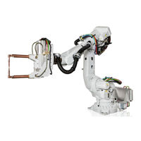
ABB DressPack IRB 6700 Product Manual (240 pages)
Brand:
ABB
| Category:
Robotics
| Size: 7.34 MB
Table of Contents
Table of Contents
5
Overview of this Manual
9
Product Documentation, IRC5
12
How to Read the Product Manual
14
Product Name Principles
15
1 Safety
17
Introduction to Safety Information
17
General Safety Information
18
Introduction to General Safety Information
18
Safety in the Robot System
19
Protective Stop and Emergency Stop
21
Safety Risks
22
Safety Risks During Installation and Service Work on Manipulators
22
CAUTION - Hot Parts May Cause Burns
25
Safety Risks Related to Tools/Work Pieces
26
Safety Risks Related to Pneumatic/Hydraulic Systems
27
Safety Risks During Operational Disturbances
28
Risks Associated with Live Electric Parts
29
Safety Actions
31
Safety Fence Dimensions
31
Fire Extinguishing
32
Emergency Release of the Robot Arm
33
Brake Testing
34
Risk of Disabling Function "Reduced Speed 250 MM/S
35
Enabling Device and Hold-To-Run Functionality
36
Work Inside the Working Range of the Robot
37
Signal Lamp (Optional)
38
Safety Signals and Symbols
39
Safety Signals in the Manual
39
Safety Symbols on Product Labels
41
Safety Related Instructions
47
DANGER - Moving Robots Are Potentially Lethal
47
DANGER - First Test Run May Cause Injury or Damage
48
WARNING - the Brake Release Buttons May be Jammed after Service Work
49
DANGER - Make Sure that the Main Power Has Been Switched off
50
WARNING - the Unit Is Sensitive to ESD
51
WARNING - Safety Risks During Handling of Batteries
53
WARNING - Safety Risks During Work with Gearbox Lubricants (Oil or Grease)
54
2 Installation
57
Introduction
57
Overview
58
Fitting Dresspack on an IRB 6700Inv
59
Fitting the Cable Package Attachments
63
Fitting Attachments of the IRBDP MH3 UE
63
Fitting Attachments of the IRBDP MH3 LI
68
Fitting Attachments of the IRBDP SW6 LE (Lean ID)
71
Fitting Attachments of the IRBDP MH6 UI and IRBDP SW6 UI (Lean ID)
77
Fitting the Process Turning Disc
84
Fitting Dresspack Cable Packages
89
Fitting the Cable Package IRBDP MH3 UE
89
Fitting the Cable Package IRBDP MH3 LI
95
Fitting the Cable Package IRBDP SW6 LE (Lean ID)
102
Fitting the Cable Packages IRBDP MH6 UI and IRBDP SW6 UI (Lean ID)
111
Inspection, Dresspack Lower Arm
120
Inspection, Dresspack Upper Arm
121
Expected Lifetime of the Integrated Dresspack Cable Package
123
Dresspack Adjustments
124
Adjustments of the Cable Package - IRBDP MH3 UE
124
Inspection During Programming and Test-Running
125
Dresspack Arm Load Parameters
127
Dresspack - Arm Load Parameters and Loadid
127
Dresspack Floor
132
Installation of Dresspack Floor
132
Inspection, Dresspack Floor
135
Water & Air Unit
136
Installation of Water and Air Unit
136
Return Water Flow Control
143
Return Water Flow Switch Setting
144
Setting of Air Pressure Switch (Only Applicable to Type S)
146
Setting of Electrical Proportional Valve (Option)
148
3 Maintenance
151
Introduction
151
Maintenance Schedule and Component Life
152
Maintenance Schedule
152
Inspection Activities Spotpack
154
Preventive Inspection of All Cables, Dresspack
154
Preventive Inspection, Dresspack Upper Arm
156
Preventive Inspection of Water and Air Unit
160
Cleaning Activities
162
Cleaning, Dresspack Upper Arm
162
Cleaning, Water and Air Unit
163
4 Repair
165
Introduction
165
Dresspack Cable Package
166
Replacing the Cable Package IRBDP MH3 UE
166
Replacing the Cable Package IRBDP MH3 LI
170
Replacing the Cable Package IRBDP SW6 LE (Lean ID)
176
Replacing the Cable Packages IRBDP MH6 UI and IRBDP SW6 UI (Lean ID)
182
Replacing the Protection Hose IRBDP SW6 UI and IRBDP MH6 UI
188
Water & Air Unit
198
Replacement of Air Supply Circuit
198
Replacement of Water-In Circuit
201
Replacement of Water-Return Circuit
203
Replacement of Air Filter Element
206
5 Decommissioning
209
Environmental Information
209
6 Reference Information
211
Introduction
211
Unit Conversion
212
Screw Joints
213
Weight Specifications
216
Toolkits, Dresspack/Spotpack
217
Lifting Accessories and Lifting Instructions
219
7 Spare Parts
221
Introduction
221
Dresspack Cable Package IRBDP SW6 LE
222
Dresspack Cable Package IRBDP SW6 UI
223
Dresspack Cable Package IRBDP MH3 UI
224
Dresspack Cable Package IRBDP MH6 LI
225
Dresspack Cable Package IRBDP MH6 UI
226
Sub Cables
227
Wear Parts
228
Connection Kits
230
7Th Axis to Base
231
Dresspack Floor
232
Customer Signal/Power
233
Water and Air Unit
234
8 Circuit Diagrams
235
Index
237
Advertisement
Related Products
ABB IRB 6700 Series
ABB IRB 6790
ABB IRB 6700
ABB IRB 6700I
ABB OmniCore IRB 6740
ABB IRB 6730
ABB IRB 6710
ABB OmniCore IRB 6720
ABB IRB 6650S - 200/3.0
ABB IRB 6640 Foundry Prime
ABB Categories
Industrial Equipment
Controller
Measuring Instruments
Battery Charger
DC Drives
More ABB Manuals
Login
Sign In
OR
Sign in with Facebook
Sign in with Google
Upload manual
Upload from disk
Upload from URL