Sony WM-FX661 Service Manual
Radio cassette player
Hide thumbs
Also See for WM-FX661:
- Operating instructions (2 pages) ,
- Operating instructions (2 pages)
Table of Contents
Advertisement
WM-FX661/FX663/FX665
SERVICE MANUAL
Ver 1.1 2002. 01
Sony Corporation
9-924-908-12
2002A1600-1
Personal Audio Company
© 2002.1
Published by Sony Engineering Corporation
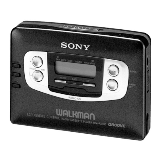
Photo : WM-FX661
RADIO CASSETTE PLAYER
AEP Model
WM-FX661/FX663/FX665
E Model
Chinese Model
WM-FX663/FX665
UK Model
Australian Model
WM-FX665
Canadian Model
WN-FX663
Advertisement
Table of Contents

Related Manuals for Sony WM-FX661


Summary of Contents for Sony WM-FX661
- Page 1 AEP Model WM-FX661/FX663/FX665 Ver 1.1 2002. 01 E Model Chinese Model WM-FX663/FX665 UK Model Australian Model WM-FX665 Canadian Model WN-FX663 Photo : WM-FX661 RADIO CASSETTE PLAYER Sony Corporation 9-924-908-12 2002A1600-1 Personal Audio Company © 2002.1 Published by Sony Engineering Corporation...
-
Page 2: Table Of Contents
CRITIQUES POUR LA SÉCURITÉ DE FONCTIONNEMENT. NE • Never reuse a disconnected chip component. REMPLACER CES COMPOSANTS QUE PAR DES PIÈSES SONY • Notice that the minus side of a tantalum capacitor may be DONT LES NUMÉROS SONT DONNÉS DANS CE MANUEL OU damaged by heat. -
Page 3: General
SECTION 1 GENERAL • LOCATION OF CONTROL 1 OPEN knob 2 PRESET + /AMS FF button 3 PRESET – /AMS REW button 4 TUNING + button !¢ 5 TUNING – button 6 ENTER button 7 ˇ /REPEAT button 8 p /RADIO OFF button 9 MENU button 0 SET button !“... -
Page 4: Disassembly
SECTION 3 DISASSEMBLY Note : Disassemble the unit in the order as shown below. CASE ASSY AUDIO BOARD TUNER BOARD MECHANISM DECK CASSETTE LID ASSY Note : Follow the disassembly procedure in the numerical order given. 3-1. CASE ASSY REMOVAL 4 Screws (M1.4 ×... -
Page 5: Audio Board Removal
3-3. AUDIO BOARD REMOVAL 7 AUDIO board 2 Remove solder 1 Screw (M1.7 × 3) 4 Flexible board 3 Remove solder 3-4. CASSETTE LID ASSY REMOVAL 2 Screw (M1.4 × 2) 5 Cassette lid assy 3 Screw (M1.4 × 2) 1 OPEN button —... -
Page 6: Mechanism Deck Removal
3-5. MECHANISM DECK REMOVAL 4 Reel ornament 5 Mechanism deck — 6 —... -
Page 7: Mechanical Adjustment
SECTION 4 SECTION 5 MECHANICAL ADJUSTMENT ELECTRICAL ADJUSTMENT PRECAUTION PRECAUTION Clean the following parts with a denatured-alcahol-moistened Specified voltage : 1.3V sweb : Switch position Playback head Pinch roller DOLBY NR switch : OFF Rubber belt Capstan AVLS switch : OFF Demagnetize the playback head using a demagnetizer. - Page 8 TUNER SECTION FM VCO Adjustment Procedure : [AM] FM RF signal BAND switch : AM generator AM RF signal 0.01µF generator to ANT (TP1) Put the lead-wire antenna close to the set. Carrier frequency : 98MHz Modulation : No moduration Output level : 0.1V (100dB) 30% amplitude modulation...
-
Page 9: Diagrams
SECTION 6 DIAGRAMS 6-2. IC PIN FUNCTION DESCRIPTION 6-1. BLOCK DIAGRAM • IC1 TC9326F-051 Pin No. Function Pin Name Circuit Description Remarks Pin No. Function Pin Name Circuit Description Remarks AUDIO VCC1 POWER AMP DATA 1 to 3 COM 1 to 3 COM 1 to 3 —... - Page 14 MEMO • IC BLOCK DIAGRAMS IC3 TA7371AF-EL (TUNER SECTION) IC301 TA2072AF (AUDIO SECTION) IC601 MM1279XVBE (AUDIO SECTION) IC7 TA-2022AFN-EL (TUNER SECTION) — 27 — — 28 —...
-
Page 15: Exploded Views
SECTION 7 EXPLODED VIEWS NOTE: • -XX, -X mean standardized parts, so they may • The mechanical parts with no reference number • Abbreviation have some differences from the original one. in the exploded views are not supplied. : Central and South CND : Canadian model •... -
Page 16: Audio, Tuner Board Section
7-2. AUDIO, TUNER BOARD SECTION S901 MT-WMEX550-125 Ref. No. Part No. Description Remarks Ref. No. Part No. Description Remarks 3-375-114-41 SCREW (M1.7 × 3) 3-937-993-61 LID, BATTERY CASE (SILVER)(FX665) A-3021-086-A TUNER BOARD, COMPLETE 3-937-993-71 LID, BATTERY CASE (SILVER)(FX661) A-3061-729-A AUDIO BOARD, COMPLETE (FRENCH) X-3373-190-1 TERMINAL BOARD ASSY, BATTERY A-3061-731-A AUDIO BOARD, COMPLETE (EXCEPT FRENCH) 3-009-690-01 TERMINAL BOARD, BATTERY... -
Page 17: Mechanism Section (Mt-Wmex550-125)
7-3. MECHANISM SECTION (MT-WMEX550-125) PM901 M901 HP301 not supplied Ref. No. Part No. Description Remarks Ref. No. Part No. Description Remarks X-3374-440-1 CHASSIS ASSY (J2) 3-011-277-01 COVER (B) (Y), MD 3-007-455-01 SPRING (R), TORSION 3-019-716-01 SCREW (M1.4), P LOCK ACE 3-007-458-01 SPRING (H/B), TENSION X-3372-850-1 PINCH LEVER (N) ASSY 3-007-456-01 SPRING (N), TORSION... -
Page 18: Electrical Parts List
SECTION 8 TUNER ELECTRICAL PARTS LIST NOTE: • Due to standardization, replacements in the • RESISTORS When indicating parts by reference number, parts list may be different from the parts All resistors are in ohms. please include the board naame. specified in the diagrams or the components METAL: metal-film resistor The components identified by mark ! or... - Page 19 Ver 1.1 2002.01 TUNER Ref. No. Part No. Description Remarks Ref. No. Part No. Description Remarks < DIODE > < RESISTOR > 8-719-053-30 DIODE MA2S357-(TX). SO 1-216-825-11 METAL CHIP 2.2K 1/16W 8-719-053-30 DIODE MA2S357-(TX). SO 1-216-853-11 METAL CHIP 470K 1/16W 8-719-055-61 DIODE HVR100-9TRU 1-216-853-11 METAL CHIP 470K...
- Page 20 TUNER AUDIO Ref. No. Part No. Description Remarks Ref. No. Part No. Description Remarks 1-216-833-11 METAL CHIP 1/16W C111 1-107-823-11 CERAMIC CHIP 0.47uF 1-216-841-11 METAL CHIP 1/16W C112 1-115-156-11 CERAMIC CHIP 1-216-833-11 METAL CHIP 1/16W C113 1-115-156-11 CERAMIC CHIP 1-216-829-11 METAL CHIP 4.7K 1/16W C114...
- Page 21 AUDIO Ref. No. Part No. Description Remarks Ref. No. Part No. Description Remarks < CONNECTOR > R112 1-216-824-11 METAL CHIP 1.8K 1/16W R113 1-216-809-11 METAL CHIP 1/16W CN301 1-766-336-21 CONNECTOR, FFC/FPC 6P R114 1-216-840-11 METAL CHIP 1/16W CN701 1-779-079-11 CONNECTOR, BOARD TO BOARD R115 1-216-849-11 METAL CHIP 220K...
- Page 22 WM-FX661/FX663/FX665 AUDIO Ref. No. Part No. Description Remarks Ref. No. Part No. Description Remarks < COMPOSITION CIRCUIT BLOCK > 1-528-713-11 BATTERY CHARGER (BC-7DC)(FX663:CND) 1-528-744-21 BATTERY CHARGER (BC-7DY) RB301 1-233-872-21 RES, NETWORK (CHIP TYPE)(3216) (FX661/FX663:AEP,IT,FR,EA/FX665:AEP,IT,FR,EA,5E) RB601 1-233-873-21 RES, NETWORK (CHIP TYPE)(3216)
- Page 23 WM-FX661/FX663/FX665 Printing Method for Large Sized Documents Such As Circuit Diagrams Printing the page that exceeds A4-size two pages (or letter size) is possible by specifying the print range. (Acrobat Reader Version 4.0 or later) 1. The enlarged print is made, if a smaller range than A4 size is specified and the A4 size is selected as a print paper.
-
Page 24: Revision History
WM-FX661/FX663/FX665 REVISION HISTORY Clicking the version allows you to jump to the revised page. Also, clicking the version at the upper right on the revised page allows you to jump to the next revised page. Ver. Date Description of Revision 1998.05...