
Related Manuals for Whirlpool W5WCE065XW0

Summary of Contents for Whirlpool W5WCE065XW0
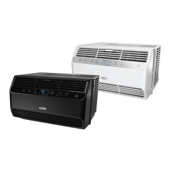
- Page 1 R-113 Technical Education 2011 Room Air Conditioners Models W5WCE065XW0 W7WCC065XB0 W5WCE085XW0 W5WCE105XW0 W5WCE128XW0 Prepared by: WHIRLPOOL CONSUMER CARE Job Aid W10411218...
-
Page 2: Goals And Objectives
This Room Air Conditioner Guide (W10411218), provides the In-Home Service Professional with informa- tion on how to access the controls, motors and fans on Whirlpool’s 2011 room air conditioners. For specific information on the model being serviced, refer to the information supplied with the air con- ditioner. -
Page 3: Table Of Contents
WHIRLPOOL ROOM AIR MODELS NUMBER NOMENCLATURE 2011 . . . . . . . . . . . . . . . . . - Page 4 CONTENTS (continued) Page DIAGNOSTICS AND TROUBLESHOOTING . . . . . . . . . . . . . . . . . . . . . . . . . . . . . . . . . . . . . . . . . . . . . . . . . 5-1 Voltage Measurement Safety Information .
-
Page 5: Safety First
SAFETY FIRST NOTICE TO THE TECHNICIAN It is the responsibility of the Service Technician to comply with all EPA Regulations and Standards and possesses all necessary State and Federal licenses when servicing air conditioners. Federal regulations and Standards can be found on the United States Government EPA Web Site. State Regulations and Standards and licensing requirements, in most cases, can be found on the State Government Web Site . -
Page 7: Specifications
Specifications W5WCE065XW0 W7WCC065XB0 W5WCE085XW0 W5WCE105XW0 W5WCE128XW0 6300 6300 8000 10000 12000 BTU Rating 10.9 10.7 115 VAC 115 VAC 115 VAC 115 VAC 115 VAC Voltage 60 HZ 60 HZ 60 HZ 60 HZ 60 HZ Frequency 7.1 A 7.1 A 9.7 A... -
Page 8: Installation Information
Installation Information NOTE: Cabinet louvers must not be obstructed. Air must be able NOTE: Cabinet louvers must not be obstructed. Air must be able Tools and Parts—All Models to pass freely through the cabinet louvers. Tools and Parts—All Models to pass freely through the cabinet louvers. NOTE: Cabinet louvers must not be obstructed. -
Page 9: Electrical Requirements
Do not remove ground prong. Do not use an adapter. Electrical Requirements—All Models Do not use an extension cord. Copies of the standards listed may be obtained from: WARNING Failure to follow these instructions can result in death, National Fire Protection Association Electrical Requirements (All Models) 1 Batterymarch Park fire, or electrical shock. -
Page 10: Prepare Air Conditioner For Installation
Installation Requirements (continued) NOTES: NOTES: NOTES: The Reset button must be pushed in for proper operation. The Reset button must be pushed in for proper operation. The Reset button must be pushed in for proper operation. The power supply cord must be replaced if it fails to trip when The power supply cord must be replaced if it fails to trip when The power supply cord must be replaced if it fails to trip when the test button is pressed or fails to reset. -
Page 11: Prepare Window For Installation
Installation Requirements (continued) Do not block the air intake or discharge louvers in the front 3. Slide the side curtain frame into the top channel on the top of panel. the air conditioner and the track on the bottom of the air conditioner. -
Page 12: Complete Installation
Installation Requirements (continued) Complete Installation Complete Installation Complete Installation 1. Insert the foam seal without adhesive behind the top of the 1. Insert the foam seal without adhesive behind the top of the lower window sash and against the glass of the upper 1. -
Page 13: Product Operation
Use two or more people to move and install air conditioner. SAVE THESE INSTRUCTIONS PRODUCT REGISTRATION Thank you for purchasing a Whirlpool window air conditioner. In Quality Assurance—Call within 10 days; the sooner we have order to better serve you, please take a moment to register your your information, the better we are able to help you. -
Page 14: Starting Your Air Conditioner
Operation (continued) Operating your air conditioner properly helps you to obtain the Do not try to operate your air conditioner in the Cool. Eco (on best possible results. some models) or Overnight (on some models) mode when outside temperature is below 65°F (18°C). The inside This section explains proper air conditioner operation. -
Page 15: Mode
(18°C). The inside evaporator coil will freeze up, and the air This section explains proper air conditioner operation. Operating your air conditioner properly helps you to obtain the Do not try to operate your air conditioner in the Cool, Eco or conditioner will not operate properly. - Page 16 Operation (continued) Fan Speed 1. Press FAN SPEED until you see the Bar LED display for the NOTES desired setting . Auto fan speed and Temperature cannot be selected in Fan Only mode. 2. Choose High, Med, Low or Auto. In Eco and Cool modes, Auto fan speed is selected Low—Low cooling—1 bar and “1”...
-
Page 17: Timed On Off
Operation (continued) Timed On Off Timed On Off The Timed On Off function allows the air conditioner to be set to 6. Press TIMED ON again while the actual time that the unit will turn on or off any time during the day or night, or to turn on or off turn off... -
Page 18: Using The Remote Control
Operation (continued) Using the Remote Control Using the Remote Control Storing the Remote Control Temp NOTE: NOTE: Store the remote control by placing the back side, containing a NOTE: Power Mode Fan Speed Power SENSE ® Power NOTE: Power Mode Press MODE to choose Cool, Eco, Overnight or Fan. -
Page 19: Fan Speed
(on some models) or Fan Only. for an annual checkup. Remember … the cost of this service call is your responsibility. Cleaning the Air Filter Operation (continued) Mode Sixth Sense Operation Fan Speed 2 weeks to see whether it needs cleaning. NOTES: NOTE: Sense... -
Page 20: Air Conditioner Care
A. Tab Air Conditioner Care AIR CONDITIONER CARE Air Conditioner Care 3. Remove the filter from the grille by lifting to release the 4. Use a vacuum cleaner to clean air filter. If the air filter is very slotted tabs on the top and bottom of the grille. dirty, wash it in warm water with a mild detergent. -
Page 21: Component Access
Component Access This section instructs you on how to service each component inside the 2011 Room Air Conditioners. Electrical Shock Hazard Disconnect power before servicing. Replace all parts and panels before operating. Failure to do so can result in death or electric shock. -
Page 22: Removing The Front Panel
Component Access Removing the Front Panel Remove the (2) screws (one on each side) of the front panel, (see figure 3). Electrical Shock Hazard Disconnect power before servicing. Replace all parts and panels before operating. Screws (one on each side) Failure to do so can result in death or electric shock. -
Page 23: Removing The Cabinet
Component Access (continued) Removing the Cabinet Electrical Shock Hazard Disconnect power before servicing. Replace all parts and panels before operating. Figure 3 Failure to do so can result in death or electric shock. Remove upper and middle Styrofoam blower housing. Using a utility knife cut the grey foam Unplug air conditioneror disconnect power. -
Page 24: Removing The Control And User Interface
Component Access (continued) Removing the Control and User Interface Remove connectors and replace board, (see figure 3). Electrical Shock Hazard Disconnect power before servicing. Replace all parts and panels before operating. Failure to do so can result in death or Figure 3 electric shock. -
Page 25: Removing The Fan Assembly
Component Access (continued) Removing the Fan Assembly Remove 2 screws on the left side of the condenser, (see figure 3). Electrical Shock Hazard Screws Disconnect power before servicing. Replace all parts and panels before operating. Failure to do so can result in death or electric shock. - Page 26 Component Access (continued) Removing the Fan Assembly (continued) To remove the Condenser blade: Remove the nut and washers, be sure to note the orientation of the condenser blade hub for correct reassembly. Left hand thread, turn clockwise to remove. (see figure 7). Electrical Shock Hazard Disconnect power before servicing.
- Page 27 Notes...
-
Page 28: Diagnostics And Troubleshooting
FOR SERVICE TECHNICIAN’S USE ONLY FOR SERVICE TECHNICIANS ONLY Tech Sheet Do not discard Diagnostics and Troubleshooting DANGER WARNING FOR SERVICE TECHNICIAN’S USE ONLY Tech Sheet Do not discard DANGER WARNING Electrical Shock Hazard Electrical Shock Hazard Electrical Shock Hazard Electrical Shock Hazard Only authorized technicians should Disconnect power before servicing. -
Page 29: Troubleshooting Chart
FOR SERVICE TECHNICIANS ONLY Diagnostics and Troubleshooting (continued) TROUBLESHOOTING CHART PROBLEM PROBABLE CAUSE CORRECTION 1. Unit does not run. 1a.No power to unit. 1a. Check for power at receptacle, good plug contact, fuses of correct size and time delay types. (Have customer contact electrician if no power is avail- able at receptacle.) 1b. - Page 30 Diagnostics and Troubleshooting (continued) FOR SERVICE TECHNICIANS ONLY PROBLEM PROBABLE CAUSE CORRECTION 6. Compressor stops and 6a.Incorrect voltage. 6a.Check for proper voltage. starts. Too short run- 6b.Temperature control set too warm. 6b.Instruct customer. ning time. 6c. Failed thermistor or thermostat. 6c.
- Page 31 FOR SERVICE TECHNICIANS ONLY Diagnostics and Troubleshooting (continued) PROBLEM PROBABLE CAUSE CORRECTION 9. Evaporator frosting 9a. Low outside air temperature (below 9a.Instruct customer that opera- 65°F). tion at ambient temperatures below 65°F is not considered a normal requirement of the unit. NOTE: 90% frosting of Adjust the controls to a warmer evaporator is normal un-...
-
Page 32: Refrigerant System
Diagrams Refrigerant System CENTRIFUGAL AXIAL FAN OR CROSS FAN COOLED AIR HOT DISCHARGED AIR COMPRESSOR OUTDOOR COILS INDOOR COILS CAPILLARY REFRIGERANT FLOW DIRECTION All Models use R-410A refrigerant. R-410A operates at higher pressures and temperatures than R-22 units and requires dedicated sealed system equipment. Note: Do not attempt sealed system entry or service unless you have been trained on servicing R410-A systems and have the proper equipment. -
Page 33: Schematic Diagram
Diagrams (continued) Schematic Diagram Symbol Color symbol Symbol Color symbol WHITE BROWN YELLOW BLUE BLACK YEGN YELLOW GREEN COMPRESSOR COMP PROTECTIVE EARTH BK(BN) TRANSFORMER R00M TEMP. SENSOR WH(BU) GN(YEGN) TUBE TEMP. POWER SENSOR ROOM TR-IN TR-OUT G(PE) K201 OVERLOAD COMP. PROTECTOR AP1 PRINTED CIRCUIT BOARD...