Advertisement
SERVICE MANUAL
Ver 1.0 2001.03
System
Type
Active Subwoofer (magnetically shielded design)
Speaker unit
Woofer: 20 cm dia. (8 in.), cone type
Amplifier section
Continuous RMS output :
Canadian model (0.8%) 50W
European model (DIN) 50 W
Other models (0.8%) 50 W
Reproduction frequency range
28 Hz – 200 Hz
Inputs
Input jacks
LINE IN: input pin jack
Sony Corporation
9-873-847-11
2001C0900-1
Audio Entertainment Group
© 2001. 3
General Engineering Dept.
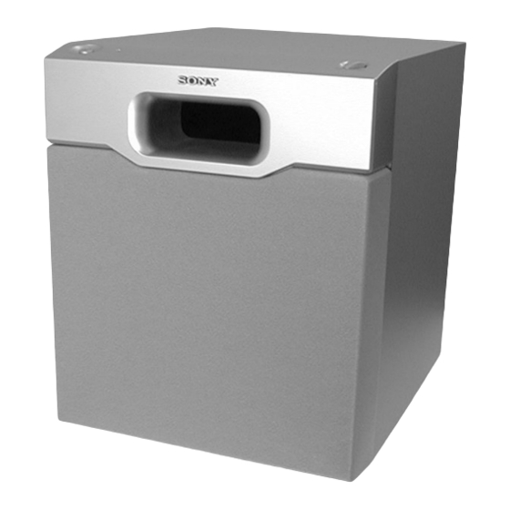
SA-WMSP1
SPECIFICATION
General
Power requirements
Canadian model: 120 V AC, 60 Hz
European model: 230 V AC, 50/60 Hz
Power consumption
50 W
Dimensions
Approx. 270 x 325 x 385 mm
(10
3
/
x 12
7
/
x 15
4
8
Mass
10 kg (22 lb 1oz)
Design and specifications are subject to change
without notice.
US Model
Canadian Model
AEP Model
UK Model
E Model
Australian Model
Chinese Model
1
/
in.) (w/h/d)
4
ACTIVE SUBWOOFER
1
Advertisement
Table of Contents

Related Manuals for Sony SA-WMSP1


Summary of Contents for Sony SA-WMSP1
- Page 1 SA-WMSP1 SERVICE MANUAL US Model Canadian Model Ver 1.0 2001.03 AEP Model UK Model E Model Australian Model Chinese Model SPECIFICATION System General Type Power requirements Active Subwoofer (magnetically shielded design) Canadian model: 120 V AC, 60 Hz European model: 230 V AC, 50/60 Hz Speaker unit Woofer: 20 cm dia.
-
Page 2: Table Of Contents
CRITIQUES POUR LA SÉCURITÉ DE FONCTIONNEMENT. NE COMPONENTS WITH SONY PARTS WHOSE PART NUMBERS REMPLACER CES COMPOSANTS QUE PAR DES PIÈSES SONY APPEAR AS SHOWN IN THIS MANUAL OR IN SUPPLEMENTS DONT LES NUMÉROS SONT DONNÉS DANS CE MANUEL OU PUBLISHED BY SONY. -
Page 3: General
SA-WMSP1 SECTION 1 SECTION 2 GENERAL DIAGRAMS • Location of controls THIS NOTE IS COMMON FOR PRINTED WIRING BOARDS AND SCHEMATIC DIAGRAMS. – Top view (a part) – (In addition to this, the necessary note is printed in each block.) For printed wiring boards. -
Page 4: Printed Wiring Board
SA-WMSP1 2-2. PRINTED WIRING BOARD • See page 3 for Circuit Boards Location. • Semiconductor Location Ref. No. Location D301 D302 D303 D304 D401 D402 D403 D404 IC101 Q301 Q302 Q303 Q304 Q401... -
Page 5: Schematic Diagram
SA-WMSP1 2-3. SCHEMATIC DIAGRAM... -
Page 6: Exploded View
SA-WMSP1 SENTION 3 EXPLODED VIEWS NOTE: 3-2. AMP SECTION • -XX and -X mean standardized parts, so they • Items marked “*” are not stocked since they The components identified by mark 0 or dotted line with mark may have some difference from the original are seldom required for routine service. -
Page 7: Electrical Parts List
SA-WMSP1 SECTION 4 CONTROL MAIN ELECTRICAL PARTS LIST NOTE: Ref. No. Part No. Description Remarks Ref. No. Part No. Description Remarks • Due to standardization, replacements in the • COILS When indicating parts by reference number, parts list may be different from the parts uH: µH... - Page 8 SA-WMSP1 MAIN POWER IC SWITCH Ref. No. Part No. Description Remarks Ref. No. Part No. Description Remarks J103 1-793-446-11 JACK, PIN 1P (LINE) 1-680-717-13 POWER IC BOARD (US,MX,SP,CND,AEP,UK,AUS) *************** < TRANSISTOR > < CAPACITOR > Q301 8-729-029-86 TRANSISTOR DTC124ESA C302...
- Page 9 SA-WMSP1 MEMO Ref. No. Part No. Description Remarks Ref. No. Part No. Description Remarks...
- Page 10 SA-WMSP1 Ref. No. REVISION HISTORY Part No. Description Remarks Ref. No. Part No. Description Remarks Clicking the version allows you to jump to the revised page. Also, clicking the version at the upper right on the revised page allows you to jump to the next revised page.