Sony PDW-F800 Operation Manual
Professional disc camcorder
Hide thumbs
Also See for PDW-F800:
- Operation manual (318 pages) ,
- Brochure & specs (4 pages) ,
- Maintenance manual (300 pages)
Table of Contents
Advertisement
Quick Links
(1)
* 3 - 2 9 7 - 5 1 7 - 1 2 *
Sony Corporation
PDW-F800
PDW-700
(CE)
3-297-517-12 (1)
Printed on recycled paper.
Printed in Japan
2009.05 13
© 2008
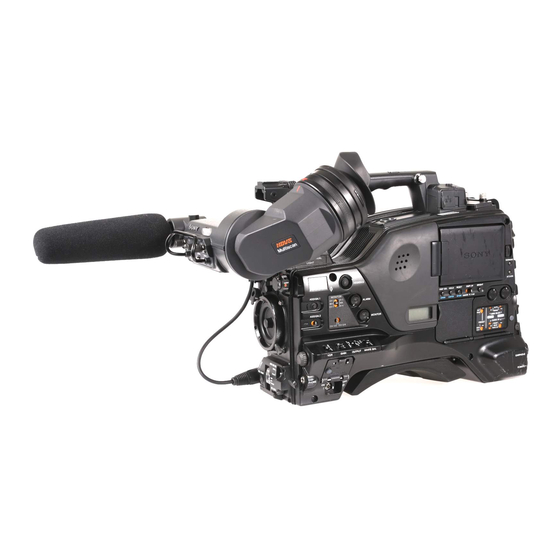
PROFESSIONAL DISC CAMCORDER
PDW-F800
PDW-700
The supplied CD-ROM includes operation manuals for the
PDW-F800/700 Professional Disc Camcorder (English, Japanese,
French, German, Italian, Spanish and Chinese versions) in PDF
format.
For more details, see "Using the CD-ROM manual" on page 12.
OPERATION MANUAL [English]
1st Edition (Revised 3)
(1)
* 3 - 2 9 7 - 5 1 7 - 1 2 *
Advertisement
Table of Contents

Related Manuals for Sony PDW-F800


Summary of Contents for Sony PDW-F800
- Page 1 PROFESSIONAL DISC CAMCORDER PDW-F800 PDW-700 The supplied CD-ROM includes operation manuals for the PDW-F800/700 Professional Disc Camcorder (English, Japanese, French, German, Italian, Spanish and Chinese versions) in PDF format. For more details, see “Using the CD-ROM manual” on page 12.
- Page 2 This label is located WARNING inside the outside panel of the unit. To reduce the risk of fire or electric shock, do not expose this apparatus to Denna etikett finns på rain or moisture. apparatens ovansida. To avoid electrical shock, do not open the cabinet.
- Page 3 1-800-222-7669 or http://www.sony.com/ (residential), E2 (commercial and light industrial), E3 (urban outdoors), E4 (controlled EMC environment, ex. TV studio). The manufacturer of this product is Sony Corporation, 1-7-1 Konan, Minato-ku, Tokyo, Japan. The Authorized Representative for EMC and product safety is Sony Deutschland GmbH,...
- Page 4 : E1 (résidentiel), E2 (commercial et industrie légère), E3 (urbain extérieur) et E4 (environnement EMC contrôlé, ex. studio de télévision). Le fabricant de ce produit est Sony Corporation, 1-7-1 Konan, Minato-ku, Tokyo, Japon. Le représentant autorisé pour EMC et la sécurité...
- Page 5 Freien) und E4 (kontrollierter EMV-Bereich, der Außenabdeckung z.B. Fernsehstudio). des Geräts. Der Hersteller dieses Produkts ist Sony Corporation, 1-7-1 Konan, Minato-ku, Tokyo, Japan. Der autorisierte Repräsentant für EMV und Produktsicherheit ist Sony Deutschland GmbH, Hedelfinger Strasse 61, 70327 Stuttgart, Deutschland.
-
Page 6: Table Of Contents
Table of Contents Foreword ....................12 Before use..................12 Marks for model-specific functions ..........12 Using the CD-ROM manual............12 Chapter 1 : Overview Features ...................... 13 Locations and Functions of Parts and Controls........16 Power supply................... 16 Accessory attachments ..............17 Operating and connectors section ........... - Page 7 Tripod Mounting ..................53 Connecting a Video Light ................. 54 Using the Shoulder Strap ................55 Adjusting the Shoulder Pad Position ............56 Connecting the Remote Control Unit ............56 Chapter 3 : Adjustments and Settings for Shooting Setting the Recording Format ..............59 Setting the system frequency ............
- Page 8 Playing back the recorded clip ............86 Deleting the recorded clip ............... 87 Using the Focus Assist function............88 Advanced Operations for Shooting ............89 Recording essence marks ..............89 Setting clip flags with switches............89 Setting the thumbnail image at recording time ....... 90 Starting a shoot with a few seconds of pre-stored picture data (Picture Cache function).................
- Page 9 Using planning metadata............... 138 Checking user-defined essence marks .......... 139 Formatting discs ................140 Displaying disc and clip properties in a web browser....140 Transferring clips (Direct FTP function) ..........143 Preparations for clip transfers ............144 Uploading clips ................144 Downloading clips ................
- Page 10 Selecting the lens file ..............215 Setting the UMID data ..............215 Chapter 7 : Saving and Loading User Setting Data Handling the “Memory Stick”..............218 Saving and Recalling User Files ............. 219 Saving user menu data to the “Memory Stick”......219 Loading saved data from a “Memory Stick”.........
- Page 11 Testing the VDR ................245 Maintenance ..................... 247 Cleaning the viewfinder ..............247 Note about the battery terminal............. 248 Operation Warnings ................249 Appendix Important Notes on Operation ............... 257 Specifications.................... 259 General ..................259 Video camera section ..............259 Optical disc drive section ..............
-
Page 12: Foreword
PDW-F800 or only by the PDW-700 are If you have lost or damaged the CD-ROM, you can indicated by the following marks. purchase a new one to replace it. Contact a Sony service representative. [F800]: PDW-F800 [700]: PDW-700... -
Page 13: Chapter 1 : Overview
-inch full-HD “PowerHAD FX” 1) The PDW-700 requires installation of the optional CCDs CBKZ-FC01 23.98P Record and Playback Software and a verification key. For details, contact a Sony • IT (Interline Transfer) -inch progressive service representative. image sensors with 2.2 million pixels, for full 2) When the current recording format is 720/59.94P, you... - Page 14 1) The PDW-700 requires installation of the optional [F800] CBKZ-MD01 SD Record and Playback Software and Two optical filters a verification key. For details, contact a Sony service The unit is equipped with separate CC filters and representative. ND filters. Two filters can be used simultaneously.
- Page 15 film camera. Unlike low-speed or high-speed 3.5-inch color LCD monitor playback of normally shot video, this provides a The 3.5-inch color LCD monitor displays easy- smooth slow-motion effect, or action speeded up to-read audio meters, menus, disc and battery beyond actual speed. capacity indications, and thumbnails of clips 1) This function is available when the recording format is stored on disc.
-
Page 16: Locations And Functions Of Parts And Controls
If the beginning of the recording is important, you should set this switch to MANUAL. • To ensure proper operation of the video light, Sony recommends the use of the BP-GL95/L80S Battery Pack with the camcorder. -
Page 17: Accessory Attachments
VF (viewfinder) connector (20-pin) Accessory attachments Connect an optional viewfinder. Consult a Sony representative for information about available viewfinders. g Lens mount securing rubber After locking the lens in position using the lens locking lever, fit this rubber over the lower of the two projections. -
Page 18: Operating And Connectors Section
[F800] The PDW-F800 is equipped with two switchable filters. You can switch between four electrical CC filters and four ND filters. Locations and Functions of Parts and Controls... - Page 19 d MENU knob FILTER selector CC filter Changes the page selection or a setting within the (outer knob) setting menu. Cross filter For details about how to use the MENU knob, see 3200K “Menu Operations” on page 195. 4300K e EARPHONE jack (monaural, 6300K minijack) a) A type of special effect filter.
- Page 20 [700] Right side (near the front) b COLOR TEMP. (color temperature) button 2 3 4 Press to light the button and change the color temperature for shooting. You can use this as an ASSIGN (assignable) switch (see page 211) c ALARM (alarm tone volume adjustment) knob Controls the volume of the warning tone that is output via the built-in speaker or optional...
-
Page 21: Gain Selector
a) By connecting stereo headphones to the EARPHONE • Shooting a subject indoors, against a background jack on the rear of the unit, you can hear the audio in through a window stereo. (On the AUDIO-1 page of the • Any high contrast scene MAINTENANCE menu, HEADPHONE OUT must i WHITE BAL (white balance memory) be set to STEREO.) -
Page 22: Lcd Monitor
k MENU ON/OFF switch For details about “Memory Stick”, see “Handling the “Memory Stick”” on page 218. To use this switch, open the cover. This switch is used to display the menu on the n Cover viewfinder screen or the test signal screen. Closing the cover automatically sets this switch to Right side (near the rear) OFF. -
Page 23: Warning Indicator
For details, see “Status Display on the LCD monitor approximately four times normal playback speed, and monochrome LCD” on page 24. press the F REV button or F FWD button during playback. c WARNING indicator At this time the PLAY indicator and F REV or F Lights up or flashes when an abnormality occurs FWD indicator light. -
Page 24: Display Switch
Hold down the SHIFT button and press this information for the user such as scene number, shooting place, etc. button to step back through the division process. For details, see “Setting the Time Data” on page 76. For details of the expand function, see page 120. p HOLD (display hold)/CHAPTER This button returns to the previous screen when pressed during thumbnail display. -
Page 25: Video Format
If NTSC AREA is selected Indication Field or frame Scan mode rate 59.9i 59.94 fields per Interlace O V E R HD422 50 5 9 . 9 i 2 4 b i t second 1080 N D F E X T - L K H O L D 01 . -
Page 26: Time Counter Display
HOLD: Appears when the internal timecode generator is stopped. g Time counter display Switches displays of time counter, timecode, and user bits, depending on the position of the DISPLAY switch. When the HOLD/CHAPTER button is pressed to hold the timecode value, the timecode is displayed in the format shown below. -
Page 27: Remaining Disc Capacity Indicator
i Remaining disc capacity indicator Indication Remaining recording time DISC E [x x x x x x x] B More than 30 minutes DISC E [x x x x x x x] B 25 to 30 minutes DISC E [x x x x x x] B 20 to 25 minutes DISC E [x x x x... -
Page 28: D Menu Button
e F-RUN/SET/R-RUN (free run/set/ GUI screen operations section and audio control section recording run) switch Selects the operating mode of the internal timecode generator. The operating mode is set as 2 3 4 5 explained below, depending on the position of the switch. -
Page 29: Lid Of The Disc Compartment
k AUDIO SELECT CH-1/CH-2 (audio Left side and upper section channel 1/2 adjustment method selection) switches Select the audio level adjustment method for each of audio channels 1 and 2. AUTO: Automatic adjustment MANUAL: Manual adjustment l AUDIO IN CH-1/CH-2/CH-3/CH-4 (audio channel 1/2/3/4 input selection) switches AUDIO IN CH-1/CH-2 switches... -
Page 30: Usb Connector
g TC OUT (timecode output) connector Use the GENLOCK page of the MAINTENANCE menu to adjust the genlock (BNC type) H-phase (phase of horizontal sync signal). To lock the timecode of an external VTR to the Available reference signals vary depending on timecode of this unit, connect this connector to the current system frequency as shown in the the external VTR’s timecode input connector. - Page 31 same time. Plugging an earphone into the jack Device Enables automatically cuts off the built-in speaker. Windows USB Text input wth the on-screen You can select monaural or stereo on the AUDIO- keyboard or mouse software keyboard (see page 1 page of the MAINTENANCE menu. 126) f LINE / AES/EBU / MIC selectors USB flash drive...
-
Page 32: Hdvf-20A Viewfinder (Optional)
depending on the menu settings, and you can HDVF-20A viewfinder (optional) view them on the monitor screen. k AUDIO IN CH1/CH2 (audio channel-1 and channel-2 input) connectors (XLR type, 3-pin, female) These are audio input connectors for channels 1 and 2 to which you can connect audio equipment or a microphone. -
Page 33: Status Display On The Viewfinder Screen
n Viewfinder cable This indicator also flashes to indicate warnings, in the same manner as the camera operator tally o Microphone holder indicator and the REC indicator in the viewfinder. h PEAKING control Status display on the viewfinder Turning this control clockwise adjusts the picture screen sharpness, and makes focusing easier. -
Page 34: Viewfinder Screen
R and B, in the range 0.0 K to 99.9 K (in steps of 0.1 K). The +/– signs may be displayed 2) For the PDW-F800, when SHUTTER SELECT on the SHUTTER SELECT page of the MAINTENANCE depending on the OFFSET WHT setting (see menu is set to DEGREE, the standard setting is page 214). -
Page 35: System Frequency And Frame Rate
+: The value of OFFSET WHT is greater than segment reception level indicators for each of the 3200K. channels (1 or 2 channels) that can be used by the –: The value of OFFSET WHT is less than tuner. The indications are as follows. 3200K. -
Page 36: Electric Color Temperature Filter
l Memory symbol and remaining SNGL: Appears when SINGLE CLIP MODE in the CAM CONFIG 1 page of the memory capacity MAINTENANCE menu is set to “ON”, and When a USB flash drive is connected to the the unit is searching or playing a clip (see enabled USB connector, a memory symbol page 86). -
Page 37: Shutter Speed
f White balance memory Indicates the currently selected white balance automatic adjustment memory. A: Displayed when the WHITE BAL switch is set -12 -8 (dB) to A. B: Displayed when the WHITE BAL switch is set 1 Audio channel 1 level indicator 2 Audio channel 2 level indicator to B. -
Page 38: Remaining Clips Display
m Remaining clips display Displays the remaining number of clips that can be recorded. The display flashes once per second when the number of remaining clips is less than n Iris setting/auto iris override Indicates the F value (iris setting) of the lens. Auto iris override is shown by an indicator made up of two segments each on the upper and lower sides. -
Page 39: Chapter 2 : Preparations
A warm battery pack may not be able to be fully recharged. To attach the battery pack For safety, use only the Sony battery packs and AC adaptors listed below. Press the battery pack against the back • BP-GL95/GL65/L60S/L80S Lithium-ion... -
Page 40: Using Ac Power
To an AC outlet 1 “LOCK” arrow 2 Matching line on the camcorder Note If the battery pack is not attached correctly, the terminal may be damaged. To detach the battery pack Holding the release button in, pull the battery pack up. -
Page 41: Attaching The Viewfinder
VF connector. If the coupling is loose, noise may appear on the video or the tally light may not operate properly. For more information about the connection of the viewfinder and camcorder, contact a Sony service representative. 1 Loosen the viewfinder left-to-right Detaching the viewfinder... -
Page 42: Moving The Viewfinder Shoe Up
Viewfinder left-to-right positioning ring Handle front cover Bolt with hexagonal hole Viewfinder front-to-back positioning knob Viewfinder slide assembly Moving the viewfinder shoe up Attach the handle front cover with the bottom edge up. Loosen the front-to-back viewfinder positioning levers and the front-to-back viewfinder positioning knobs, and then pull the viewfinder slide assembly forward. -
Page 43: Using The Bkw-401 Viewfinder Rotation Bracket
Adjust position so that arm Using the BKW-401 Viewfinder does not touch handle Rotation Bracket By fitting a BKW-401 Viewfinder Rotation Bracket (not supplied), you can rotate the viewfinder out of the way so that your right leg does not hit the viewfinder while you are carrying the camcorder. -
Page 44: Adjusting The Viewfinder Focus And Screen
When the eyecup is worn out, replace it with a new one. For details of a replacement eyecup, contact a Sony service representative. Adjusting the viewfinder focus and screen To adjust the viewfinder focus Turn the diopter adjustment ring until the viewfinder image is sharpest. -
Page 45: Setting The Area Of Use
Turn the MENU knob to display the Setting the Area of Use desired area of use. Setting Area of use NTSC(J)AREA NTSC area (Japan) NTSC AREA NTSC area (for areas other than Japan) PAL AREA PAL area When using the unit for the first time a) The composite signal output from this unit is an The area of use is not factory preset. -
Page 46: Setting The Date/Time Of The Internal Clock
Turn the MENU knob to display the Setting the Date/Time of desired value, and press the MENU knob. the Internal Clock z changes to and ? changes to z. To continue the remaining settings, repeat steps 3 and 4. You can set or change the date and time of the When you finish settings, turn the internal clock. -
Page 47: Mounting The Lens
securing rubber be put on the lens locking lever as Mounting the Lens illustrated above. Connect the lens cable to the LENS connector. Secure the lens cable with the cable clamps. First power off the camcorder, and then mount the lens using the following procedure. -
Page 48: Adjusting The Flange Focal Length
Repeat steps 4 to 7 until the chart stays Adjusting the Flange in focus all the way from wide angle to telephoto. Focal Length Tighten the F.f or F.B ring fixing screws. If the lens does not stay in focus properly as you zoom from telephoto to wide angle, adjust the flange focal length (the distance from the plane of the lens mounting flange to the imaging plane). -
Page 49: Preparing The Audio Input System
Preparing the Audio Input System Connecting a microphone to the MIC IN connector You can attach the ECM-680S stereo microphone (not supplied) to the microphone holder of the HDVF-20A viewfinder (not supplied). Loosen the screw and open the microphone holder clamp. Microphone holder clamp On how to perform this operation, refer to the operation manual for the microphone. - Page 50 The following is the procedure for attaching an Connect the microphone cable to the electret condenser microphone such as the ECM- AUDIO IN CH1 or CH2 connector. 674/678. Set the switches as follows. On how to attach the CAC-12, refer to the operation Set the LINE / AES/EBU / MIC selector to manual for the CAC-12.
-
Page 51: Attaching A Uhf Portable Tuner (For A Uhf Wireless Microphone System)
AUDIO IN CH1 or CH2 connector. In such a case, set REAR XLR AUTO to OFF on the AUDIO-1 page of To use a Sony UHF wireless microphone system, the MAINTENANCE menu. (The factory default fit one of the following UHF portable tuners. -
Page 52: Connecting Line Input Audio Equipment
4 Attach the mount plate supplied with therefore this setting is not required. the WRR-862. About the WRR tuner fitting (service part number: A-8278-057-B), contact a Sony service or sales representative. BP-GL65/GL95/L60S/L80S Adjustment screws Mount plate... -
Page 53: Tripod Mounting
AUDIO-1 page of the MAINTENANCE menu, Tripod Mounting with the REAR XLR AUTO item. Attach the VCT-14 tripod adaptor (not supplied) to the tripod. Tripod adaptor 1 AUDIO IN CH-1/CH-2 switches 2 To AUDIO IN CH1 or CH2 connector 3 Audio equipment 4 LINE / AES/EBU / MIC selectors Camera mount Mount the camcorder on the tripod... -
Page 54: Connecting A Video Light
LIGHT connector. Note The accessory fitting shoe on this unit is of the 1/4-inch tapped hole type. If you want to replace this with a slide- type shoe, contact a Sony service representative. Connecting a Video Light... -
Page 55: Using The Shoulder Strap
To remove the shoulder strap Using the Shoulder Press here and pull in the direction Strap shown by the arrow to release. To attach the shoulder strap Fit one of the clips to a shoulder strap fitting. Pull up the strap to lock the fitting. Clip Fit the other clip to the shoulder strap fitting on the other side of the grip in the... -
Page 56: Adjusting The Shoulder Pad Position
• Button to which the TURBO SWITCH function has been assigned (ASSIGN 1/3/4 switch, COLOR TEMP. button (PDW-700), ASSIGN 5 switch (PDW-F800), or RET button on the lens) • REC START button (and the VTR button on the lens, and the button to which the recording start/ stop function has been assigned (ASSIGN 1/3/4 switch, COLOR TEMP. -
Page 57: Functions
ASSIGN 5 switch (PDW-F800), or RET button Recording start/ Settings of RM REC on the lens)) (when the RM REC START item stop button START on the CAM CONFIG 2 page of the PARA MAINTENANCE menu is set to RM) -
Page 58: Functions
stored in the independent data region will be Setup menu of the renewed when you change the settings on the RM-B150 camcorder remote control unit. Thus, the settings of the paint data made with the remote control unit can be Independent retained even if the remote control unit is Remote control... -
Page 59: Chapter 3 : Adjustments And Settings For Shooting
Adjustments and Settings for Shooting Chapter b) When the video recording format is set to MPEG IMX Setting the Recording 50/40/30. c) When the video recording format is set to MPEG Format HD420 HQ/SP or DVCAM. Notes • It is not possible to combine material recorded in different frame frequency groups on single disc (see page 60). -
Page 60: Setting The Video Recording Format
(SCAN MODE) to either 59.9 Hz or 23.9 Mixed recording of clips in Hz. Set SCAN MODE to either as required. different formats on the same disc Note When you set SCAN MODE to 23.9P, the video As long as the frame frequency group is the same, output signals and video recording signals of this clips in different recording formats can be unit are 59.9 Hz signals after 2-3 pulldown. -
Page 61: Adjusting The Black Balance And The White Balance
possible to mix clips in the following format Adjusting the Black groups. • HD420 HQ, SP, and LP Balance and the White • 1080/59.94i and 1080/29.97P • 1080/50i and 1080/25P Balance To ensure excellent image quality when using this camcorder, conditions may require that both the black balance and the white balance be adjusted. -
Page 62: Adjusting The White Balance
• During the black balance adjustment, the iris is Adjust the black balance and white balance again. automatically closed. Contact a Sony representative if this message • During the black balance adjustment, the gain continues to appear even after the black balance selection circuit is automatically activated so you may and white balance have been adjusted again. - Page 63 Place a white test card under the same lighting conditions as for the subject to be shot and zoom up to it. Alternatively, any white object such as a cloth or a wall can be used. The absolute minimum white area is as follows.
- Page 64 The white balance adjustment ends in about Error message Meaning one second with the message shown in the WHITE : NG The white video level is following figure, and the adjustment setting LOW LEVEL too low. Either open the is automatically stored in the memory (A or lens iris or increase the B) that was selected in step 1.
- Page 65 This allows you to switch between color can be stored. However, the memory contents are temperatures (3200K/4300K/5600K/6300K) that not linked to the CC filter (PDW-F800) or ND have been assigned to up to four positions (A to filter (PDW-700) settings in the following cases.
- Page 66 Adjust the white balance and black balance again. Contact a Sony representative if this message continues to appear even after the white balance and black balance have been adjusted again.
-
Page 67: Setting The Electronic Shutter
ECS (Extended Clear Scan) mode Setting the Electronic Select this mode for obtaining images with no horizontal bands of noise when shooting subjects Shutter such as monitor screens. SYSTEM System Shutter speed LINE setting frequency (unit: Hz) 1080 59.94i 60.00 to 4300 Shutter modes 50.00 to 4700 30.00 to 2700... -
Page 68: Selecting The Shutter Mode And Shutter Speed
power supply causing flicker. Using an 203 to set the VF DISPLAY MODE electronic shutter under such lighting could item to “2” or “3” on the VF DISP 1 make the flicker even worse. Color flicker is page of the USER menu. particularly likely to happen when the power Flick the SHUTTER selector from ON supply frequency is 60 Hz. - Page 69 camcorder appears along the top and bottom To change the range of choice of shutter of the screen. mode and speed settings [F800] You can reduce the time required to select the shutter mode and speed by narrowing the choice To set the shutter speed in degree units of settings in advance.
- Page 70 To register user-defined settings M24 SHUTTER SELECT You can register up to six shutter angle settings. SHUTTER SELECT : DEGREE If six settings are already registered, you must ADD:?180.0 delete one of the registered settings before DEL: DEGREE SECOND registering a new one. *1: 216.0 1/99.85 2: 180.0...
-
Page 71: Changing The Reference Value For Automatic Iris Adjustment
Set the MENU ON/OFF switch to OFF. Changing the Reference The AUTO IRIS page disappears from the screen. Value for Automatic Iris Turn the MENU knob to change the Adjustment reference value. Note The reference value for automatic iris adjustment Be sure to confirm that the current shutter mode is can be changed to aid the shooting of clear not ECS. - Page 72 Turn the MENU knob to move b to IRIS WINDOW, then press the MENU knob. b changes to z and z changes to ?. Turn the MENU knob until the desired auto iris window appears, then press the MENU knob. Opening the lens iris Iris opened by 1 stop (two...
-
Page 73: Adjusting The Audio Level
Adjusting the Audio Level Setting the AUDIO SELECT CH-1/CH-2 switches to AUTO automatically adjusts the input LEVEL levels of the audio signal to be recorded in audio channels 1 and 2. You can also adjust the audio CH-3 level manually. F-RUN AUTO R-RUN... -
Page 74: Manually Adjusting The Audio Level Of The Mic In Connector
REAR2/WRR LEVEL: Audio recording level Set the AUDIO SELECT switch(es) for of channel 2 the desired channel(s) selected in step 1 to MANUAL. Setting Control SIDE2 LEVEL (CH-2) control (on the right) Turn the MIC LEVEL control, and FRONT MIC LEVEL control adjust so that the audio level meter F+S2 LEVEL (CH-2) control linked with... - Page 75 To automatically select the same audio as on page of the MAINTENANCE menu to channels 1 and 2 FRONT. On the AUDIO-1 page of the MAINTENANCE The levels of audio channels 3 and 4 can now menu, set the AUDIO CH3/4 MODE item to “CH be adjusted with the MIC LEVEL control.
-
Page 76: Setting The Time Data
The first (leftmost) digit of timecode flashes. Setting the Time Data Use the up and down arrow buttons to change values, and use the left and right arrow buttons to move the flashing digit. Repeat until all digits are set. To reset the timecode value to 00 00 00 00 Press the RESET/RETURN button. -
Page 77: Synchronizing The Timecode
generators of other camcorders/VTRs with the internal generator of this camcorder. Connections for timecode synchronization Connect both the reference video signal and the external timecode as illustrated below. Example 1: Synchronizing with an external timecode RESET/RETURN button DISP SEL HOLD RESET DISPLAY BRIGHT... - Page 78 Example 2: Interconnecting a number of To lock the timecode to an external camcorders or timecode synchronization source Reference camcorder DISP SEL HOLD RESET DISPLAY BRIGHT LEVEL EXPAND CHAPTER COUNTER RC U-BIT THUMBNAIL CLIP MENU F-RUN ESSENCE AUTO MARK R-RUN MANUAL AUDIO SELECT S.SEL...
- Page 79 This operation synchronizes the internal timecode generator with the external timecode. After about 10 seconds, you can disconnect the external timecode without losing the synchronization. However, there will be noise on the recorded image if you connect or disconnect the timecode signal during recording.
-
Page 80: Chapter 4 : Shooting
• PFD50DLA (capacity 50.0 GB) • If condensation forms, allow ample time to dry 1) Professional Disc is a trademark of Sony Corporation. before use. Notes • It is not possible to use the following discs for... -
Page 81: Loading And Unloading A Disc
You can also write protect-individual clips. For details, see “Locking (write-protecting) clips” on page 128. Loading and unloading a disc To load a disc Turn on the POWER switch. V indication on the outside The disc is loaded. Note To insert the disc correctly, make sure that the camcorder is in the upright position (the grip upside, the bottom downside). -
Page 82: Formatting A Disc
Handling of discs when recording does not end normally (salvage function) Recording processing does not end normally if, for example, the battery pack is removed during recording, or if the power cord is disconnected during recording. Because the file system is not updated, video and audio data recorded in real time is not recognized as files and clip contents recorded up to that point are lost. - Page 83 • Full salvage of discs recorded by this camcorder can be performed with the PDW-F1600, PDW- HD1500, PDW-F800, or PDW-700. Full salvage cannot be performed with any other XDCAM device. The following message may Handling Discs...
-
Page 84: Basic Procedure For Shooting
Check that there are no obstructions Basic Procedure for such as cables near the disc compartment lid. Then press the Shooting EJECT button to open the disc compartment lid. After checking that the disc is not write- protected (see page 80), load it and close This section describes the basic procedures for the disc compartment lid. -
Page 85: Functions
RET button, the reverse search adjust the focus and zoom. stops and playback in the forward direction On the PDW-F800, you can adjust the focus begins. After playback, the camcorder is by using the Focus Assist function (see page ready to start recording again. -
Page 86: Playing Back The Recorded Clip
Press the PLAY/PAUSE button again at the instant when you want to freeze the Clip 1 Clip 2 Clip 3 picture. The playback pauses and a frozen picture appears. START STOP START STOP START STOP The timecode of the frozen frame is Notes displayed in the counter display and the PLAY/PAUSE indicator now flashes (one... -
Page 87: Deleting The Recorded Clip
Playback in single clip playback mode avoids them. However, scratches and soiling Playback stops when it reaches the start or end of which occur after recording can lead to the clip. The next and preceding clips are not deteriorating playback conditions. played, even if they exist on the disc. -
Page 88: Using The Focus Assist Function
[F800] How to read the focus assist indicator Using the Focus Assist function The “in focus” position is the position where the bar reaches its maximum length. Focus on a Displaying the focus assist indicator in the subject by rotating the focus ring so that the bar viewfinder makes it easier to focus. -
Page 89: Advanced Operations For Shooting
If the SHOT MARK 1 or SHOT MARK 2 recording function has been assigned to one of the ASSIGN 1/3/4 switches, COLOR TEMP. button (PDW-700), and ASSIGN 5 switch (PDW-F800), you can also use that switch to record a SHOT Recording essence marks MARK 1 or SHOT MARK 2 essence mark. -
Page 90: Setting The Thumbnail Image At Recording Time
MENU knob to display CACHE. in the following states. • The Clip Continuous Rec function is enabled. Select CACHE REC TIME, and turn • During Slow & Quick Motion shooting (PDW-F800 the MENU knob to display the desired only) Picture Cache time. -
Page 91: Time-Lapse Video (Interval Rec Function)
When power is lost during recording in Picture TEMP. button (PDW-700), ASSIGN 5 switch Cache mode (PDW-F800), and RET button on the lens. • If the POWER switch is turned off during For details, see “Assigning functions to ASSIGN recording in Picture Cache mode, the switches”... - Page 92 • The Disc Exchange Cache function is enabled. disc access has continued for a • The Clip Continuous Rec function is enabled. few seconds to record the • During Slow & Quick Motion shooting (PDW-F800 picture data stored in memory. only) • If you remove the battery, •...
- Page 93 Here MIN means minutes (5MIN is 5 need to set them again the next time you use Auto minutes) and H means hours (1H is one Interval Rec mode. hour). To shoot and record Select REC TIME, and turn the MENU After performing the basic procedures knob to select the desired time to be for shooting and recording, following...
- Page 94 shooting (TAKE TOTAL TIME) and the length 005 REC FUNCTION of time for recording on the disc (REC TIME). CACHE/INTVAL REC: M.INT The time required for shooting is the time NUMBER OF FRAME : required to capture the very slowly moving TRIGGER INTERVAL: subject, and the camcorder must be arranged so DISC EXCHG CACHE:...
-
Page 95: Shooting With Slow & Quick Motion
repeatedly after one operation). In the The camcorder starts recording in Manual viewfinder, the TALLY (green tally) Interval Rec mode. When you use the PRE- indicator flashes four times per second. LIGHTING function, recording starts after the light is switched on. When a setting value other than “M”... -
Page 96: Exchanging Discs While Recording (Disc Exchange Cache Function)
Check that you are not recording and - The Clip Continuous Rec function is enabled. that the recording format of this unit is - During Slow & Quick Motion shooting (PDW-F800 set to MPEG HD422, 50 Mbps, and the only) resolution/system frequency is set to •... -
Page 97: Recording With The Clip Continuous Rec Function
• The Interval Rec function is enabled. If the REC indicator and tally indicator • The Disc Exchange Cache function is enabled. begin flashing rapidly during the disc • During Slow & Quick Motion shooting (PDW-F800 exchange only) If the indicators change to flashing twice per To stop the function second, that means that the unit’s internal... -
Page 98: Assigning User-Defined Clip Titles Automatically
Example: After recording clip 3, you want to TITLE00021 to TITLE00037 are assigned to delete it and record a new clip 3 after clip 2. clips C0001.MXF to C0017.MXF on disc 2. Clip 1 Clip 2 Clip 3 Titles are made up of prefixes, up to 10 characters in length, and five-digit serial numbers such as New clip TITLE 00001. - Page 99 Allowable characters To assign user-defined titles • Digits: 0 to 9 automatically when clips are recorded • Alphabetic characters: a to z, A to Z • The following symbols:!, #, $, %, &, ', ( , ), ~, =, (How to select an item in the menu screen: Turn the MENU knob to move b to the desired item.) -, ^, @, [, ], {, }, +, ;...
- Page 100 Move x onto the character you want to To select a prefix from the title prefix list change, and then press the MENU (How to select an item in the menu screen: Turn knob. the MENU knob to move b to the desired item.) Turn the MENU knob to move x onto Display the CLIP TITLE page of the the desired character in the list of...
-
Page 101: Assigning User-Defined Names To Clips And Clip Lists
Select “NUMERIC” and then press the names to clips and clip lists can facilitate file management. MENU knob. Limitations Move x onto the digit you want to • Letters, numbers and symbols from the Unicode change, and then press the MENU 2.0 character set can be used. - Page 102 Turn the MENU knob to select “AUTO NAMING” and then press the MENU knob. C0001.MXF Turn the MENU knob to display “TITLE” and then press the MENU knob. The same name will now be given to newly recorded clips. TITLE00001 Notes When sub item “AUTO NAMING”...
- Page 103 Planning directory • Extension: XML Turn the MENU knob to display “PLAN”, and then press the MENU a) The General/Sony/Planning directory is generated knob. automatically when you format a disc. Each time that you start recording, the unit Note...
-
Page 104: Planning Metadata
To check clip names "UTF-8"?>3 Press the THUMBNAIL button to display the <PlanningMetadata xmlns="http:// thumbnail screen, and select the clip whose name xmlns.sony.net/pro/metadata/planningmetadata you want to check. " assignId="H00123" creationDate= The name of the selected clip appears in the upper "2009-04-15T08:00:00Z"... -
Page 105: Recording Video From External Devices
Display the SOURCE SEL page of the Note OPERATION menu. When you create a definition file, enter each statement as a single line with a CRLF only after the last character in the statement line, and do not enter spaces except where specified, except within essence mark name strings. -
Page 106: Recording Proxy Data
PROAVID\Clip After confirming that the USB flash • Planning metadata: \MSSONY\PRO\XDCAM\ drive has enough free capacity, press MEMDISC\PROAVID\General\Sony\Planning the REC START button or the VTR Notes button on the lens to start recording as • If you start recording immediately after powering the normal. -
Page 107: Functions
OPERATION menu, and then press the Notes MENU knob. • The message “USB MEMORY INHIBIT!” or “USB The message “EXECUTE OK?” appears. M. INHI” appears if you connect and attempt to access a write protected USB flash drive, In this case, remove Select “YES”, and then press the the USB flash drive, set it to enable recording, and MENU knob. - Page 108 Exchange the USB flash drive for one with enough free Select “YES”, and then press the capacity. MENU knob. During the execution of the format, the To cancel a copy to a USB flash drive message “MEMORY ACCESS” appears in the viewfinder and on the LCD monitor.
-
Page 109: Chapter 5 : Operations In Gui Screens
Operations in GUI Screens Chapter Overview You can perform scene searches, play the (The GUI screens can display European searched scenes, and select scenes (edit clip list) languages, Japanese, Korean, Simplified in Graphical User Interface (GUI) screens. The Chinese, and Traditional Chinese for clip names GUI screens are your gateways to discs and the and titles.) data saved on discs. - Page 110 Clip playback screen Clip thumbnail screen Clip:C0006 006/040 TC 00:23:00:25 TC 00:23:40:07 TC 00:24:45:11 TC 00:25:06:14 TC 00:25:49:23 TC 00:26:22:10 TC 00:27:19:04 TC 00:27:51:09 TC 00:28:06:09 TC 00:28:22:02 TC 00:23:34:18 TC 00:23:54:22 30 NOV 2005 13:38 0:00:10:23 DATE&TIME THUMBNAIL THUMBNAIL Unlit ESSENCE ESSENCE...
-
Page 111: Information And Controls In Thumbnail Screens
Information and controls in thumbnail screens About the display of clip and clip list names You can specify that titles should appear instead of names in the clip name areas of thumbnail screens. You can also change the display language. To specify that titles, if they exist, should be displayed with higher priority than names, select one of the following under Settings >Display... -
Page 112: Index Picture
g Duration selection is the timecode of the first frame or the timecode of the thumbnail frame. Displays the duration (recording time) of the selected clip. When multiple clips are selected, f Lock icon displays the total recording time of the selected This icon appears when the clip is locked clips. -
Page 113: Clip Name
e Clip name Notes Displays the name or a title of the expanded clip • “New File” appears when no clip list has been loaded (see page 111). into the unit’s memory, and when a clip list has been cleared from the unit’s memory. f Duration •... -
Page 114: Displaying Menus
d Chapter number/total chapters Note Displays the total number of chapters and the The total number of essence marks is the total number of number of the selected chapter. essence marks that have been set in all clips on the disc. Note d Scrollbar The total number of chapters is the total number of... - Page 115 Thumbnail screen Clip:"Navigeting sibiling relati..." 018/036 TC 00:29:19:23 TC 00:29:38:25 TC 00:29:50:04 TC 00:30:25:11 TC 00:30:40:13 TC 01:01:28:25 TC 00:09:43:14 TC 00:24:24:29 TC 00:24:34:27 TC 00:24:46:22 TC 00:25:42:08 TC 00:25:49:07 30 NOV 2005 14:14 0:23:22:26 DATE&TIME Thumbnail Menu Clip Information Select Index Picture Clip Properties Add Sub Clips...
- Page 116 Disc Menu The Disc Menu allows you to do the following. Item Operation/Setting Load Clip List Load clip list into this unit’s memory. Save Clip List Save a clip list to the disc under its current name, overwriting the old contents. Save Clip list as...
- Page 117 Item Operation/Setting Planning Clip Name in Selects whether to display in the viewfinder the title Clip Info. Area contained in a planning metadata file that is loaded into this unit. Off: Do not display title. ASCII Clip Name: Display title in ASCII format. Clip Name: Display title in UTF-8 format.
-
Page 118: Gui Screen Operations
To return to the previous screen GUI screen operations Press the RESET/RETURN button. To move from a menu level to the next lower or higher menu level MENU knob For a menu item displayed together with a B or b mark, you can move to the next lower or higher menu level by pressing the right- or left-arrow button. -
Page 119: Thumbnail Operations
Turn the MENU knob, or press the up Thumbnail Operations or down-arrow button. The current position moves by an amount equal to of the total number of thumbnails. Press the SET/S.SEL button or the MENU knob at the new position. You can use thumbnail screens to display clip The thumbnail at the position indicated in the information and to find, protect, and delete clips. - Page 120 See “Selecting thumbnails” (page 119) for more Using the chapter function to find scenes information. Chapters are the sections between the shot marks, Using the expand function to find scenes Rec Start marks, and other essence marks. Rec Start essence marks are set automatically at The expand function allows you to divide a the start of recording, but shot marks can be set at selected clip into equally sized blocks, and to...
- Page 121 Select OK to delete the mark, or Cancel THUMBNAIL/ESSENCE MARK to cancel the deletion, and then press the button with the SHIFT button held SET/S.SEL button or the MENU knob. down. The Select Essence Mark screen appears. To adjust the position of shot marks at chapter The names of essence marks that are not positions recorded on the disc are displayed in gray.
-
Page 122: Playing The Scene You Have Found
In the clip playback screen, the PREV and NEXT buttons jump to the previous or next recording start points. Playing the scene you have found After finding a clip with one of the methods explained in the previous section, “Searching with thumbnails”... - Page 123 Item name Filtering condition Clip Flag: OK Clip flag set in the clip (OK/NG/KP(KEEP)/ Clip Flag: NG none) Clip Flag: KP(KEEP) Clip Flag: none Current Planning Clips that have been Metadata recorded according to the Press the PLAY/PAUSE button. instructions in the The screen changes to the clip playback currently loaded planning screen, and playback starts.
-
Page 124: Selecting The Information Displayed On Thumbnails
To select a clip index picture while Selecting the information viewing the video displayed on thumbnails See page 118 for more information about thumbnail You can select the information to be displayed at screen operations. the bottom of the thumbnails in thumbnail screens. -
Page 125: Checking Clip Properties
Select Set Index Picture. Rec Device: Name of device that created clip (product number) A message appears asking you to confirm that you want to set the current frame as the 1) Titles can be displayed in European languages when the area of use (see page 45) is set to index picture. -
Page 126: Functions
NTSC AREA or PAL AREA. A Japanese 1) Some USB keyboards or USB mice may not be recognized. In this case, the message “Unknown keyboard appears if the area of use setting is USB” appears. NTSC(J)AREA.) 2) Only ASCII characters can be entered from a Japanese keyboard. -
Page 127: Setting Clip Flags
recognized and enabled for use with this unit, and desired speed. Adjust according to the the mouse icon is highlighted and a mouse pointer selected mouse. appears when a USB mouse has been enabled. To exit the software keyboard from a USB keyboard With the cursor in an edit box, press the Enter key to move the focus to “OK”. -
Page 128: Locking (Write-Protecting) Clips
To clear clip flags Select Lock or Delete All Clips, and then Carry out steps 1 to 3, selecting a clip that has a select Lock All Clips. flag set, and then select “none” in step 4. A message appears asking you to confirm locking all clips. -
Page 129: Deleting Clips
In step 1, you can also perform a shortcut Deleting clips operation by pressing the RESET/RETURN button with the SHIFT button held down. You can delete clips while checking their To delete all clips contents. Notes Display the Disc Menu. •... -
Page 130: Scene Selection (Clip List Editing)
Clip lists Scene Selection (Clip You can use the scene selection function to select List Editing) clips from the clips saved on a disc and create a cut edit list called a “clip list”. Clip lists have numbers beginning with E, for example E0001. -
Page 131: Creating And Editing Clip Lists
Unit memory Add sub clips: Use the Add Sub Clips Current clip list can be edited command to add the clips you want to Clip list use to a clip list. You can add up to playback and (adding, deleting, and 300 sub clips to one clip list.This thumbnail reordering sub clips) - Page 132 Adding sub clips from the clip thumbnail screen Press the RESET/RETURN button. The following procedure explains operations in This returns you to the clip thumbnail screen. the clip thumbnail screen. You can proceed in the Repeat steps 1 to 6 as required to add same way in the expand thumbnail screen and the more clips.
- Page 133 where the currently selected sub clips will be Move the I cursor to the point where inserted. you want to move the selected thumbnails. To display the total duration after addition of the selected clips Press the SET/S.SEL button or the Press the SHIFT button.
- Page 134 When you find the point that you want To play the clip list to make the end point, select “OUT” and then press the SET/S.SEL button or Note the MENU knob. When this unit is in single clip playback mode (see The timecode of the new Out point appears in page 86), only the selected sub clip can be played.
- Page 135 A list of clip lists appears. Set Start Time Code Disc Menu Save Clip List Name & Date/Sorted by Name 2 2 : 3 4 . 5 6 : 1 7 DVD og BI... 08 AUG2007 11:50 M I N S E C F R M E0003...
-
Page 136: Managing Clip Lists
Select OK, and then press the SET/ Managing clip lists S.SEL button or the MENU knob. The current clip list returns to the unnamed To load clip lists state “(no name)”. The following procedure loads a clip list stored on To delete clip lists the disc into the unit’s internal memory as the current clip list. -
Page 137: Disc Operations
Select one of the following sort methods, Disc Operations and then press the SET/S.SEL button or the MENU knob. Name(A-Z): Sort in ascending order by clip list name. Date(Newest First): Sort by date and time of clip list creation, newest first. Clip lists will be displayed in the specified Checking disc properties order the next time that you carry out an... -
Page 138: Using Planning Metadata
To edit disc information Disc Menu You can edit the user disc ID, title 1 , and title 2 Load Planning Metadata/ Professional Disc PM_001_sample 04 AUG 10:39 by using a software keyboard. PM_002_sample 04 AUG 10:39 PM_003_sample 1) Only ASCII characters can be used for the title 1. 04 AUG 10:39 PM_004_sample 04 AUG 10:39... -
Page 139: Checking User-Defined Essence Marks
Select “Planning Metadata Properties”, The planning metadata is cleared from this unit’s memory. and then press the SET/S.SEL button or the MENU knob. To switch the title display in the The Planning Metadata Properties screen viewfinder appears. When planning metadata is loaded into this unit, you can select the format of the title to display in the viewfinder. -
Page 140: Formatting Discs
• User name: admin Format Disc command. • Password: Model name (“pdw-f800” or See page 118 for more information about GUI “pdw-700”) screen operations. After the user name and password are Display the Disc Menu. - Page 141 To display disc and clip properties Insert a disc into this unit, and put this unit into the following state. • Recording, playback, search and other disc operations: Stopped • THUMBNAIL button: Off • Disc access by Lock or Delecte All Clips, Format Disc, and so on in the Disc Menu: Stopped •...
- Page 142 Notes • The characters that can be used in the names of clip-related data files are single-byte letters, numbers, and symbols. However, the following symbols cannot be used. " # * / : < > ? \ | • If you click “Cancel” in the download dialog, or if the download is cancelled in some other way with the browser still connected to the unit by FTP, click “Back to Thumbnails”...
-
Page 143: Transferring Clips (Direct Ftp Function)
Transferring clips (Direct FTP function) You can transfer clips (MXF files) between this Transfer Transfer target Function unit and external devices over a network. This direction unit has an Direct FTP function, which allows Upload One or more clips you to connect to any XDCAM device or Multiple clips with clip computer with an FTP server function and list... -
Page 144: Preparations For Clip Transfers
UPnP. Check the “UMID Unchanged” option. • PDW-F1600 • PDW-HD1500 Note • PDW-F800 If the remote host is a computer, clips are • PDW-700 transferred with the UMID unchanged regardless of • PDW-740 this setting. - Page 145 Item Setting Host Name Host name IP Address IP address Subnet Mask Subnet mask DHCP Setting that specifies whether to acquire the IP address automatically from a DHCP server Select the remote host (the target device Enabled: Acquire to which you want to transfer the clips). automatically You can register up to four remote hosts.
- Page 146 Select “Connect”, and then press the Item Setting SET/S.SEL button or the MENU knob. Device Type The type of the remote host The settings are saved and the Connecting • If the remote host is an Status screen appears. XDCAM device, select the model name or “Other XDCAM model”...
- Page 147 When the connection is complete (the Note indicators of all items have turned green), the When several files are to be transferred, the entire Upload Clips via Direct FTP screen appears. transfer task is cancelled when the first transfer failure occurs. Subsequent clips are not transferred. To check the connection on the remote host side When the transfer of all files has finished, the...
-
Page 148: Downloading Clips
Select a clip to download, and then press Note the SET/S.SEL button or the MENU When the selected range (duration) in the expand knob. thumbnail screen is less than two seconds, it is The download starts. expanded automatically to two seconds. When the download finishes, the Execute step 2 to 9 of the previous Downloading Result Report screen appears. - Page 149 Settings on the PDW-HD1500 Detailed information about the connection destination device (the PDW-HD1500) Item Setting appears. Item M50: DHCP in the ENABLE Maintenance menu With “Connect” selected, press the Item M59: UPnP in the ENABLE SET/S.SEL button or the MENU knob. Maintenance menu Transfer of the clip begins as soon as the connection is established.
-
Page 150: Shortcut List
Shortcut List You can access many functions from the button is held down while another is pressed, for keyboard, without displaying a menu (shortcut example “SHIFT + RESET/RETURN”. operations). Note Shortcuts are available for the following The same shortcut may access different functions, functions. -
Page 151: Menu Organization
FILE NAMING ASSIGNABLE SW SELECT FUNCTION VF DISP 1 LENS CONFIG VF DISP 2 MEMORY REC ' ! ' LED MARKER 1 a) PDW-F800 only GAIN SW VF SETTING AUTO IRIS SHOT ID SHOT DISP SET STATUS LENS FILE USER FILE... -
Page 152: Top Menu And Top-Level Menus
LENS FILE 1 KNEE 1 LENS FILE 2 KNEE 2 LENS FILE 3 DETAIL 1 MEMORY STICK DETAIL 2 SD DETAIL a) PDW-F800 only SKIN DETAIL [F] DIAGNOSIS menu MTX LINEAR MTX MULTI DIAGNOSIS HOURS METER V MODULATION TIME/DATE SATURATION... -
Page 153: User Menu Customize Menu
Once a camcorder is set up according to your USER MENU CUSTOMIZE menu preferences and you save an ALL file in a This menu allows you to add pages to or delete “Memory Stick”, you can easily set other pages from the USER menu to suit your needs. camcorders to those settings by loading the data from the “Memory Stick”. -
Page 154: Menu List
Menu List Tips • No. indicates the PDW-F800 and PDW-700 page number. “—” indicates that the page does not exist. • The bold-faced numbers designate the pages that have been registered in the USER menu at the factory. • The following lists include items and settings that appear only when an option board or separately sold software is installed. - Page 155 Page Item Settings Description 02/02 OUTPUT 2 LIVE & PLAY OFF/ON For details, see “To display camera video in the viewfinder during playback (Live & Play function)” on page 86. DOWN CON MODE CROP/LETTR/SQEZE Sets the conversion mode for (Does not appear when (LETTR is displayed down-converted output.
- Page 156 Page Item Settings Description 03/03 SUPER SUPER(VFDISP) OFF/ON When the SDI OUT 2 SUPER IMPOSE item or the TEST OUT SUPER SUPER(MENU) OFF/ON item on the OUTPUT 1 page is SUPER(TC) OFF/ON set to ON, turn the output of text (superimposed) information from the SDI OUT 2 or TEST OUT connector on or off for each item.
- Page 157 Page Item Settings Description [F800] 05/05 REC OFF/ON For details, see “Shooting with FUNCTION Slow & Quick Motion” on page SLOW & QUICK [F800] 1080/23.98P: 1 to 48 1080/25P: 1 to 50 FRAME RATE 1080/29.97P: 1 to 60 CACHE/INTVAL REC OFF/CACHE/A. INT/ For details, see “Starting a shoot M.
-
Page 158: Functions
Page Item Settings Description 06/06 ASSIGNABLE ASSIGN SW <1> For details, see “Assigning functions to ASSIGN switches” on ASSIGN SW <2> page 211. ASSIGN SW <3> ASSIGN SW <4> [F800] ASSIGN SW <5> ASSIGN SW <RET> [700] COLOR TEMP SW ZOOM SPEED 0 to 20 to 99 RETURN VIDEO... - Page 159 Page Item Settings Description 11/11 ‘!’ LED GAIN <!> OFF/ON For details, see “Indicators” on page 33. SHUTTER <!> OFF/ON [700] OFF/ON WHITE PRESET <!> [F800] OFF/ON WHITE BAL <!> [F800] OFF/ON CC 5600K <!> ATW RUN <!> OFF/ON EXTENDER <!> OFF/ON [700] OFF/ON...
- Page 160 Page Item Settings Description 13/12 MARKER 1 MARKER OFF/ON For details, see “Setting the marker display” on page 205. CENTER OFF/ON CENTER MARK 1/2/3/4 SAFTY ZONE OFF/ON SAFTY AREA 80%/90%/92.5%/95% ASPECT OFF/ON ASPECT SELECT 15:9/14:9/13:9/4:3/1.85/ 2.35 ASPECT MASK OFF/ON ASPECT MASK LVL 0 to 12 to 15 100% MARKER OFF/ON...
- Page 161 Page Item Settings Description 17/15 VF SETTING ZEBRA OFF/ON For details, see “Setting the viewfinder” on page 206. ZEBRA SELECT 1/2/BOTH ZEBRA1 DET LVL 20% to 70% to 107% ZEBRA1 APT LVL 1% to 10% to 20% ZEBRA2 DET LVL 52% to 100% to 109% VF DETAIL LEVEL (–99 to 99)
- Page 162 Page Item Settings Description 22/20 WHITE WHITE SWITCH <B> MEM/ATW Specifies the operating mode SETTING when the WHITE BAL switch is set to the B side. MEM: Auto white balance ATW: Auto tracing white balance SHOCKLESS WHITE OFF/1/2/3 Specifies the transition time when the WHITE BAL switch is changed to a new setting (1 is fastest)
- Page 163 Page Item Settings Description 24/22 SHT ENABLE SHUTTER ECS OFF/ON The items which can be set differ depending on the setting of the SHUTTER SLS OFF/ON SYSTEM FREQUENCY item on SHUTTER 1/32 OFF/ON the FORMAT page. For details, SHUTTER 1/33 OFF/ON see “Setting the Electronic SHUTTER 1/40...
- Page 164 Page Item Settings Description 26/24 FORMAT SYSTEM LINE 1080/720 The selectable SYSTEM FREQUENCY settings differ SYSTEM 59.9i/29.9P/50i/25P/ depending on the setting of FREQUENCY 23.9P/59.9P/50P SYSTEM LINE. For details, see SCAN MODE 59.9P/23.9P “Setting the Recording Format” (Only when SYSTEM (page 59). LINE is set to 720, and SYSTEM FREQUENCY is set to...
- Page 165 Page Item Settings Description 27/25 SOURCE SEL FRONT MIC SELECT MONO/STREO Input mode selection for front (When stereo microphone. microphone is connected) REC VIDEO SOURCE CAM/EXT For details, see “Recording video (When the CBK-HD01 from external devices” (page or CBK-SC02 option 105).
- Page 166 Page Item Settings Description 29/27 CLIP TITLE TITLE DSABL/ENABL For details, see “Assigning user- defined clip titles automatically” SELECT PREFIX EXEC on page 98. (When the TITLE item is set to “ENABL”) CLEAR NUMERIC EXEC (When the TITLE item is set to “ENABL”) LOAD PREFIX DATA EXEC (When the TITLE item...
- Page 167 Page Item Settings Description 31/29 SELECT LETTER BOX DISABLE/ENABLE Enable the selection of “LETTR” FUNCTION (LETTER BOX) in the DOWN (Does not CON MODE item on the appear when the OUTPUT 2 page. FORMAT page Note item SYSTEM Breakup may occur in output LINE is set to signals and in the video and audio 1080 and the...
-
Page 168: Paint Menu
Page Item Settings Description 33/30 MEMORY MEMORY REC DSABL/ENABL For details, see “Recording proxy data” on page 106. COPY CURRENT CLP EXEC COPY ALL CLIPS EXEC ABORT COPY EXEC DELE ALL MEM CLP EXEC MEMORY FORMAT EXEC PAINT menu Page Item Settings Description... - Page 169 OUT connector. GAMMA TABLE STD/HG/USER Selects the gamma type. STD: Standard gamma HG: Hyper gamma USER: User gamma (PDW-F800 only) GAM TABLE (STD) 1 to 5 to 6 Selects the standard gamma type. 1: Corresponds to SD camcorder 2: x 4.5 gain 3: x 3.5 gain...
- Page 170 Page Item Settings Description 05/05 BLACK BLACK GAMMA OFF/ON Turns the black gamma GAMMA correction on or off. BLACK GAM RANGE LOW/L.MID/H.MID/ Sets the range affected by black HIGH gamma. MASTER BLK (–99 to 99) Adjusts the master black gamma. GAMMA R BLACK GAMMA (–99 to 99)
- Page 171 Page Item Settings Description 08/07 DETAIL 1 DETAIL OFF/ON Sets the detail correction function on or off. APERTURE OFF/ON Turns the aperture correction function on or off. DETAIL LEVEL (–99 to 99) Sets the general level of the detail signal. APERTURE LEVEL (–99 to 99) Sets the aperture correction level.
- Page 172 Page Item Settings Description 10/09 SD DETAIL SD DETAIL OFF/ON Turns the SD detail correction on or off. SD DETAIL LEVEL (–99 to 99) Sets the general level of the SD detail signal. SD CRISPENING (–99 to 99) Sets the SD crispening level. SD DTL WHT LIMIT (–99 to 99) Sets the SD detail white limiter.
- Page 173 Page Item Settings Description 11/10 SKIN DETAIL SKIN DETAIL ALL OFF/ON Turns on or off all of channels 1, 2 and 3 for the color detail function. SKIN DETECT Moves to color detection Executes the color detail page. function. SKIN AREA IND OFF/ON Turns on and off the function that displays a zebra pattern where...
-
Page 174: Functions
Page Item Settings Description 12/11 MTX LINEAR MATRIX OFF/ON Turns the linear matrix correction and user-set matrix correction functions on or off. MATRIX(USER) OFF/ON Turns the user-set matrix correction function on or off. MATRIX(PRESET) OFF/ON Turns the preset matrix correction function on or off. MATRIX(PRST) SEL 1/2/3/4/5/6 Selects the preset matrix... - Page 175 Page Item Settings Description 14/13 V MODULATION V MOD OFF/ON Turns the V modulation function on or off. MASTER VMOD (–99 to 99) Adjusts the master V modulation level. R VMOD (–99 to 99) Adjusts the R V modulation level. G VMOD (–99 to 99) Adjusts the G V modulation...
-
Page 176: Maintenance Menu
MAINTENANCE menu Page Item Settings Description 01/01 WHITE WHT SHAD CH R/G/B/TEST Selects the channel adjusted by this menu. If SHADING TEST is selected, the setting is linked to the setting of TEST OUT SELECT. TEST OUT VBS/Y/R/G/B/ Selects the signal output of the TEST OUT SELECT connector. - Page 177 Sets the voltage level of the battery at which the END warning should be issued. Other BEFORE 11.5V to 11.8V Used when a battery pack other than a Sony to 17.0V (in battery pack is used. Sets the voltage level of the 0.1V steps) battery at which the BEFORE END warning should be issued.
- Page 178 Page Item Settings Description 05/05 BATTERY 2 TYPE AUTO/OTHER AUTO: Automatically detects the type of the DETECTION battery. OTHER: Always judges the battery to be of the “OTHER” type regardless of the actual battery type. SEGMENT NO.7 11.0V to 17.0V When the battery type Battery status (in 0.1 V steps)
- Page 179 Page Item Settings Description 06/06 AUDIO-1 FRONT MIC MONO/STREO Input mode selection for front microphone. SELECT AUDIO CH3/4 CH1/2/SW Selects the sources to be recorded to channels CH- MODE 3/4. CH1/2: Same sources as CH-1/2. SW: Signals selected by the AUDIO IN CH-3/ CH-4 switches.
- Page 180 Page Item Settings Description 08/08 AUDIO-3 AU SG (1KHz) ON/OFF/AUTO Sets whether to output a 1 kHz test tone during the Color Bar mode or not. ON: A 1 kHz test tone is output during the Color Bar mode. OFF: A 1 kHz test tone is not output during the Color Bar mode.
- Page 181 Page Item Settings Description 09/09 WRR WRR VALID CH ALL/CH1 Selects whether to enable channels 1 and 2 of the SETTING wireless receiver, or channel 1 only. ALL: Enable both channel 1 and 2. CH1: Enable channel 1 only. Select this setting to use the wireless receiver as a monaural receiver.
- Page 182 Page Item Settings Description 10/10 TIMECODE TC OUT AUTO/GENE Selects the timecode signal output. AUTO: Outputs the timecode generator output during recording and outputs the timecode reader output during playback. GENE: Outputs the timecode generator output during recording and playback. DF/NDF DF/NDF Sets DF or NDF mode.
- Page 183 Page Item Settings Description 12/12 CAM REC TALLY OFF/ON Turns the tally illumination control on or off when the battery is almost exhausted or the disc is CONFIG 1 BLINK almost full. REC START OFF/ON Turns on or off the REC START/STOP alarm sound.
- Page 184 Page Item Settings Description 13/13 CAM TEST SAW SAW/REC Selects the test signal. CONFIG 2 SELECT COLOR BAR ARIB/100%/ Selects the HD color bar type. SELECT 75%/SMPTE USER & ALL OFF/ON Show only USER menu in the top menu. ONLY RM COMMON OFF/ON Selects whether or not to share settings for when a...
- Page 185 “ALAC” has appeared in the viewfinder. Contact your dealer or a Sony service representative for more information about lenses that support aberration correction.
- Page 186 Page Item Settings Description 16/17 DCC DCC FUNCTION DCC/FIX Enables or disables automatic knee point ADJUST adjustment when the OUTPUT/DCC switch is set to CAM, DCC: ON. DCC: Automatically adjust the knee point according to the luminance of the subject. FIX: Set the knee point to a fixed value.
-
Page 187: Functions
Page Item Settings Description 20/21 AUTO AUTO BLK EXEC Executes the auto black shading correction SHADING SHADING function. RESET BLK SHD EXEC Clear black shading compensation values. TEST OUT VBS/Y/R/G/B/ Selects the signal output of the TEST OUT SELECT connector. MASTER –6dB/–3dB/0dB/ Temporarily sets the master gain value. - Page 188 Page Item Settings Description 22/23 NETWORK DHCP ENABLE/ Selects whether to enable automatic acquisition of DISABLE the IP address from a DHCP server. Notes • IP address, subnet mask, default gateway, and DNS server 1 and 2 cannot be set when DHCP is set to “ENABLE”.
-
Page 189: File Menu
When TYPE DETECTION in the BATTERY 2 page S01D Digital Wireless Receiver is installed. is set to “AUTO”, any batteries other than Sony BP- g) SDI OUT 1 SELECT or SDI OUT 2 SELECT in the series batteries and Anton Bauer intelligent battery OUTPUT 1 page of the OPERATION menu must be systems are classified as “Others”. - Page 190 Page Item Settings Description 02/02 USER FILE 2 STORE USR PRESET EXEC Save settings for items on pages registered in the USER menu as the standard settings. CLEAR USR PRESET EXEC Clear the standard setting of pages registered in the USER menu. CUSTOMIZE RESET EXEC Return the pages registered in the USER menu to the factory default...
- Page 191 Page Item Settings Description 04/04 SCENE FILE STANDARD For details, see “Saving and Loading Scene Files” on page STANDARD 222. STANDARD STANDARD STANDARD STANDARD – SCENE RECALL – SCENE STORE – F.ID STANDARD 05/05 REFERENCE REFERENCE STORE EXEC Save reference file saved in the “Memory Stick”...
- Page 192 Page Item Settings Description 07/06 LENS FILE 1 LENS FILE RECALL EXEC Load lens file. LENS FILE STORE EXEC Save lens file. F.ID No Offset/up to 16 Sets the name of the last selected characters lens file. SOURCE MEMORY1 Displays the number of last loaded lens file.
-
Page 193: Diagnosis Menu
Page Item Settings Description 09/08 LENS FILE 3 SHADING CH SEL R/G/B/TEST Selects the channel adjusted by this menu. If TEST is selected, the setting is linked to the setting of TEST OUT SELECT. TEST OUT SELECT VBS/Y/R/G/B/LCD Selects the signal output of the TEST OUT connector. - Page 194 Page Item Description 03/03 ROM VERSION PACKAGE: X.XX Displays ROM version. SY1: X.XX SY2K: X.XX SY2U: X.XX DRV: X.XX AT: X.XX FP: X.XX 04/04 ROM VERSION LVIS: X.XX TSYS: X.XX TMBP: X.XX FAM: X.XX LABY: X.XX BRDG: X.XX PIER: X.XX CAVA: X.XX 05/05 ROM VERSION DSP0: X.XX...
-
Page 195: Menu Operations
indicating the current status of the camcorder Menu Operations appears on the viewfinder screen. For details, see “Selecting the display items” on page 203. To display the TOP menu With no menu displayed on the screen, hold down the MENU knob and set the MENU ON/OFF Displaying menus switch to ON. - Page 196 To scroll pages ?001 OUTPUT1 ?005 REC FUNCTION SDI OUT1 SELECT: CACHE/INTVAL REC: SDI OUT2 SELECT: SDI OUT2 SUPER : TEST OUT SELECT: DISC EXCHG CACHE: TEST OUT SUPER : CLIP CONT REC (The figure shows the PDW-700 menu.) When ? blinks, turn the MENU knob to switch pages. To select a menu or setting item 001 OUTPUT1 001 OUTPUT1...
- Page 197 Example: When using the OPERATION menu TOP menu CONTENTS page <TOP MENU> ?000 CONTENTS USER 01.OUTPUT 1 USER MENU CUSTOMIZE 02.OUTPUT 2 03.SUPERIMPOSE OPERATION 04.LCD PAINT 05.REC FUNCTION MAINTENANCE 06.ASSIGNABLE SW FILE 07.POWER SAVE If the menu DIAGNOSIS 08.VF DISP 1 ADVANCED 09.VF DISP 2 has not been...
-
Page 198: Using The User Menu (Example Menu Operation)
When you set items on the ALL, To display the TOP menu when another OPERATION, PAINT, MAINTENANCE, menu is displayed FILE, and DIAGNOSIS menus, move b to Move b to “TOP” displayed at the top right of the menu that contains the desired item in the each page of the menu, and press the MENU TOP menu, and then press the MENU knob. -
Page 199: Editing The User Menu
To continue setting other items on the To move to another page same page, repeat steps from 4 to 6. ?U05 REC FUNCTION To end the menu operation, set the CACHE/INTVAL REC: MENU ON/OFF switch to OFF. The menu disappears from the screen, and the display indicating the current status of the DISC EXCHG CACHE: CLIP CONT REC... - Page 200 ?E00 CONTENTS ?P00 CONTENTS 01.EDIT PAGE 01.OUTPUT 1 02.EDIT USER 1 02.OUTPUT 2 03.EDIT USER 2 03.SUPERIMPOSE 04.EDIT USER 3 04.LCD 05.EDIT USER 4 05.REC FUNCTION 06.EDIT USER 5 06.ASSIGNABLE SW 07.EDIT USER 6 07.POWER SAVE 08.EDIT USER 7 08.VF DISP 1 09.EDIT USER 8 09.VF DISP 2 10.EDIT USER 9...
- Page 201 To add a page Select DELETE, and press the MENU (How to select an item in the menu screen: Turn knob. the MENU knob to move b to the desired item.) The previously displayed page appears again, and the message “DELETE OK? YES Display the TOP menu (see page 195).
- Page 202 To delete a page by using the CANCEL/PRST/ To rename pages ESCAPE switch The names of pages (USER 1 to USER 19) Follow steps 1 to 3 in “To add a page” created with EDIT USER 1 to EDIT USER 19 (page 201).
-
Page 203: Resetting User Menu Settings To The Standard Settings
E22 EDIT PAGE NAME1 Setting the Status USER1 : SPECIAL ITEM USER2 : USER 2 Display on the USER3 : USER 3 USER4 : USER 4 USER5 : USER 5 Viewfinder Screen and USER6 : USER 6 USER7 : USER 7 USER8 : USER 8 the LCD Monitor USER9 : USER 9... -
Page 204: Change Confirmation/Adjustment Progress Messages
VOLT: The voltage (VOLT) is displayed Item Description continuously. DISP DISC Remaining disc capacity indicator VF DISP 3 page DISP IRIS Iris opening indicator Item Description a) The viewfinder display can be also turned on or LOW LIGHT Turns on and off the on- off by using the DISPLAY of the DISPLAY/ screen warning that the ASPECT switch on the viewfinder. -
Page 205: Setting The Marker Display
Display the MARKER 1 or MARKER 2 Message display Message Display page of the OPERATION menu, and condition mode setting press the MENU knob. 1 2 3 For details on menu operations, see “Basic When the gain GAIN: n (where n N N Y menu operations”... -
Page 206: Setting The Viewfinder
95%). the screen is always displayed as a 16:9 screen (before being a) On the PDW-F800, USER BOX is disabled when cut out to 4:3), even when the focus detection range frame is displayed. ASPECT RATIO (SD) is set to “4:3”. -
Page 207: Recording Shot Data Superimposed On The Color Bars
Repeat steps 2 and 3 until you have set a) To carry out superimposed recording, select the SHOT ID number (1 to 4). Not to carry out all of the desired items. superimposed recording, select “OFF”. Turn the MENU knob to select whether Recording shot data or not to record the selected item superimposed on the color bars... -
Page 208: Displaying The Status Confirmation Screens
For details on menu operations, see “Basic 017 SHOT ID menu operations” on page 195. ID-1 :?+ ID-2 : ssssssssssss 017 SHOT ID ID-3 : ssssssssssss ID-4 : ssssssssssss ID-1 : ssssssssssss ID-2 : ssssssssssss ID-3 : ssssssssssss !#$%&'()*+,-./012345678 ID-4 : ssssssssssss 9:;<=>?@ABCDEFGHIJKLMNOP QRSTUVWXYZ[ ]abcdefghijk lmnopqrstuvwxyz~... -
Page 209: Functions
You can use the ‘!’ LED page of the Item Description OPERATION menu to set whether or not the ! STATUS Selects whether or not the (warning) indicator lights. ABNORMAL ABNORMAL window is SYSTEM screen displayed (ON or OFF). This screen displays information such as the STATUS Displays (ON) or hides system frequency, the recording format, whether... -
Page 210: Adjustments And Settings From Menus
Item Description Adjustments and TURBO OFF: When you operate the SW IND GAIN selector after Settings from Menus pressing the button to which the TURBO GAIN function has been assigned once, the video gain is changed according to the GAIN Setting gain values for the GAIN selector operation. -
Page 211: Assigning Functions To Assign Switches
3/4 (push-type) switch, COLOR TEMP. Turn the MENU knob to change the button (PDW-700), ASSIGN 5 switch setting, and press the MENU knob. (PDW-F800), or RET button on the lens Repeat steps 2 and 3 until you have set Function Description all of the desired items. -
Page 212: Functions
Function Description Function Description SUPER Assigns a mixing switch ELECTRICAL Assigns the function that (VFDISP& function that selects mixing switches between electrical MENU) or no mixing of CC filters (3200K/4300K/ superimposed viewfinder 5600K/6300K). and menu text data into the CC 5600K Assigns the function that video signals output from the applies an electrical 5600 K... -
Page 213: Functions
ASSIGN 1/3/4 switches allow you to display or Function Content not to display all markers. DIGITAL Assigns the function that b) This function cannot be assigned to the RET electronically magnifies the EXTENDER button on the lens. central part of the picture. (All c) Even if the RETURN VIDEO item is set to OFF video output is magnified, on the ASSIGNABLE SW page of the... -
Page 214: Setting Power Saving Functions
Setting power saving functions Setting the color temperature manually You can limit the function of some output connectors to save power consumption. You can manually adjust the value of the white (How to select an item in the menu screen: Turn balance by setting the color temperature. -
Page 215: Selecting The Lens File
(How to select an item in the menu screen: Turn Note the MENU knob to move b to the desired item.) If the WHITE BAL switch is not set to A or B, the adjusted value is not reflected in the video output Display the OFFSET WHT page of the even though you carry out the following operation. - Page 216 The UMID may be used either as the 32-byte Item Contents Basic UMID or as the Extended UMID, which COUNTRY CODE Country code includes an additional 32 bytes of Source Pack to ORGANIZATION Organization code make a total 64 bytes. USER CODE User code For details, refer to SMPTE 330M.
- Page 217 USER CODE Enter the 4-byte alphanumeric strings for user identification. The user code is registered with each organization locally. It is usually not centrally registered. When the country code is less than 4 bytes, enter the country code from the beginning of the 4 bytes and enter the space character (20h) in the remaining strings.
-
Page 218: Chapter 7 : Saving And Loading User Setting Data
”Memory Sticks” usable with this then gently press in the “Memory camcorder Stick” once and release. With this camcorder, you can use a Sony The “Memory Stick” pops out. “Memory Stick”, “Memory Stick Duo”, “Memory Stick PRO” whose capacity does not Pull the “Memory Stick”... -
Page 219: Saving And Recalling User Files
(How to select an item in the menu screen: Turn Saving and Recalling the MENU knob to move b to the desired item.) User Files Display the MEMORY STICK page of the FILE menu, and press the MENU knob. For details on menu operations, see “Basic menu operations”... - Page 220 If data is MEMORY Circuit or Recheck and stored in the file, the file number is followed STICK ERROR “Memory consult a Sony by the file name. (flashing) Stick” fault. service representative. To carry out the save, select YES and press the MENU knob.
-
Page 221: Loading Saved Data From A "Memory Stick
Follow steps 3 and 4 described in Display type Description “Setting the shot ID” on page 207 to File ID (10 characters) and enter characters. date (year/month/day) F.ID File ID (16 characters) When you have finished entering the DATE Date saved (year/month/day/ file ID, turn the MENU knob to move x hours/minutes/seconds) to END, and press the MENU knob. -
Page 222: Returning The User File Settings To The Standard Settings
(flashing) MEMORY Circuit or Recheck, and You can save various settings for shooting a STICK “Memory Stick” consult a Sony particular scene as a scene file. By loading the ERROR fault. service scene file, you can quickly recreate setup (flashing) representative. - Page 223 Select SCENE STORE, and press the (How to select an item in the menu screen: Turn the MENU knob to move b to the desired item.) MENU knob. The SCENE STORE page appears. Display the SCENE FILE page of the FILE menu, and press the MENU knob.
-
Page 224: Loading Scene Files
1 Select SCENE RECALL, and press the To select the file information items to be MENU knob. displayed The SCENE RECALL page appears. You can select the items of file information to be 2 Turn the MENU knob until the page displayed on the SCENE STORE pages (P01 to which contains the desired file number P20) or the SCENE RECALL pages (P01 to P20) -
Page 225: Returning The Scene File Settings To The Standard Settings
P01 SCENE RECALL Jumping to a File-Related RECALL OK? YES NO DISPLAY MODE Menu Page When Inserting 001.SCENE1 002.SCENE2 003.NO FILE a “Memory Stick” 004.SCENE4 005.SCENE5 ***.5FILE LOAD MEM1-5 A “Memory Stick” enables you to save user files, scene files, lens files, reference files and ALL To carry out the load (recall), select files. - Page 226 • When any of the following menu pages is already displayed. - A file-related page such as the USER FILE page of the FILE menu - MEMORY STICK, ALL FILE, SCENE FILE, LENS FILE, REFERENCE or ROM VERSION page Jumping to a File-Related Menu Page When Inserting a “Memory Stick”...
-
Page 227: Chapter 8 : File Operations
File Operations Chapter Overview A remote computer can be connected to this unit and used to operate on recorded data which has been saved in data files, such as video and audio data files. There are two ways to connect a remote computer. -
Page 228: File Operation Restrictions
(Continued) File operation restrictions This section explains which operations are possible on files stored in each directory. When required, the following operation tables distinguish reading and writing from partial reading and writing. Read: Read data sequentially from the start to the end of the file. - Page 229 Root directory File name Content Operations Read/ Write/ Rename Create Delete Partial Partial read write INDEX.XML Contains data for management of the material on the disc. Contains conversion tables for assigning ALIAS.XML user-defined names to clips and clip lists. DISCMETA.XML Contains metadata to indicate the disc properties.
- Page 230 h) When a C*.MXF file is created, a C*M01.XML file Note with the same name in the “C*” part is created Directories cannot be created in the Clip directory. automatically. i) When a C*.MXF file is deleted, the C*M01.XML file (or a C*M02.KLV file) with the same name in the “C*”...
- Page 231 UserData directory File name Content Operations Read/ Write/ Rename Create Delete Partial Partial read write Any file a) UTF-8 file names can be up to 63 bytes in length. The following directory operations are possible in the (Depending on the character type, file names UserData directory.
-
Page 232: File Operations In File Access Mode (For Windows)
column is displayed, allowing you to check the File Operations in File version of ProDisc. To enable FAM connections over the i.LINK Access Mode (for connector Windows) (How to select an item in the menu screen: Turn the MENU knob to move b to the desired item.) Turn the MENU knob to scroll to the File access mode operating environment POWER SAVE page of the... -
Page 233: Operating On Files
1394 SBP2 Device” (****: “F800” or (8-pin) and (i.LINK) S400 connector. “700”) and click “OK”. In Windows XP, “Sony XDCAM PDW- Operating on files **** IEEE 1394 SBP2 Device” (****: “F800” or “700”) is deleted from the list of hardware devices. -
Page 234: File Operations In File Access Mode (For Macintosh)
To make a reconnection File Operations in File To reconnect after exiting file operations, do one Access Mode (for of the following, depending on whether an i.LINK cable is connected. Macintosh) i.LINK cable is not connected: Connect this unit and a remote computer with an i.LINK cable. i.LINK cable is connected: Disconnect the File access mode operating environment i.LINK cable from either this unit or the... -
Page 235: Operating On Files
MENU ON/OFF switch: OFF For details, see “File operation restrictions” (page 228). Unsaved current clip list: Save or clear To eject discs from a remote computer If this unit is connected to a remote Click the eject button to the right of the icon for computer by FTP, log out from the FTP this unit in the Finder, or drag the icon for this unit session (see page 237). -
Page 236: Ftp File Operations
U07 POWER SAVE FTP File Operations ETHERNET/USB DSABL iLINK(FAM) DSABL REC AUDIO OUT File operations between this unit and a remote computer can be carried out by the File Transfer Move b to ETHERNET/USB then press Protocol (called FTP below). the MENU knob. -
Page 237: Command List
The password is set to the model name Syntax: PASS <SP> <password> <CRLF> (“pdw-f800” or “pdw-700”) when the unit is Input example: PASS pdw-700 shipped from the factory. The login is complete when the password is verified. - Page 238 Syntax: TYPE <SP> <type-code (options • Directory specified: A list of the files in the delimited by <SP>)> <CRLF> specified directory • File specified: Information about the specified <type-code> can be any of the following. However, file for XDCAM, data is always transferred as “I”, •...
- Page 239 preceding SITE UMMD extended command has • MXF file been issued. - File name 2), 3) • E*E01.SMI file - File type - E*M01.XML file (metadata) - CODEC type - Frame rate 1) *: 0001 to 9999 - Number of audio channels 2) *: 0001 to 0099 - Duration 3) The unit can handle files with user-defined names in...
- Page 240 Extended commands Changes the current directory (moves from the current In the command syntax column, <SP> means a directory to another directory). space, entered by pressing the space bar, and Syntax: CWD <SP> <path-name> <CRLF> <CRLF> means a new line, entered by pressing the Enter key.
- Page 241 <start-frame> specifies an offset from the start of • When a clip is specified in <path-name>: the file. Data is transferred from the video frame at 444: Lock. the offset (the first frame is 0). 666: Unlock. • When a directory in the General directory is <transfer-size>...
-
Page 242: Recording Continuous Timecode With Fam And Ftp Connections
Recording Continuous Timecode with FAM and FTP Connections When you are connected to the unit by FAM or FTP, you can create new clips with timecode that is continuous with the timecode of the last frame of the last clip on the disc. To record continuous timecode, set PRESET/REGEN/CLOCK switch to “REGEN”, and then proceed as follows. -
Page 243: Chapter 9 : Maintenance
Maintenance Chapter After confirming that the disc is not Testing the Camcorder write-protected, load the disc and close the disc compartment lid. before Shooting Testing the camera Set the switches and selectors as follows. Check the functions of the camcorder before setting out for a shooting session, preferably by operating the camcorder together with a color video monitor. -
Page 244: Functions
Check each of the following operations. camcorder, the audio level indicators • The menu is displayed on the viewfinder appear on the viewfinder screen. screen. Check that setting the ZEBRA switch to • Turn the MENU knob and check that the ON and OFF makes the zebra pattern menu page changes to the next page. -
Page 245: Testing The Vdr
If an extender mechanism is Press the F REV button, then press the incorporated in your lens, put the PLAY/PAUSE button. extender lever of the lens into the 2× Check that fast reverse playback and normal playback are performed. position and check the following points. •... -
Page 246: Functions
Perform the operations of steps 1 and 2 (4) Testing the earphone and speaker explained in “(5) Testing external microphones”. Turn the MONITOR volume control and check that the speaker volume Set the AUDIO IN CH-1/CH-2 switches changes accordingly. to FRONT. Connect an earphone to the front or Perform the operations of steps 4 and 5 rear EARPHONE jack. -
Page 247: Maintenance
Set the F-RUN/SET/R-RUN switch to Maintenance F-RUN, and check that the timecode indication starts changing again and continues to change even when you restart recording and stop recording again. Set the DISPLAY switch to U-BIT, and Cleaning the viewfinder check that the user bit data that was set is displayed. -
Page 248: Note About The Battery Terminal
If you notice bending, deformation, or surface corrosion, contact your dealer or a Sony service representative as soon as possible to have the battery terminal replaced. Periodic inspections are recommended to keep the unit working properly and to prolong its usable lifetime. -
Page 249: Operation Warnings
Operation Warnings If a problem occurs when the camcorder is • The WARNING indicator on the side panel of powered or is being operated, a warning is issued the camcorder (“C”), and a warning sound from by various visible and audible indicators. These the speaker and earphones (“D”) visible and audible indicators are: •... - Page 250 REC/TALLY BATT indication indicator — — — Problem VDR operation Action to take Recording error Recording stops. Turn off the power and consult a Sony service representative. Warning State WARNING Warning sound REC/TALLY BATT indication indicator — — — Problem...
- Page 251 Warning State WARNING Warning sound REC/TALLY BATT indication indicator — — — Problem VDR operation Action to take A disc defect was detected. Recording continues, avoiding the If defects are detected defect, but may be substandard. repeatedly, exchange the disc. Warning State WARNING...
- Page 252 Action to take Internal drive sensor error Operation continues. Protect the unit from shocks and vibrations, turn off the power, and contact a Sony service representative. a) Asterisks (*) are replaced by digits in the display. Operation/alarm messages b) During recording...
- Page 253 DATA NG! or salvage processing needs to be done on the loaded disc. Set the a) Contact a Sony service representative to replace the tab to the recording enabled battery. position. Or eject the disc, insert it...
- Page 254 HD422 1080 This appears when mixed format Clip Top! In single clip playback mode, the HD422 720 recording mode is disabled and the Clip End! specified operation is not possible HD420 1080 current recording format of this because playback has reached the HD420 720 unit does not match the recording top or end of the clip.
- Page 255 NVRAM NG! An error was detected while thumbnail is one frame. accessing internal memory. Power the unit off and contact a Sony Selected The selected essence mark does service representative. Essence Mark not exist.
- Page 256 Chapter does An attempt was made to display a Syntax Error! Loading of planning metadata not Exist. nonexistent chapter. failed because of a syntax error. Correct the error and try loading it Some Essence An attempt is made to delete an again.
-
Page 257: Appendix
If you should experience problems with the unit, sure to load a disc in advance and close the disc contact a Sony representative. compartment lid. • Whenever you turn on the power, check that the... -
Page 258: Functions
The problem may be alleviated by executing the Fitting the zoom lens APR (automatic pixel noise reduction) function It is important to fit the lens correctly, as on the APR page of the MAINTENANCE menu otherwise damage may result. Be sure to refer to (see page 187). -
Page 259: Specifications
Spectral system consumption. F1.4 prism system (with quartz filter) Operating temperature Built-in filters –5°C to +40°C (+23°F to +104°F) CC filter (optical, PDW-F800 only) Operating humidity A: Cross filter 10% to 90% (relative humidity) B: 3200K C: 4300K Storage temperature D: 6300K –20°C to +60°C (–4°F to +140°F) -
Page 260: Optical Disc Drive Section
59 dB (With noise suppression on. Off Audio (with standard playback machine) value is 54 dB.) Frequency response Modulation (at screen center) 20 Hz to 20 kHz, +0.5 dB/–1.0 dB 45% or more Dynamic range Registration 93 dB min. 0.02% or less for entire screen area (excluding distortion due to lens) Distortion (THD) 0.08% max. -
Page 261: Supplied Accessories
BKW-401 Viewfinder Rotation Bracket LC-777/H300 Hard Carrying Case Note LC-DS300SFT Soft Carrying Case Contact a Sony service representative for information VCT-14 Tripod Adaptor about the viewfinders able to use the BKW-401. Maintenance Manual Equipment for remote control Design and specifications are subject to change RM-B150/B750 Remote Control Unit without notice. - Page 262 STORAGE SYSTEMS OR ANY OTHER MEDIA OR STORAGE SYSTEMS TO RECORD CONTENT OF ANY TYPE. • Always verify that the unit is operating properly before use. SONY WILL NOT BE LIABLE FOR DAMAGES OF ANY KIND INCLUDING, BUT NOT LIMITED TO, COMPENSATION OR REIMBURSEMENT...
-
Page 263: Chart Of Optional Components And Accessories
Microphone Holder PDW-HD1500, PDW-F75 HDVF-20A/200/ C35W Viewfinder HDCAM series recorder HDW-2000 series recorder, HDW-S280 WRR-855S UHF Synthesized Tuner Unit DWR-S01D Digital Wireless Receiver PFD23A/PFD50DLA Professional disc PDW-F800/700 CBKZ-MD01 SD Record and RM-B150/B750 Playback Remote Control Unit Software CBK-HD01 CBK-SC02 HD/SD SDI... -
Page 264: Using Pdz-1 Proxy Browsing Software
Using PDZ-1 Proxy Browsing Software When a computer with the PDZ-1 Proxy Browsing Software installed is connected to this unit, you can transfer the proxy AV data and metadata files recorded on a disc to the computer. On the computer side, PDZ-1 enables you to browse the proxy AV data, add or modify metadata (titles, comments, essence marks, etc.), or create a clip list. -
Page 265: List Of Supported Usb Keyboards
List of Supported USB Keyboards When the area of use is set to NTSC AREA/PAL AREA and the font setting is European Alphabet On this unit, you can enter any of the characters 1) When the font setting is “Simplified Chinese” or “Traditional Chinese”, a keyboard with the same and symbols supported by the keyboards listed layout as the English [United States] keyboard is... - Page 266 German [Germany] Italian [Italy] Polish (Programmers) [Poland] Russian [Russia] Spanish [Spain] List of Supported USB Keyboards...
- Page 267 When the area of use is set to NTSC AREA/PAL AREA and the font setting is Korean The keyboard is fixed as the Korean keyboard, Note and you can enter Hangul characters. The keyboard language cannot be changed. When the area of use is set to NTSC(J)AREA The keyboard is fixed as the Japanese keyboard.
-
Page 268: Recommended Usb Flash Drives (As Of June 2009)
Recommended USB Trademarks and Flash Drives (As of June Licenses 2009) The following Sony USB flash drives are MPEG-4 Visual Patent Portfolio recommended for use with this unit. License Pocket Bit L Series • USM16GL THIS PRODUCT IS LICENSED UNDER THE •... -
Page 269: About Ijg (Independent Jpeg Group)
MANNER THAT COMPLIES WITH THE * Neither name of Intel Corporation nor the MPEG-2 STANDARD FOR ENCODING names of its contributors may be used to VIDEO INFORMATION FOR PACKAGED endorse or promote products derived from this MEDIA IS EXPRESSLY PROHIBITED software without specific prior written WITHOUT A LICENSE UNDER permission. -
Page 270: About A "Memory Stick
Available types of “Memory Stick” About a “Memory Stick” With this camcorder, you can use a Sony “Memory Stick”, “Memory Stick Duo”, “Memory Stick PRO” whose capacity does not exceed 4 GB, and “Memory Stick PRO Duo”. Note on data read/write speed Data read/write speed may vary depending on the What is “Memory Stick”? - Page 271 “Memory Stick”. This may damage the data. Precautions • To prevent data loss, make backups of data frequently. In no event will Sony be liable for any loss of data. • Unauthorized recording may be contrary to the provisions of copyright law. When you use a “Memory Stick”...
-
Page 272: Index
Black balance, adjusting 61 Index BRIGHT button 24 BRIGHT control 33 Built-in speaker 22 Symbols CA (camera adapter) connector 18 Camera operator tally indicator 32 ! (warning) indicator 34 CANCEL/PRST/ESCAPE switch 22 +48V/OFF switches 31 CC 5600K function 212 Chapter Numerics thumbnail screen 113 Chapter function 120... -
Page 273: Functions
setting manually 214 Essence mark Condensation 257 finding scenes 121 CONTRAST control 33 recording 89 Cooling fan control mode 35 thumbnail screen 114 Cover 22 Ethernet connector 31 Current clip list 130 Expand Customization thumbnail screen 113 assigning functions to ASSIGN switches Expand function 120 Extender 35 External battery 35... - Page 274 GAIN selector 21 Maintenance 247 Gain value 37 MAINTENANCE menu 153, 176 setting 210 Marker display GENLOCK IN connector 29 setting 205 Green tally indicator 33 “Memory Stick” 270 GUI screen handling 218 operations 118 jumping to file-related menu page 225 switching 109 loading saved data 221 GUI screen operations section 28...
- Page 275 Output signal, selecting 210 OUTPUT/DCC switch 21 Scene Ownership information 216 editing 130 finding 120, 121 playback 122 Scene file PAINT menu 153, 168 loading 224 PDZ-1 Proxy Browsing Software 264 saving 222 PEAKING control 33 Scene selection 130 Picture Cache function 90 Scrollbar 111 Pixel noise reduction function 187 SDI IN (OPTION) connector 29...
- Page 276 trimming 133 loading 221 SUB CLIP indicator 28 saving 219 SUB CLIP/DISC MENU button 28 System frequency 25 setting 59 System frequency and frame rate 35 VDR SAVE/STBY switch 21 VF connector 17 Video format 25, 35 setting 60 TALLY indicator 30, 33 Video from external devices Tally indicator 32 recording 105...
- Page 277 XLR connection automatic detection function ZEBRA switch 33 Zoom position 35 Index...
- Page 278 Index...
- Page 279 The material contained in this manual consists of information that is the property of Sony Corporation and is intended solely for use by the purchasers of the equipment described in this manual. Sony Corporation expressly prohibits the duplication of any portion of this manual or the...