Advertisement
Quick Links
Download this manual
See also:
Instruction Manual
CASSETTE RECEIVER
KRC-V791
QQ
3 7 63 1515 0
SERVICE MANUAL
The CASSETTE MECHANISM OPERATION DESCRIPTION is the same model D40-1122-05.
Please refer to the service manual for model D40-1122-05(B51-7542-00).
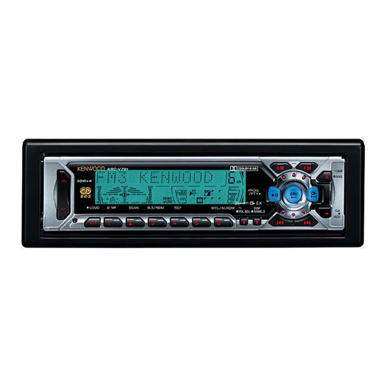
Panel assy
(A64-2576-02)
TE
L 13942296513
Knob(VOL)
(K25-1404-03)
DC cord
(E30-4942-05)
Plastic cabinet assy
(A02-1497-13)
www
.
Front glass
(B10-4155-01)
KRC-V791
50Wx4
LOUD
B NR
SCAN
B.S/RDM
Knob(1-6)
(K25-1405-02)
Remote controller assy
(A70-0886-15)
MASK-key
Lever
(D10-4562-04)x2
x
ao
u163
y
i
2 9
8
Knob(PROG)
Knob(FM,AM)
(K25-1407-03)
(K25-1406-03)
DOLBY B NR
PROG
/ P T Y
EX
REP
MTL/M.RDM
TI
DISP
VOL ADJ
NAME.S
Q Q
3
6 7
1 3
1 5
Knob(UP,DOWN)
(K25-1408-03)
Antenna adaptor
(T90-0523-05)
Remote controller assy
orsion coil spring
T
(A70-2025-05)
(G01-2924-04)
co
.
9 4
2 8
©
2001-11 PRINTED IN JAPAN
B51-7860-00 (S) 1922
Knob(SRC)
(K24-3835-04)
DAB
ANG
OFF
AUD
CLK
MENU
0 5
8
2 9
9 4
2 8
Front glass
(B10-4222-03)
Screw set
(N99-1704-05)
Mounting hardware assy
(J21-9716-03)
m
9 9
9 9
Advertisement

Related Manuals for Kenwood KRC-V791


Summary of Contents for Kenwood KRC-V791
- Page 1 CASSETTE RECEIVER KRC-V791 3 7 63 1515 0 SERVICE MANUAL © 2001-11 PRINTED IN JAPAN B51-7860-00 (S) 1922 The CASSETTE MECHANISM OPERATION DESCRIPTION is the same model D40-1122-05. Please refer to the service manual for model D40-1122-05(B51-7542-00). Knob(SRC) Panel assy...
- Page 2 3 7 6 3 1 5 1 5 0 ANT. TUNER A 8V SW5V FM+B FM : 245mV AM : 170mV AM+B B.U.5V Q1-4 IC11 MUTE 1.8V PRE OUT AUDIO BUFFER DRIVER SW5V DECODER E TYPE E-VOL TAPE 1800mV 388mV N.C.
- Page 3 KRC-V791 COMPONENT DESCRIPTION 3 7 63 1515 0 SWITCH UNIT(X16-1542-75) Component Purpose • Function Operation • Conditions • Compatibility LCD DRIVER with Key Matrix Remote Control IC D/A converter for controlling Variable Illumination Key Detection SW and Key Scan Start Lights key illumination in Red when the base of Q3 is "H".
- Page 4 KRC-V791 MICROCOMPUTER'S TERMINAL DESCRIPTION 3 7 63 1515 0 UPD703033GC138 (IC1: X14-) SYSTEM MICROCOMPUTER Name Purpose Operation Description AM+B AM power supply terminal. During AM operation: H. FM+B FM power supply terminal. During FM operation: H. Last FM with RDS model: H Constant switching when noise is detected.
- Page 5 KRC-V791 MICROCOMPUTER'S TERMINAL DESCRIPTION 3 7 63 1515 0 Name Purpose Operation Description Outputs Low. No connection. Outputs Low. No connection. ILL-ON FL +B output terminal. ON: H, OFF: L PAN-5V Panel 5 V control terminal. Panel detected: H Panel not detected: L Outputs Low.
- Page 6 KRC-V791 TEST MODE 3 7 63 1515 0 M&T-SRT Model Test Mode 1. How to enter the test mode 7. Audio-related specifications • While holding the FM and Preset 6 keys, reset the unit. • A short press of the Q key initiates the audio adjustment mode.
-
Page 7: Test Mode
KRC-V791 TEST MODE 3 7 63 1515 0 10. Special display when the display is All ON Security-related information Pressing the Preset keys while the power is All OFF • Forced Power ON mode (All models) displays the following information. - Page 8 KRC-V791 TEST MODE 3 7 63 1515 0 • Method of writing the Mask key while the EEPROM is in the initial status 1. Enter the test mode. (See 1 How to enter the test mode) 2. Press the CLK key to enter the Mask key registration mode.
- Page 9 KRC-V791 CIRCUIT DESCRIPTION 3 7 63 1515 0 New Variable Illumination Circuit • Theory In the following circuit, uses D/A converter which could adjust voltages with 256 grades within 0-5V, and control the current flowing to R2, R4 and R6 by changing its output power, so as to adjust the brightness of different colors (red, green, blue).
- Page 10 KRC-V791 ADJUSTMENT 3 7 63 1515 0 Set the controls and switches as follows. BALANCE :center position BASS :center position LOUD :OFF DOLBY NR :OFF FADER :center position TREBLE :center position TUNER OUTPUT ALIGNMENT ITEM INPUT SETTINGS (RECEIVER) ALIGN FOR FIG.
- Page 11 PC BOARD (Component Side View) 3 7 6 3 1 5 1 5 0 SWITCH UNIT SYNTHESIZER UNIT X14-6442-74 (J74-1140-12/J74-1397-02) X16-1542-75 (J74-1306-12) SWITCH UNIT SYNTHESIZER UNIT (X16-1542-75) (X14-6442-74) R136 PMUTE R134 R131 STBY C112 C131 C132 C154 R107 R100 C111 C135 C169 R162...
- Page 12 PC BOARD (Foil Side View) 3 7 6 3 1 5 1 5 0 SYNTHESIZER UNIT SWITCH UNIT X16-1542-75 (J74-1306-12) SWITCH UNIT SYNTHESIZER UNIT X14-6442-74 (J74-1140-12/J74-1397-02) (X16-1542-75) (X14-6442-74) ILL+B ILLUM G L-DATAS CLK L- L-CE L-DATAL C173 DIMMER DGND RESET R167 R315 R168...
- Page 13 PC BOARD 3 7 63 1515 0 Component Side View DOLBY UNIT X87-3022-72 (J74-1148-12) DOLBY L DOLBY R DOLBY L 13942296513 Foil Side View DOLBY UNIT X87-3022-72(J74-1148-12) u163 Refer to the schematic diagram for the values of resistors and capacitors.
- Page 14 GRN/BLK GRY/BLK VIOL/BLK VIOL BLU/WHT PNK/BLK EXT. CONT. ANT. CON BLU/WHT TEL MUTE ORG/WHT DC CORD (E30-4942) : KRC-791Y (E30-4956) : KRC-V791/791 L 13942296513 (X87-3022-7X) (X87-3022-7X) (X87-3022-7X) IC1 : CXA2560Q MODEL UNIT NAME EQ AMP Q1 : DTC124EK or 0.01...
- Page 15 PRE OUT FRONT REAR 3 7 6 3 1 5 1 5 0 DC IN (X14-6442-7X) F1 10A J3 TOP VIEW 1.45V CH CN 14.4V 7.5V 0V-4.1V 7.5V 1.25V REQ H D GND R24 22K R23 22K R38 22K R37 22K 3300u16 CH CON POWER IC...
- Page 16 ILL +B ILL +B TC74HC02AF C191 R194 C190 0.01 10u16 TDA7479D R193 100K (X14-6442-7X) SIGNAL LINE UNIT R323, MODEL NAME R324 R367 B LINE KRC-791 (E) 2-72 w w w KRC-791Y (E2) 2-73 KRC-V791 (E2) 2-74 u 1 6 3 KRC-V791...
- Page 17 C1 680P R1 43K : LC75808W 5.0V : RS-171 M62333FP Q1,6 : DTA114EUA or KRA302 Q3-5,62-64 : 2SC4081 Q50-55 UMX2N D5-18,20-22 : B30-1605-05 D23,24 B30-1564-05 MA3082-L D50-53 B30-1599-05 w w w GND LINE B LINE u 1 6 3 KRC-V791...
- Page 18 KRC-V791 KRC-V791 EXPLODED VIEW (MECHANISM) 3 7 6 3 1 5 1 5 0 EXPLODED VIEW (UNIT) FPC1 (X87-) 1 3 9 4 2 2 9 6 5 1 3 (X14) (X16) (X16) FPC2 (X14-) (X16-) w w w u 1 6 3 (X16) Parts with exploded numbers larger than 700 are not suppied.
- Page 19 KRC-V791 3 7 63 1515 0 PARTS LIST ∗ New Parts The language of an instruction manual. E : ENG F : FRE P : POR H : HUN O : POL Parts without Parts No. are not supplied. G : GER...
- Page 20 KRC-V791 3 7 63 1515 0 PARTS LIST ∗ New Parts Parts without Parts No. are not supplied. Les articles non mentionnes dans le Parts No. ne sont pas fournis. SYNTHESIZER UNIT (X14-6442-74) Teile ohane Parts No. werden nicht geliefert.
- Page 21 KRC-V791 3 7 63 1515 0 PARTS LIST ∗ New Parts Parts without Parts No. are not supplied. Les articles non mentionnes dans le Parts No. ne sont pas fournis. SYNTHESIZER UNIT (X14-6442-74) Teile ohane Parts No. werden nicht geliefert.
- Page 22 KRC-V791 3 7 63 1515 0 PARTS LIST SYNTHESIZER UNIT (X14-6442-74) ∗ New Parts SUB CIRCUIT UNIT (X16-1182-71) Parts without Parts No. are not supplied. SWITCH UNIT (X16-1542-75) Les articles non mentionnes dans le Parts No. ne sont pas fournis.
- Page 23 KRC-V791 3 7 63 1515 0 PARTS LIST ∗ New Parts Parts without Parts No. are not supplied. DOLBY UNIT (X87-3022-72) Les articles non mentionnes dans le Parts No. ne sont pas fournis. CASSETTE MECHANISM ASSY (D40-1146-05) Teile ohane Parts No. werden nicht geliefert.
-
Page 24: Parts List
KRC-V791 3 7 63 1515 0 PARTS LIST ∗ New Parts Parts without Parts No. are not supplied. Les articles non mentionnes dans le Parts No. ne sont pas fournis. CASSETTE MECHANISM ASSY (D40-1146-05) Teile ohane Parts No. werden nicht geliefert. - Page 25 KRC-V791 3 7 63 1515 0 CAPACITORS CC 45 TH 1H Capacitor value Color* CC45 010 = 1pF 0 = 22pF 100 = 10pF 1 = Type ... ceramic, electrolytic, etc. 4 = Voltage rating Multiplier 2 = Shape ... round, square, ect.
-
Page 26: Specifications
(H) ....... 53 mm (D) ....... 155 mm Weight ........... 1.4 kg KENWOOD follows a policy of continuous advancements in development. For this reason specifications may be changed without notice. US and foreign patents licensed from Dolby Laboratories Licensing Corporation. u163...