Sony DSR-PD170 Service Manual
Digital camcorder
Hide thumbs
Also See for DSR-PD170:
- Operating instructions manual (176 pages) ,
- Quick start manual (37 pages) ,
- Service manual (19 pages)
Table of Contents
Advertisement
Quick Links
SERVICE MANUAL
Ver 1.3 2005. 11
Revision History
Revision History
How to use
How to use
Acrobat Reader
Acrobat Reader
Link
Link
SPECIFICATIONS
SPECIFICATIONS
SERVICE NOTE
SERVICE NOTE
DISASSEMBLY
DISASSEMBLY
• INSTRUCTION MANUAL is shown at the end of this document.
• Reference No. search on printed wiring boards is available.
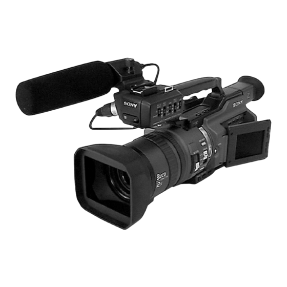
DSR-PD170/PD170P
Photo : DSR-PD170
BLOCK DIAGRAMS
BLOCK DIAGRAMS
FRAME SCHEMATIC DIAGRAMS
FRAME SCHEMATIC DIAGRAMS
SCHEMATIC DIAGRAMS
SCHEMATIC DIAGRAMS
/PD190P
RMT-811
US Model
Canadian Model
AEP Model
UK Model
E Model
DSR-PD170P
Chinese Model
DSR-PD190P
C MECHANISM
PRINTED WIRING BOARDS
PRINTED WIRING BOARDS
REPAIR PARTS LIST
REPAIR PARTS LIST
ADJUSTMENTS
ADJUSTMENTS
DIGITAL CAMCORDER
DSR-PD170
Advertisement
Chapters
Table of Contents

Related Manuals for Sony DSR-PD170


Summary of Contents for Sony DSR-PD170
- Page 1 Revision History Revision History E Model DSR-PD170P How to use How to use Chinese Model Acrobat Reader Acrobat Reader DSR-PD190P Photo : DSR-PD170 C MECHANISM Link Link SPECIFICATIONS BLOCK DIAGRAMS PRINTED WIRING BOARDS SPECIFICATIONS BLOCK DIAGRAMS PRINTED WIRING BOARDS SERVICE NOTE...
- Page 2 CRITIQUES POUR LA SÉCURITÉ DE FONCTIONNEMENT. NE COMPONENTS WITH SONY PARTS WHOSE PART NUMBERS REMPLACER CES COMPOSANTS QUE PAR DES PIÈSES SONY APPEAR AS SHOWN IN THIS MANUAL OR IN SUPPLEMENTS DONT LES NUMÉROS SONT DONNÉS DANS CE MANUEL OU PUBLISHED BY SONY.
- Page 3 DSR-PD170/PD170P/PD190P SAFETY CHECK-OUT After correcting the original service problem, perform the following safety checks before releasing the set to the customer. Unleaded solder Check the area of your repair for unsoldered or poorly-soldered Boards requiring use of unleaded solder are printed with the lead- connections.
-
Page 4: Table Of Contents
DSR-PD170/PD170P/PD190P TABLE OF CONTENTS SERVICE NOTE • LA-028 (1/3) (ZOOM/FOCUS DRIVE) SCHEMATIC DIAGRAM ···························· 4-19 1-1. NOTE FOR REPAIR ······················································· 1-1 • SE-147 (VAP SENSOR) 1-2. POWER SUPPLY DURING REPAIRS ·························· 1-2 SCHEMATIC DIAGRAM ···························· 4-19 1-3. TO TAKE OUT A CASSETTE WHEN NOT EJECT •... -
Page 5: Repair Parts List
DSR-PD170/PD170P/PD190P • VC-358D (14/18) (DRUM/CAPSTAN MOTOR DRIVE) • XS-004 (MIC SELECT) SCHEMATIC DIAGRAM ···························· 4-71 PRINTED WIRING BOARD ····················· 4-127 • VC-358D (15/18) (HI CONTROL) • XD-003 (DC/DC CONVERTER, REMOTE SCHEMATIC DIAGRAM ···························· 4-73 COMMANDER RECEIVER) • VC-358D (16/18) (AU LINE A/D, D/A) PRINTED WIRING BOARD ·····················... - Page 6 DSR-PD170/PD170P/PD190P Picture Frame Setting ···················································· 6-21 2-2-14. L Motor Assembly, Motor Shield, FP-248 Flexible Pre White Balance Data Input ······································· 6-22 Board, TG1 Spring Hook, Spring Hook Fulcrum Base, Auto White Balance Standard Data Input ····················· 6-22 Spring Hook Driving Arm, Worm Shaft, Deceleration MAX GAIN Adjustment ···············································...
- Page 7 DSR-PD170/PD170P/PD190P Overall Distortion Check ··············································· 6-73 Overall Noise Level Check ············································ 6-73 Overall Separation Check ·············································· 6-73 6-4. SERVICE MODE ·························································· 6-74 4-1. ADJUSTMENT REMOTE COMMANDER ················ 6-74 Using the adjustment remote commander ····················· 6-74 Precautions upon using ·················································· 6-74 the adjustment remote commander ································...
-
Page 8: Service Note
DSR-PD170/PD170P/PD190P SECTION 1 SERVICE NOTE 1-1. NOTE FOR REPAIR Make sure that the flat cable and flexible board are not cracked of When remove a connector, don’t pull at wire of connector. bent at the terminal. It is possible that a wire is snapped. -
Page 9: Power Supply During Repairs
DSR-PD170/PD170P/PD190P 1-2. POWER SUPPLY DURING REPAIRS In this unit, about 10 seconds after power is supplied to the battery terminal using the regulated power supply (8.4V), the power is shut off so that the unit cannot operate. These following two methods are available to prevent this. Take note of which to use during repairs. -
Page 10: Self-Diagnosis Function
DSR-PD170/PD170P/PD190P 1-4. SELF-DIAGNOSIS FUNCTION 1-4-1. Self-diagnosis Function 1-4-2. Self-diagnosis Display When problems occur while the unit is operating, the self-diagnosis When problems occur while the unit is operating, the counter of the function starts working, and displays on the viewfinder, LCD screen viewfinder, LCD screen or LCD window consists of an alphabet or LCD window what to do. -
Page 11: Self-Diagnosis Code Table
DSR-PDD170/PD170P/PD190P 1-4-3. Self-diagnosis Code Table Self-diagnosis Code Block Detailed Symptom/State Correction Function Code Non-standard battery is used. Use the info LITHIUM battery. Condensation. Remove the cassette, and insert it again after one hour. Video head is dirty. Clean with the optional cleaning cassette. LOAD direction. -
Page 12: Disassembly
DSR-PD170/PD170P/PD190P SECTION 2 DISASSEMBLY The following flow chart shows the disassembly procedure. 2-1. LCD section HL-013, PD-217 boards service position (HL-013, PD-217 boards, Inverter transformer unit) LB-100D board service position 2-2. EVF section (LB-100D board) 2-4. FK-088, MA-430D, RM-091, XD-003, XS-004, 2-3. -
Page 13: Lcd Section (Hl-013, Pd-217 Boards, Inverter Transformer Unit)
DSR-PD170/PD170P/PD190P NOTE: Follow the disassembly procedure in the numerical order given. 2-1. LCD SECTION (HL-013, PD-217 BOARDS, INVERTER TRANSFORMER UNIT) REMOVING THE PD-217 BOARD, INVERTER TRANSFORMER UNIT 2 Two screws (M2 × 3), 3 P cabinet (C) (D) assembly 4 Harness... -
Page 14: Evf Section (Lb-100D Board)
DSR-PD170/PD170P/PD190P 2-2. EVF SECTION (LB-100D BOARD) 2 EVF rear cabinet assembly 4 EVF front cabinet (upper) 1 Push the lock knob in the direction of the arrow A and remove the EVF rear cabinet assembly in the direction of the arrow B . -
Page 15: Upper) Handle Block Assembly
DSR-PD170/PD170P/PD190P 2-3. (UPPER) HANDLE BLOCK ASSEMBLY 9 (Upper) handle block assembly 6 Tilt down 4 Tilt up the finder. the finder. 2 Two screws (M2 × 5), lock ace 3 Screw (M2 × 5), lock ace 1 Two screws (M2 × 5),... -
Page 16: Boards
DSR-PD170/PD170P/PD190P 2-4. FK-088, MA-430D, RM-091, XD-003, XS-004, XM-005, XZ-003 BOARDS 1 RM-091 board (21P) 4 Handle cover 1 Three screws 3 MA-430D (D) assembly (M2 × 5), board (23P) lock ace 5 RM-091 board (7P) 7 Tapping screw 9 Cabinet (upper) (B2 ×... - Page 17 DSR-PD170/PD170P/PD190P [FK-088, MA-430D, RM-091, XD-003, XS-004, XM-005 BOARDS SERVICE POSITION] MA-430D board FP-897 flexible XZ-003 board FP-217 flexible RM-091 board board (21P) board (16P) XM-005 board FP-218 flexible board (13P) CPC-13 jig XS-004 board XD-003 board (J-6082-443-A) FK-088 board Adjustment remote...
-
Page 18: Cabinet (L) Block Assembly, Mechanism Deck, Vc-358D, Dd-216D, Jk-267 Boards
DSR-PD170/PD170P/PD190P 2-5. CABINET (L) BLOCK ASSEMBLY, MECHANISM DECK, VC-358D, DD-216D, JK-267 BOARDS (FOR FORCE EJECT OF CASSETTE AND VTR SECTION CHECK) 3 Screw (M2 × 5), spring bolt 6 Cabinet (L) block assembly 1 Screw (FOR FORCE EJECT OF CASSETTE) (M2 ×... - Page 19 DSR-PD170/PD170P/PD190P [MECHANISM DECK SERVICE POSITION-1] Note: Use the parts only which can be removed easily from outside of the mechanism deck. Adjustment remote commander (RM-95) CPC-13 jig Mechanism deck (J-6082-443-A) AC POWER AC IN ADAPTOR Cabinet (L) block assembly [SERVICE POSITION TO CHECK THE VTR SECTION] Connection to Check the VTR Section To check the VTR Section, set the VTR to the "forced VTR power ON"...
-
Page 20: Cabinet (R) Block Assembly
DSR-PD170/PD170P/PD190P 2-6. CABINET (R) BLOCK ASSEMBLY 5 Screw (M2 × 5), spring bolt 7 Cabinet (R) block assembly 6 Two screws (M2 × 5), lock ace 1 Screw (M2 × 5), spring bolt 3 CF ornamental plate 4 Two screws (M2 ×... -
Page 21: Battery Panel Block Assembly (Mk-016, Kp-013, Ms-209 Boards)
DSR-PD170/PD170P/PD190P 2-8. BATTERY PANEL BLOCK ASSEMBLY (MK-016, KP-013, MS-209 BOARDS) 9 CPC cover 8 Screw (M2 × 5), q; Battery panel lock ace block assembly 7 Two screws (M2 × 5), lock ace 6 Two screws (M2 × 5), lock ace 4 Screw (M2 ×... - Page 22 DSR-PD170/PD170P/PD190P 2-10.LA-028, DD-216D, VC-358D, JK-267 BOARDS, MECHANISM DECK 1 Screw (M2 × 3), lock ace 2 Flexible retainer 8 Screw (M2 × 3), lock ace 9 LA joint 3 FP-188 flexible board (6P) 7 LA-028 board 6 Three screws (M2 × 3),...
-
Page 23: Mechanism Deck
DSR-PD170/PD170P/PD190P 2-11.LENS BLOCK ASSEMBLY, CENTER FRAME (D) ASSEMBLY qs FP-188 flexible board (6P) qd Center frame (D) assembly q; Two screws (M2 × 4), 6 Screw lock ace (M2 × 3), qa Two screws (M2 × 3), lock ace lock ace... -
Page 24: Control Switch Block (Ps-4980)
DSR-PD170/PD170P/PD190P 2-12.CD-512, SE-147 BOARDS, ZOOM LENS ASSEMBLY 1 Three tapping 4 Three tapping screws screws (M1.7 × 7) (B2 × 5) 5 SE-147 board 2 (CCD) flexible block assembly 3 Flexible board (6P) (from zoom lens assembly) REMOVING THE CD-512 BOARD 9 Zoom lens 8 Remove the soldering. - Page 25 DSR-PD170/PD170P/PD190P [CONNECTION DIAGRAM FOR SERVICE POSITION (Mainly for voltage measurement and check)] CK-140, VC-358D, JK-267, CD-512, DD-216D, LA-028, KP-013, MK-016, MS-209 BOARDS, MECHANISM DECK-2 Battery panel assembly AC POWER AC IN ADAPTOR CPC-13 jig DC-IN (J-6082-443-A) connector (3P) (1-794-637-21) Battery terminal board (4P)
- Page 26 DSR-PD170/PD170P/PD190P 2-15.CONTROL SWITCH BLOCK (ED-4980), HINGE ASSEMBLY Start the removal work after the LCD section has been removed referring section 2-1. 2 Control switch block (ED-4980) 1 Bright button 3 Blind door (D) assembly 2 Screw (M1.7 × 2.5), 2 Hinge lid...
- Page 27 DSR-PD170/PD170P/PD190P 2-16.CIRCUIT BOARDS LOCATION The circuit boards contained in the zoom lens are not shown. XD-003 DC/DC CONVERTER, REMOTE COMMANDER RECEIVER MA-430D LB-100D (AUDIO AMP) CK-140 (BACK LIGHT) XM-005 (KEY IN) (MIC AMP) PD-217 (RGB DRIVE, TG) INVERTER TRANSFORMER UNIT...
-
Page 28: Control Switch Block (Ed-4980)
DSR-PD170/PD170P/PD190P 2-17.FLEXIBLE BOARDS LOCATION The flexible boards contained in the mechanism deck and that in the zoom lens are not shown. FP-193 FP-895 FP-202 FP-897 FP-194 FP-190 FP-196 FP-189 FP-188 FP-195 FP-191 CONTROL SWITCH BLOCK (ED-4980) CONTROL SWITCH BLOCK FP-186... -
Page 29: Overall Block Diagram (3/4)
DSR-PD170/PD170P/PD190P 3. BLOCK DIAGRAMS Link Link OVERALL BLOCK DIAGRAM (1/4) POWER BLOCK DIAGRAM (1/3) OVERALL BLOCK DIAGRAM (1/4) POWER BLOCK DIAGRAM (1/3) OVERALL BLOCK DIAGRAM (2/4) POWER BLOCK DIAGRAM (2/3) OVERALL BLOCK DIAGRAM (2/4) POWER BLOCK DIAGRAM (2/3) OVERALL BLOCK DIAGRAM (3/4) - Page 30 DSR-PD170/PD170P/PD190P SECTION 3 3. BLOCK DIAGRAMS 3. BLOCK DIAGRAMS BLOCK DIAGRAMS 3-1. OVERALL BLOCK DIAGRAM (1/4) ( ) : Number in parenthesis ( ) indicates the division number of schematic diagram where the component is located. CD-512 BOARD VC-358D BOARD(1/4)
- Page 31 DSR-PD170/PD170P/PD190P 3. BLOCK DIAGRAMS 3. BLOCK DIAGRAMS ( ) : Number in parenthesis ( ) indicates the division number of schematic diagram where the component is located. 3-2. OVERALL BLOCK DIAGRAM (2/4) CN300 VC-358D BOARD(2/4) DV Interface (6/18) (3/18) X301 24.576MHz...
- Page 32 DSR-PD170/PD170P/PD190P 3. BLOCK DIAGRAMS 3. BLOCK DIAGRAMS 3-3. OVERALL BLOCK DIAGRAM (3/4) ( ) : Number in parenthesis ( ) indicates the division number of schematic diagram where the component is located. CN007 C MECHA DECK FOR ADJUSTMENTS (8/18) VC-358D BOARD(3/4)
- Page 33 DSR-PD170/PD170P/PD190P 3. BLOCK DIAGRAMS 3. BLOCK DIAGRAMS ( ) : Number in parenthesis ( ) indicates the division number of schematic diagram where the component is located. 3-4. OVERALL BLOCK DIAGRAM (4/4) CONTROL FP-196 HL-013 BOARD CK-140 PD-217 VC-358D BOARD(4/4)
- Page 34 DSR-PD170/PD170P/PD190P 3. BLOCK DIAGRAMS 3. BLOCK DIAGRAMS 3-5. POWER BLOCK DIAGRAM (1/3) ( ) : Number in parenthesis ( ) indicates the division number of schematic diagram where the component is located. CHARGE INH DD-216D BOARD SHOE ON SHOE UNREG...
- Page 35 DSR-PD170/PD170P/PD190P 3. BLOCK DIAGRAMS 3. BLOCK DIAGRAMS ( ) : Number in parenthesis ( ) indicates the division number of schematic diagram where the component is located. 3-6. POWER BLOCK DIAGRAM (2/3) VC-358D BOARD IC1104 (15/18) JK-267 BOARD CN021 HI CONTROL...
- Page 36 DSR-PD170/PD170P/PD190P 3. BLOCK DIAGRAMS 3. BLOCK DIAGRAMS 3-7. POWER BLOCK DIAGRAM (3/3) ( ) : Number in parenthesis ( ) indicates the division number of schematic diagram where the component is located. RM-091 BOARD S803,804,801 CN801 PD-217 BOARD XD-003 BOARD ZOOM SW D 2.8V...
-
Page 37: Printed Wiring Boards And Schematic Diagrams
DSR-PD170/PD170P/PD190P 4-2. SCHEMATIC DIAGRAMS 4-2. SCHEMATIC DIAGRAMS 4-3. PRINTED WIRING BOARDS 4-3. PRINTED WIRING BOARDS SECTION 4 PRINTED WIRING BOARDS AND SCHEMATIC DIAGRAMS 4-1. FRAME SCHEMATIC DIAGRAM (1/3) CN100 IMAGER SUBB CD-512 BOARD VDDB B_CCD_OUT IMAGER LENS UNIT V2BB VDD2B... -
Page 38: Frame Schematic Diagram (1/3)
DSR-PD170/PD170P/PD190P 4-2. SCHEMATIC DIAGRAMS 4-2. SCHEMATIC DIAGRAMS 4-3. PRINTED WIRING BOARDS 4-3. PRINTED WIRING BOARDS FRAME SCHEMATIC DIAGRAM (2/3) CN025 LB-100D BOARD SUBB LCD903 UNIT VDDB CN300 B_CCD_OUT JK-267 BOARD NTPA Interface V2BB VDD2B V2AB NTPB R_CCD_OUT VDD2R CONTINUED ON... -
Page 39: Frame Schematic Diagram (2/3)
DSR-PD170/PD170P/PD190P 4-2. SCHEMATIC DIAGRAMS 4-2. SCHEMATIC DIAGRAMS 4-3. PRINTED WIRING BOARDS 4-3. PRINTED WIRING BOARDS FRAME SCHEMATIC DIAGRAM (3/3) CONTROL SWITCH BLOCK(ED-4980) FP-197 FP-194 ND901 BACK-LIGHT FLEXIBLE FLEXIBLE CONTROL DIAL COLOR LCD901 UNIT INVERTER UNIT CN1703 CN253 COM4 COM3 SP901... -
Page 40: Schematic Diagrams
DSR-PD170/PD170P/PD190P 4-2. SCHEMATIC DIAGRAMS (1/2) Link Link TO (2/2) TO (2/2) CD-512 BOARD FK-088 BOARD CD-512 BOARD FK-088 BOARD (CONTROL SWITCH) (CCD IMAGER) (CCD IMAGER) (CONTROL SWITCH) XZ-003 BOARD JK-267 BOARD XZ-003 BOARD (LITHIUM BATTERY, SW) JK-267 BOARD (JACK BOARD) -
Page 41: Schematic Diagram
DSR-PD170/PD170P/PD190P 4-2. SCHEMATIC DIAGRAMS (2/2) Link Link TO (1/2) TO (1/2) VC-358D BOARD (14/18) VC-358D BOARD (14/18) VC-358D BOARD (5/18) VC-358D BOARD (5/18) (MS DRIVE) (MS DRIVE) (DRUM/CAPSTAN MOTOR DRIVE) (DRUM/CAPSTAN MOTOR DRIVE) VC-358D BOARD (6/18) VC-358D BOARD (15/18) VC-358D BOARD (6/18) -
Page 42: Schematic Diagram
DSR-PD170/PD170P/PD190P 4-2. SCHEMATIC DIAGRAMS 4-2. SCHEMATIC DIAGRAMS THIS NOTE IS COMMON FOR SCHEMATIC DIAGRAMS (In addition to this, the necessary note is printed in each block) (For schematic diagrams) 1. Connection • All capacitors are in µF unless otherwise noted. pF : µ... -
Page 43: Schematic Diagram
MOS IC. In addition, ensure that the receiver is not covered with dusts L105 100uH nor exposed to strog light. C108 R111 6.3V R110 C110 NTSC MODEL;DSR-PD170 R105 4.7u PAL MODEL ;DSR-PD170P/PD190P 5600 IC105 BUFFER IC100 IC105 AD8014ART-REEL7... - Page 44 DSR-PD170/PD170P/PD190P 4-2. SCHEMATIC DIAGRAMS 4-2. SCHEMATIC DIAGRAMS JK-267 PRINTED WIRING BOARD JK-267 PRINTED WIRING BOARD For Schematic Diagram • Refer to page 4-93 for printed wiring board. SIGNAL PATH JK-267 BOARD JACK BOARD VIDEO SIGNAL AUDIO XX MARK:NO MOUNT CHROMA...
- Page 45 DSR-PD170/PD170P/PD190P 4-2. SCHEMATIC DIAGRAMS 4-2. SCHEMATIC DIAGRAMS CK-140 PRINTED WIRING BOARD CK-140 PRINTED WIRING BOARD For Schematic Diagram • Refer to page 4-95 for printed wiring board. CK-140 BOARD CONTROL SWITCH BLOCK(ED-4980) KEY IN S001 XX MARK:NO MOUNT IRIS CN255...
- Page 46 DSR-PD170/PD170P/PD190P 4-2. SCHEMATIC DIAGRAMS PD-217 PRINTED WIRING BOARD 4-2. SCHEMATIC DIAGRAMS PD-217 PRINTED WIRING BOARD For Schematic Diagram • Refer to page 4-97 for printed wiring board of PD-217 board. • Refer to page 4-101 for printed wiring board of SE-147 board.
- Page 47 DSR-PD170/PD170P/PD190P 4-2. SCHEMATIC DIAGRAMS LA-028 BOARD SE-147 BOARD 4-2. SCHEMATIC DIAGRAMS LA-028 BOARD SE-147 BOARD For Schematic Diagram • Refer to page 4-99 for printed wiring board. LA-028 BOARD(1/3) ZOOM/FOCUS DRIVE(LA BLOCK) XX MARK:NO MOUNT NO MARK:REC/PB MODE HALL_AD (3/3)
- Page 48 DSR-PD170/PD170P/PD190P 4-2. SCHEMATIC DIAGRAMS 4-2. SCHEMATIC DIAGRAMS LA-028 PRINTED WIRING BOARD LA-028 PRINTED WIRING BOARD For Schematic Diagram • Refer to page 4-99 for printed wiring board. LA-028 BOARD(2/3) Q071 Q070 R5.1/P0 2SB1462J-QR(K8).SO 2SB1462J-QR(K8).SO VAP DRIVE(LD BLOCK) R085 IC072 IC072...
- Page 49 DSR-PD170/PD170P/PD190P 4-2. SCHEMATIC DIAGRAMS 4-2. SCHEMATIC DIAGRAMS LA-028 PRINTED WIRING BOARD LA-028 PRINTED WIRING BOARD For Schematic Diagram • Refer to page 4-99 for printed wiring board. LA-028 BOARD(3/3) D_3.1V (1/3) (2/3) KEY IN/CONNECTOR(CN BLOCK) NO MARK:REC/PB MODE R :REC MODE...
- Page 50 DSR-PD170/PD170P/PD190P 4-2. SCHEMATIC DIAGRAMS 4-2. SCHEMATIC DIAGRAMS MS-209 BOARD MS-209 BOARD KP-013 BOARD KP-013 BOARD MK-016 BOARD MK-016 BOARD For Schematic Diagram • Refer to page 4-103 for printed wiring board of MS-209 board. • Refer to page 4-105 for printed wiring board of KP-013 and MK-016 boards.
- Page 51 DSR-PD170/PD170P/PD190P 4-2. SCHEMATIC DIAGRAMS 4-2. SCHEMATIC DIAGRAMS FK-088 PRINTED WIRING BOARD FK-088 PRINTED WIRING BOARD For Schematic Diagram • Refer to page 4-107 for printed wiring board. CN502 ZM_SPD_SEL FK-088 BOARD XS/S_SW(HAND) CONTROL SWITCH H_ZOOM_AD R502 R505 R508 R511 R514...
- Page 52 DSR-PD170/PD170P/PD190P 4-2. SCHEMATIC DIAGRAMS 4-2. SCHEMATIC DIAGRAMS XZ-003 PRINTED WIRING BOARD XZ-003 PRINTED WIRING BOARD For Schematic Diagram • Refer to page 4-119 for printed wiring board. XZ-003 BOARD LITHIUM BATTERY,SW XX MARK:NO MOUNT (HANDLE ZOOM) S804 S803 R801 R804...
- Page 53 DSR-PD170/PD170P/PD190P 4-2. SCHEMATIC DIAGRAMS 4-2. SCHEMATIC DIAGRAMS LB-100D PRINTED WIRING BOARD LB-100D PRINTED WIRING BOARD For Schematic Diagram • Refer to page 4-111 for printed wiring board of LB-100 board. LB-100D BOARD BACK LIGHT XX MARK:NO MOUNT CN200 CN201 R205...
- Page 54 DSR-PD170/PD170P/PD190P 4-2. SCHEMATIC DIAGRAMS 4-2. SCHEMATIC DIAGRAMS HL-013 PRINTED WIRING BOARD HL-013 PRINTED WIRING BOARD For Schematic Diagram • Refer to page 4-113 for printed wiring board. HL-013 BOARD NO MARK:REC/PB MODE R :REC MODE LCD DRIVE P :PB MODE...
- Page 55 DSR-PD170/PD170P/PD190P 4-2. SCHEMATIC DIAGRAMS 4-2. SCHEMATIC DIAGRAMS MA-430D PRINTED WIRING BOARD MA-430D PRINTED WIRING BOARD For Schematic Diagram • Refer to page 4-115 for printed wiring board. MA-430D BOARD AUDIO AMP SIGNAL PATH XX MARK:NO MOUNT AUDIO SIGNAL CN1100 SIRCS_SIG1...
- Page 56 DSR-PD170/PD170P/PD190P 4-2. SCHEMATIC DIAGRAMS 4-2. SCHEMATIC DIAGRAMS DD-216D PRINTED WIRING BOARD DD-216D PRINTED WIRING BOARD For Schematic Diagram • Refer to page 4-117 for printed wiring board. DD-216D BOARD(1/2) DC/DC CONVERTER(DD-1 BLOCK) XX MARK:NO MOUNT CHARGE_INH (2/2) R300 BATT/XEXT_SW (2/2)
- Page 57 DSR-PD170/PD170P/PD190P 4-2. SCHEMATIC DIAGRAMS 4-2. SCHEMATIC DIAGRAMS DD-216D PRINTED WIRING BOARD DD-216D PRINTED WIRING BOARD For Schematic Diagram • Refer to page 4-117 for printed wiring board. DD-216D BOARD(2/2) DC REGURATOR(DD-2 BLOCK) SIGNAL PATH XX MARK:NO MOUNT REC/PB NO MARK:REC/PB MODE...
- Page 58 DSR-PD170/PD170P/PD190P 4-2. SCHEMATIC DIAGRAMS 4-2. SCHEMATIC DIAGRAMS 4-3. PRINTED WIRING BOARDS 4-3. PRINTED WIRING BOARDS CONTROL SWITCH BLOCK(CF-4980) RV800 CN011 (ZOOM) D_2.8V S811 ZOOM_VR_AD PHOTO XPHOTO_FREEZE XPHOTO_REC XEJECT_SW VC-358D BOARD(15/18) CN009 XS/S_SW PHOTO_STBY_SW XVTR_MODE_SW (PAGE 4-74) XCAM+STBY_SW XCAM+STBY_SW XVTR_MODE_SW PHOTO_STBY_SW...
- Page 59 DSR-PD170/PD170P/PD190P 4-2. SCHEMATIC DIAGRAMS 4-2. SCHEMATIC DIAGRAMS RM-091 PRINTED WIRING BOARD RM-091 PRINTED WIRING BOARD For Schematic Diagram • Refer to page 4-121 for printed wiring board. ZM_SPD_SEL RM-091 BOARD XS/S_SW(HAND) REAR REMOTE COMMANDER RECEIVER H_ZOOM_AD XX MARK:NO MOUNT SIRCS_SIG1 D_2.8V...
- Page 60 DSR-PD170/PD170P/PD190P 4-2. SCHEMATIC DIAGRAMS 4-2. SCHEMATIC DIAGRAMS VC-358D BOARD SIDE A VC-358D BOARD SIDE A VC-358D BOARD SIDE B VC-358D BOARD SIDE B For Schematic Diagram • Refer to page 4-123 for printed wiring board. VC-358D BOARD(1/18) S/H AGC,TG(CA(CH)BLOCK) C719...
- Page 61 DSR-PD170/PD170P/PD190P 4-2. SCHEMATIC DIAGRAMS 4-2. SCHEMATIC DIAGRAMS VC-358D BOARD SIDE A VC-358D BOARD SIDE A VC-358D BOARD SIDE B VC-358D BOARD SIDE B For Schematic Diagram • Refer to page 4-123 for printed wiring board. VC-358D BOARD(2/18) SIGNAL PATH CAMERA SIGNAL PROCESS(CA(U-C)BLOCK)
- Page 62 DSR-PD170/PD170P/PD190P 4-2. SCHEMATIC DIAGRAMS 4-2. SCHEMATIC DIAGRAMS VC-358D BOARD SIDE A VC-358D BOARD SIDE A VC-358D BOARD SIDE B VC-358D BOARD SIDE B For Schematic Diagram • Refer to page 4-123 for printed wiring board. VC-358D BOARD(3/18) :Voltage measurement of the CSP IC...
- Page 63 DSR-PD170/PD170P/PD190P 4-2. SCHEMATIC DIAGRAMS 4-2. SCHEMATIC DIAGRAMS VC-358D BOARD SIDE A VC-358D BOARD SIDE A VC-358D BOARD SIDE B VC-358D BOARD SIDE B For Schematic Diagram • Refer to page 4-123 for printed wiring board. VC-358D BOARD(4/18) RS-232C, I/F STILL CONTROL (MS-2 BLOCK) D_2.8V...
- Page 64 DSR-PD170/PD170P/PD190P 4-2. SCHEMATIC DIAGRAMS 4-2. SCHEMATIC DIAGRAMS VC-358D BOARD SIDE A VC-358D BOARD SIDE A VC-358D BOARD SIDE B VC-358D BOARD SIDE B For Schematic Diagram • Refer to page 4-123 for printed wiring board. IC1411 VC-358D BOARD(5/18) X1402 20MHz...
- Page 65 DSR-PD170/PD170P/PD190P 4-2. SCHEMATIC DIAGRAMS 4-2. SCHEMATIC DIAGRAMS VC-358D BOARD SIDE A VC-358D BOARD SIDE A VC-358D BOARD SIDE B VC-358D BOARD SIDE B For Schematic Diagram • Refer to page 4-123 for printed wiring board. VC-358D BOARD(6/18) :Voltage measurement of...
- Page 66 DSR-PD170/PD170P/PD190P 4-2. SCHEMATIC DIAGRAMS 4-2. SCHEMATIC DIAGRAMS VC-358D BOARD SIDE A VC-358D BOARD SIDE A VC-358D BOARD SIDE B VC-358D BOARD SIDE B For Schematic Diagram • Refer to page 4-123 for printed wiring board. VC-358D BOARD(7/18) SIGNAL PATH :Voltage measurement of...
- Page 67 DSR-PD170/PD170P/PD190P 4-2. SCHEMATIC DIAGRAMS 4-2. SCHEMATIC DIAGRAMS VC-358D BOARD SIDE A VC-358D BOARD SIDE A VC-358D BOARD SIDE B VC-358D BOARD SIDE B For Schematic Diagram • Refer to page 4-123 for printed wiring board. VC-358D BOARD(8/18) NO MARK:REC/PB MODE...
- Page 68 DSR-PD170/PD170P/PD190P 4-2. SCHEMATIC DIAGRAMS 4-2. SCHEMATIC DIAGRAMS VC-358D BOARD SIDE A VC-358D BOARD SIDE A VC-358D BOARD SIDE B VC-358D BOARD SIDE B For Schematic Diagram • Refer to page 4-123 for printed wiring board. (1/18) VC-358D BOARD(9/18) A_4.6V (10/18)
- Page 69 DSR-PD170/PD170P/PD190P 4-2. SCHEMATIC DIAGRAMS 4-2. SCHEMATIC DIAGRAMS VC-358D BOARD SIDE A VC-358D BOARD SIDE A VC-358D BOARD SIDE B VC-358D BOARD SIDE B For Schematic Diagram • Refer to page 4-123 for printed wiring board. VC-358D BOARD(10/18) LINE A/D(IN BLOCK)
- Page 70 DSR-PD170/PD170P/PD190P 4-2. SCHEMATIC DIAGRAMS 4-2. SCHEMATIC DIAGRAMS VC-358D BOARD SIDE A VC-358D BOARD SIDE A VC-358D BOARD SIDE B VC-358D BOARD SIDE B For Schematic Diagram • Refer to page 4-123 for printed wiring board. VC-358D BOARD(11/18) RGB DRIVE/TG(VF BLOCK)
- Page 71 DSR-PD170/PD170P/PD190P 4-2. SCHEMATIC DIAGRAMS 4-2. SCHEMATIC DIAGRAMS VC-358D BOARD SIDE A VC-358D BOARD SIDE A VC-358D BOARD SIDE B VC-358D BOARD SIDE B For Schematic Diagram • Refer to page 4-123 for printed wiring board. VC-358D BOARD(12/18) CAMERA CONTROL(CA(MC) BLOCK)
- Page 72 DSR-PD170/PD170P/PD190P 4-2. SCHEMATIC DIAGRAMS 4-2. SCHEMATIC DIAGRAMS VC-358D BOARD SIDE A VC-358D BOARD SIDE A VC-358D BOARD SIDE B VC-358D BOARD SIDE B For Schematic Diagram • Refer to page 4-123 for printed wiring board. VC-358D BOARD(13/18) :Voltage measurement of the CSP IC...
- Page 73 DSR-PD170/PD170P/PD190P 4-2. SCHEMATIC DIAGRAMS 4-2. SCHEMATIC DIAGRAMS VC-358D BOARD SIDE A VC-358D BOARD SIDE A VC-358D BOARD SIDE B VC-358D BOARD SIDE B For Schematic Diagram • Refer to page 4-123 for printed wiring board. VC-358D BOARD(14/18) NO MARK:REC/PB MODE...
- Page 74 DSR-PD170/PD170P/PD190P 4-2. SCHEMATIC DIAGRAMS 4-2. SCHEMATIC DIAGRAMS VC-358D BOARD SIDE A VC-358D BOARD SIDE A VC-358D BOARD SIDE B VC-358D BOARD SIDE B For Schematic Diagram • Refer to page 4-123 for printed wiring board. VC-358D BOARD(15/18) NO MARK:REC/PB MODE...
- Page 75 DSR-PD170/PD170P/PD190P 4-2. SCHEMATIC DIAGRAMS 4-2. SCHEMATIC DIAGRAMS VC-358D BOARD SIDE A VC-358D BOARD SIDE A VC-358D BOARD SIDE B VC-358D BOARD SIDE B For Schematic Diagram • Refer to page 4-123 for printed wiring board. VC-358D BOARD(16/18) AU LINE A/D,D/A (AU-1 BLOCK)
- Page 76 DSR-PD170/PD170P/PD190P 4-2. SCHEMATIC DIAGRAMS 4-2. SCHEMATIC DIAGRAMS VC-358D BOARD SIDE A VC-358D BOARD SIDE A VC-358D BOARD SIDE B VC-358D BOARD SIDE B For Schematic Diagram • Refer to page 4-123 for printed wiring board. VC-358D BOARD(17/18) LINE AMP(AU-2 BLOCK)
- Page 77 DSR-PD170/PD170P/PD190P 4-2. SCHEMATIC DIAGRAMS 4-2. SCHEMATIC DIAGRAMS VC-358D BOARD SIDE A VC-358D BOARD SIDE A VC-358D BOARD SIDE B VC-358D BOARD SIDE B For Schematic Diagram • Refer to page 4-123 for printed wiring board. VC-358D BOARD(18/18) CONNECTOR(CN BLOCK) XX MARK:NO MOUNT...
- Page 78 DSR-PD170/PD170P/PD190P 4-2. SCHEMATIC DIAGRAMS 4-2. SCHEMATIC DIAGRAMS XD-003 BOARD XD-003 BOARD XS-004 BOARD XS-004 BOARD For Schematic Diagram • Refer to page 4-129 for printed wiring board of XD-003 baord. • Refer to page 4-127 for printed wiring board of XS-004 baord.
- Page 79 DSR-PD170/PD170P/PD190P 4-2. SCHEMATIC DIAGRAMS 4-2. SCHEMATIC DIAGRAMS XM-005 PRINTED WIRING BOARD XM-005 PRINTED WIRING BOARD For Schematic Diagram • Refer to page 4-109 for printed wiring board. XM-005 BOARD MIC AMP CN201 XX MARK:NO MOUNT CH1_(+)_ATT CH1_(+)_COM CH1_(+)_THR NO MARK:REC/PB MODE...
-
Page 80: Printed Wiring Boards
DSR-PD170/PD170P/PD190P 4-3. PRINTED WIRING BOARDS Link Link CD-512 BOARD FK-088 BOARD CD-512 BOARD FK-088 BOARD XM-005 BOARD FP-594 FLEXIBLE BOARD XM-005 BOARD FP-594 FLEXIBLE BOARD JK-267 BOARD LB-100D BOARD JK-267 BOARD LB-100D BOARD CK-140 BOARD HL-013 BOARD CK-140 BOARD HL-013 BOARD... - Page 81 DSR-PD170/PD170P/PD190P 4-3. PRINTED WIRING BOARDS 4-3. PRINTED WIRING BOARDS THIS NOTE IS COMMON FOR WIRING BOARDS (In addition to this, the necessary note is printed in each block) (For printed wiring boards) • Chip parts. • : Uses unleaded solder.
- Page 82 DSR-PD170/PD170P/PD190P MOUNTED PARTS LOCATION 4-2. SCHEMATIC DIAGRAMS 4-2. SCHEMATIC DIAGRAMS 4-3. PRINTED WIRING BOARDS 4-3. PRINTED WIRING BOARDS MOUNTED PARTS LOCATION 4-3. PRINTED WIRING BOARDS • : Uses unleaded solder. • Refer to page 4-87 for common note for printed wiring board.
- Page 83 DSR-PD170/PD170P/PD190P 4-2. SCHEMATIC DIAGRAMS 4-2. SCHEMATIC DIAGRAMS 4-3. PRINTED WIRING BOARDS 4-3. PRINTED WIRING BOARDS • : Uses unleaded solder. • Refer to page 4-87 for common note for printed wiring board. FP-594 BOARD M903 LOADING MOTOR SENSOR S903 MODE SW...
- Page 84 DSR-PD170/PD170P/PD190P Ver 1.1 2004. 07 MOUNTED PARTS LOCATION 4-2. SCHEMATIC DIAGRAMS 4-2. SCHEMATIC DIAGRAMS 4-3. PRINTED WIRING BOARDS 4-3. PRINTED WIRING BOARDS MOUNTED PARTS LOCATION • : Uses unleaded solder. • Refer to page 4-87 for common note for printed wiring board.
- Page 85 DSR-PD170/PD170P/PD190P MOUNTED PARTS LOCATION 4-2. SCHEMATIC DIAGRAMS 4-2. SCHEMATIC DIAGRAMS 4-3. PRINTED WIRING BOARDS 4-3. PRINTED WIRING BOARDS MOUNTED PARTS LOCATION • : Uses unleaded solder. • Refer to page 4-87 for common note for printed wiring board. CK-140 BOARD(SIDE B)
- Page 86 DSR-PD170/PD170P/PD190P MOUNTED PARTS LOCATION 4-2. SCHEMATIC DIAGRAMS 4-2. SCHEMATIC DIAGRAMS 4-3. PRINTED WIRING BOARDS 4-3. PRINTED WIRING BOARDS MOUNTED PARTS LOCATION • : Uses unleaded solder. • Refer to page 4-87 for common note for printed wiring board. PD-217 BOARD(SIDE A)
- Page 87 DSR-PD170/PD170P/PD190P MOUNTED PARTS LOCATION 4-2. SCHEMATIC DIAGRAMS 4-2. SCHEMATIC DIAGRAMS 4-3. PRINTED WIRING BOARDS 4-3. PRINTED WIRING BOARDS MOUNTED PARTS LOCATION • : Uses unleaded solder. • Refer to page 4-87 for common note for printed wiring board. LA-028 BOARD(SIDE A)
- Page 88 DSR-PD170/PD170P/PD190P MOUNTED PARTS LOCATION 4-2. SCHEMATIC DIAGRAMS 4-2. SCHEMATIC DIAGRAMS 4-3. PRINTED WIRING BOARDS 4-3. PRINTED WIRING BOARDS MOUNTED PARTS LOCATION • : Uses unleaded solder. • Refer to page 4-87 for common note for printed wiring board. SE-147 BOARD(SIDE A)
- Page 89 DSR-PD170/PD170P/PD190P MOUNTED PARTS LOCATION 4-2. SCHEMATIC DIAGRAMS 4-2. SCHEMATIC DIAGRAMS 4-3. PRINTED WIRING BOARDS 4-3. PRINTED WIRING BOARDS MOUNTED PARTS LOCATION • : Uses unleaded solder. • Refer to page 4-87 for common note for printed wiring board. MS-209 BOARD(SIDE A)
- Page 90 DSR-PD170/PD170P/PD190P MOUNTED PARTS LOCATION 4-2. SCHEMATIC DIAGRAMS 4-2. SCHEMATIC DIAGRAMS 4-3. PRINTED WIRING BOARDS 4-3. PRINTED WIRING BOARDS MOUNTED PARTS LOCATION • : Uses unleaded solder. • Refer to page 4-87 for common note for printed wiring board. KP-013 BOARD(SIDE A)
- Page 91 DSR-PD170/PD170P/PD190P MOUNTED PARTS LOCATION 4-2. SCHEMATIC DIAGRAMS 4-2. SCHEMATIC DIAGRAMS 4-3. PRINTED WIRING BOARDS 4-3. PRINTED WIRING BOARDS MOUNTED PARTS LOCATION • : Uses unleaded solder. • Refer to page 4-87 for common note for printed wiring board. FK-088 BOARD(SIDE A)
- Page 92 DSR-PD170/PD170P/PD190P MOUNTED PARTS LOCATION 4-2. SCHEMATIC DIAGRAMS 4-2. SCHEMATIC DIAGRAMS 4-3. PRINTED WIRING BOARDS 4-3. PRINTED WIRING BOARDS MOUNTED PARTS LOCATION • : Uses unleaded solder. • Refer to page 4-87 for common note for printed wiring board. XM-005 BOARD(SIDE A)
- Page 93 DSR-PD170/PD170P/PD190P MOUNTED PARTS LOCATION 4-2. SCHEMATIC DIAGRAMS 4-2. SCHEMATIC DIAGRAMS 4-3. PRINTED WIRING BOARDS 4-3. PRINTED WIRING BOARDS MOUNTED PARTS LOCATION • : Uses unleaded solder. • Refer to page 4-87 for common note for printed wiring board. LB-100D BOARD...
- Page 94 DSR-PD170/PD170P/PD190P MOUNTED PARTS LOCATION 4-2. SCHEMATIC DIAGRAMS 4-2. SCHEMATIC DIAGRAMS 4-3. PRINTED WIRING BOARDS 4-3. PRINTED WIRING BOARDS MOUNTED PARTS LOCATION • : Uses unleaded solder. • Refer to page 4-87 for common note for printed wiring board. HL-013 BOARD(SIDE A)
- Page 95 DSR-PD170/PD170P/PD190P MOUNTED PARTS LOCATION 4-2. SCHEMATIC DIAGRAMS 4-2. SCHEMATIC DIAGRAMS 4-3. PRINTED WIRING BOARDS 4-3. PRINTED WIRING BOARDS MOUNTED PARTS LOCATION • : Uses unleaded solder. • Refer to page 4-87 for common note for printed wiring board. MA-430D BOARD(SIDE A)
- Page 96 DSR-PD170/PD170P/PD190P MOUNTED PARTS LOCATION 4-2. SCHEMATIC DIAGRAMS 4-2. SCHEMATIC DIAGRAMS 4-3. PRINTED WIRING BOARDS 4-3. PRINTED WIRING BOARDS MOUNTED PARTS LOCATION • : Uses unleaded solder. • Refer to page 4-87 for common note for printed wiring board. DD-216D BOARD(SIDE A)
- Page 97 DSR-PD170/PD170P/PD190P MOUNTED PARTS LOCATION 4-2. SCHEMATIC DIAGRAMS 4-2. SCHEMATIC DIAGRAMS 4-3. PRINTED WIRING BOARDS 4-3. PRINTED WIRING BOARDS MOUNTED PARTS LOCATION • : Uses unleaded solder. • Refer to page 4-87 for common note for printed wiring board. XZ-003 BOARD(SIDE A)
- Page 98 DSR-PD170/PD170P/PD190P MOUNTED PARTS LOCATION 4-2. SCHEMATIC DIAGRAMS 4-2. SCHEMATIC DIAGRAMS 4-3. PRINTED WIRING BOARDS 4-3. PRINTED WIRING BOARDS MOUNTED PARTS LOCATION • : Uses unleaded solder. • Refer to page 4-87 for common note for printed wiring board. RM-091 BOARD(SIDE A)
- Page 99 DSR-PD170/PD170P/PD190P MOUNTED PARTS LOCATION 4-2. SCHEMATIC DIAGRAMS 4-2. SCHEMATIC DIAGRAMS 4-3. PRINTED WIRING BOARDS 4-3. PRINTED WIRING BOARDS MOUNTED PARTS LOCATION • : Uses unleaded solder. • Refer to page 4-87 for common note for printed wiring board. VC-358D BOARD(SIDE A)
- Page 100 DSR-PD170/PD170P/PD190P MOUNTED PARTS LOCATION 4-2. SCHEMATIC DIAGRAMS 4-2. SCHEMATIC DIAGRAMS 4-3. PRINTED WIRING BOARDS 4-3. PRINTED WIRING BOARDS MOUNTED PARTS LOCATION • : Uses unleaded solder. • Refer to page 4-87 for common note for printed wiring board. CL1402 CL1403...
- Page 101 DSR-PD170/PD170P/PD190P MOUNTED PARTS LOCATION 4-2. SCHEMATIC DIAGRAMS 4-2. SCHEMATIC DIAGRAMS 4-3. PRINTED WIRING BOARDS 4-3. PRINTED WIRING BOARDS MOUNTED PARTS LOCATION • : Uses unleaded solder. • Refer to page 4-87 for common note for printed wiring board. XS-004 BOARD(SIDE A)
- Page 102 DSR-PD170/PD0170P/PD190P MOUNTED PARTS LOCATION 4-2. SCHEMATIC DIAGRAMS 4-3. PRINTED WIRING BOARDS 4-2. SCHEMATIC DIAGRAMS 4-3. PRINTED WIRING BOARDS MOUNTED PARTS LOCATION • : Uses unleaded solder. • Refer to page 4-87 for common note for printed wiring board. XD-003 BOARD(SIDE A)
- Page 103 DSR-PD170/PD170P/PD190P CD-512 BOARD PD-217 BOARD CD-512 BOARD PD-217 BOARD 4-4. WAVEFORMS CD-512 PD-217 BOARD BOARD REC/PB IC100, 101, 102 1,2 IC2101 rh IC2103 rk 2.9Vp-p 8Vp-p 500mVp-p IC2101 rj IC100, 101, 102 3,4 19.5Vp-p 440mVp-p 17msec IC2101 rk IC100, 101, 102 qa...
- Page 104 DSR-PD170/PD0170P/PD190P LB-100D BOARD HL-013 BOARD DD-216D BOARD LB-100D BOARD HL-013 BOARD DD-216D BOARD LB-100D HL-013 DD-216D BOARD BOARD BOARD (1/2) REC/PB REC/PB CAMERA REC IC200 4 IC1701 2 IC300 rj 4.6Vp-p 3.0Vp-p 5.2Vp-p 38 µsec 2.5 µsec IC300 t; 5.2Vp-p 2.5 µsec...
- Page 105 DSR-PD170/PD170P/PD190P VC-358D BOARD SIDE A VC-358D BOARD SIDE B VC-358D BOARD SIDE A VC-358D BOARD SIDE B VC-358D VC-358D BOARD (2/18) BOARD (1/18) REC/PB REC/PB IC704 wl IC705 rh IC705 0 IC771 rj,uj 3.3Vp-p 400 mVp-p 3.6Vp-p 3.0Vp-p 33.3 msec...
- Page 106 DSR-PD170/PD0170P/PD190P VC-358D BOARD SIDE A VC-358D BOARD SIDE B VC-358D BOARD SIDE A VC-358D BOARD SIDE B VC-358D VC-358D VC-358D VC-358D BOARD BOARD BOARD BOARD (8/18) (6/18) REC/PB (9/18) REC/PB (10/18) IC102 wj PB ONLY IC301 rg (L304) IC1301 rs (VIDEO IN)
- Page 107 DSR-PD170/PD170P/PD190P VC-358D BOARD SIDE A VC-358D BOARD SIDE B VC-358D BOARD SIDE A VC-358D BOARD SIDE B VC-358D VC-358D VC-358D BOARD (11/18) BOARD (12/18) BOARD (15/18) REC/PB REC/PB REC/PB IC1802 rh (EVF) IC1803 rk (EVF) IC802 ra (X801) IC1104 r; (X1101) 360mVp-p 2.9Vp-p...
-
Page 108: Mounted Parts Location
DSR-PD170/PD0170P/PD190P 4-3. PRINTED WIRING BOARDS 4-3. PRINTED WIRING BOARDS 4-5. MOUNTED PARTS LOCATION no mark : side A * mark : side B CD-512 BOARD JK-267 BOARD CK-140 BOARD PD-217 BOARD C100 * C301 CN250 E-3 C2101 Q2104 C-3 C101... - Page 109 DSR-PD170/PD170P/PD190P 4-3. PRINTED WIRING BOARDS 4-3. PRINTED WIRING BOARDS no mark : side A * mark : side B LA-028 BOARD SE-147 BOARD KP-013 BOARD FK-088 BOARD * C070 * IC070 * R107 * C600 * CN550 B-6 CN500 D-1...
- Page 110 DSR-PD170/PD0170P/PD190P 4-3. PRINTED WIRING BOARDS 4-3. PRINTED WIRING BOARDS no mark : side A * mark : side B XM-005 BOARD LB-100D BOARD HL-013 BOARD * C200 * L200 * R332 C221 C1701 * C201 * L201 * R333 C222...
- Page 111 DSR-PD170/PD170P/PD190P 4-3. PRINTED WIRING BOARDS 4-3. PRINTED WIRING BOARDS no mark : side A * mark : side B DD-216D BOARD XZ-003 BOARD RM-091 BOARD C300 D305 * Q344 * R381 * BT801 C1109 * C301 D306 * Q345 * R382...
- Page 112 DSR-PD170/PD0170P/PD190P 4-3. PRINTED WIRING BOARDS 4-3. PRINTED WIRING BOARDS no mark : side A * mark : side B VC-358D BOARD C102 C419 C765 C1049 * C1407 F-15 FB702 L801 R103 C103 C420 C767 C1050 * C1408 E-15 FB703 L802...
- Page 113 DSR-PD170/PD170P/PD190P 4-3. PRINTED WIRING BOARDS 4-3. PRINTED WIRING BOARDS no mark : side A * mark : side B R421 R806 R1046 C-4 * R1166 B-13 * R1416 F-14 XS-004 BOARD XD-003 BOARD R422 R807 R1047 C-4 * R1167 B-13...
-
Page 114: Exploded Views
DSR-PD170/PD170P/PD190P NOTE NOTE 5. REPAIR PARTS LIST (1/2) TO (2/2) TO (2/2) NOTE: Characters A to Z of the electrical parts list indicate location of exploded views in which the desired part is shown. EXPLODED VIEWS EXPLODED VIEWS Link Link... - Page 115 DSR-PD170/PD170P/PD190P NOTE NOTE 5. REPAIR PARTS LIST (2/2) TO (1/2) TO (1/2) NOTE: Characters A to Z of the electrical parts list indicate location of exploded views in which the desired part is shown. ACCESSORIES ACCESSORIES CD-512 BOARD KP-013 BOARD...
- Page 116 DSR-PD170/PD170P/PD190P 5. REPAIR PARTS LIST 5. REPAIR PARTS LIST NOTE: • -XX, -X mean standardized parts, so they may have some differences from When indicating parts by reference number, the original one. please include the board name. • Items marked “*” are not stocked since they are seldom required for routine The components identified by mark 0 or service.
- Page 117 DSR-PD170/PD170P/PD190P 5. REPAIR PARTS LIST 5. REPAIR PARTS LIST 5-1. EXPLODED VIEWS 5-1-1. OVERALL SECTION-1 ns : not supplied Upper handle section (See page 5-8) Cabinet (L) section (See page 5-5) Cabinet (R) section (See page 5-6, 5-7) Ref. No.
- Page 118 DSR-PD170/PD170P/PD190P 5. REPAIR PARTS LIST 5. REPAIR PARTS LIST 5-1-2. OVERALL SECTION-2 ns : not supplied EVF section (See page 5-10) Mechanism deck (See page 5-13 to 5-15) Battery panel section (See page 5-9) Ref. No. Part No. Description Ref. No.
- Page 119 DSR-PD170/PD170P/PD190P 5. REPAIR PARTS LIST 5. REPAIR PARTS LIST 5-1-3. CABINET (L) SECTION ns : not supplied Ref. No. Part No. Description Ref. No. Part No. Description X-3953-977-1 CABINET L (D) ASSY 3-060-549-01 SHEET, EJECT 3-703-357-08 PIN (DIA. 1.6 SERISE)
- Page 120 DSR-PD170/PD170P/PD190P 5. REPAIR PARTS LIST 5. REPAIR PARTS LIST 5-1-4. CABINET (R) SECTION-1 ns : not supplied LCD901 ND901 SP901 Cabinet (R) section-2 (See page 5-7) - 2 1 a r d LCD902 Ref. No. Part No. Description Ref. No.
- Page 121 DSR-PD170/PD170P/PD190P 5. REPAIR PARTS LIST 5. REPAIR PARTS LIST 5-1-5. CABINET (R) SECTION-2 ns : not supplied Ref. No. Part No. Description Ref. No. Part No. Description X-3950-599-1 DOOR (D) ASSY, BLIND 3-060-644-11 KNOB, ZEBRA 3-060-795-01 TAPE, HARNESS FIXED 3-060-636-11 BUTTON, R...
- Page 122 3-053-121-11 BOLT (M2), SPRING 3-061-062-11 BOLT (M2.6) A-7078-959-A MA-430D BOARD, COMPLETE 3-087-942-01 HOLDER (2 GANG), CABLE * 264 3-063-408-01 SHEET, XLR 3-969-037-02 EMBLEM (NO.3), SONY 3-088-406-01 SHEET (G), ABSORBING X-3953-996-1 CABINET (L) ASSY, HANDLE * 266 3-060-815-01 BRACKET, DD A-7078-963-A XZ-003 BOARD, COMPLETE...
- Page 123 DSR-PD170/PD170P/PD190P 5. REPAIR PARTS LIST 5. REPAIR PARTS LIST 5-1-7. BATTERY PANEL SECTION ns : not supplied BT901 Ref. No. Part No. Description Ref. No. Part No. Description A-7078-948-A MK-016 BOARD, COMPLETE 3-060-592-01 BRACKET (R), S BELT * 302 3-060-678-01 RETAINER, MK...
- Page 124 DSR-PD170/PD170P/PD190P 5. REPAIR PARTS LIST 5. REPAIR PARTS LIST 5-1-8. EVF SECTION ns : not supplied LCD903 Ref. No. Part No. Description Ref. No. Part No. Description X-3953-896-1 CABINET ASSY, VF (REAR) 3-072-210-01 SHEET, PRISM 3-087-515-01 EYE CUP 3-087-530-01 SHEET, LIGHT INTERCEPTION...
- Page 125 DSR-PD170/PD170P/PD190P 5. REPAIR PARTS LIST 5. REPAIR PARTS LIST 5-1-9. CENTER FRAME SECTION ns : not supplied Lens block section (See page 5-12) Ref. No. Part No. Description Ref. No. Part No. Description X-3954-001-1 FRAME (D) ASSY, CENTER 1-678-056-31 FP-188 FLEXIBLE BOARD...
- Page 126 DSR-PD170/PD170P/PD190P Ver 1.1 2004. 07 5. REPAIR PARTS LIST 5. REPAIR PARTS LIST 5-1-10. LENS BLOCK SECTION ns : not supplied (Including 3CCD IMAGER) Be sure to read “Precautions upon replacing CCD imager” on page 4-12 when changing the CCD imager.
- Page 127 DSR-PD170/PD170P/PD190P 5. REPAIR PARTS LIST 5. REPAIR PARTS LIST 5-1-11. CASSETTE COMPARTMENT, DRUM AND REEL TABLE ASSEMBLY M901 Ref. No. Part No. Description Ref. No. Part No. Description 3-988-312-01 SPRING, EXTENSION X-3948-445-7 TABLE (T) ASSY, REEL 3-988-220-01 BRAKE (T) X-3948-444-1 TABLE (S) ASSY, REEL...
- Page 128 DSR-PD170/PD170P/PD190P 5. REPAIR PARTS LIST 5. REPAIR PARTS LIST 5-1-12. TAPE GUIDE, PINCH SLIDER ASSEMBLY AND BRAKE SLIDER ASSEMBLY Included in Ref No. on page 5-15. Ref. No. Part No. Description Ref. No. Part No. Description 3-988-263-01 GEAR, RELAY 3-988-252-03 GEAR (S), GL...
- Page 129 DSR-PD170/PD170P/PD190P 5. REPAIR PARTS LIST 5. REPAIR PARTS LIST 5-1-13. EACH GEARS AND LOADING/CAPSTAN MOTOR ASSEMBLY ns : not supplied M903 S903 Q901 H901 D901 Q902 H902 CN901 S902 M902 S901 Ref. No. Part No. Description Ref. No. Part No.
-
Page 130: Electrical Parts List
DSR-PD170/PD170P/PD190P CD-512 CK-140 5-2. ELECTRICAL PARTS LIST Ref. No. Part No. Description Ref. No. Part No. Description A-7078-938-A CD-512 BOARD, COMPLETE < RESISTOR > ********************** (IC100,IC101,IC102 are not included in this completed board.) R100 1-218-962-11 RES-CHIP 5.6K 1/16W (IC100,IC101,IC102 are included in PRISM ASSY.) - Page 131 DSR-PD170/PD170P/PD190P CK-140 DD-216D Ref. No. Part No. Description Ref. No. Part No. Description < SWITCH > C341 1-127-760-11 CERAMIC CHIP 4.7uF 6.3V C342 1-127-760-11 CERAMIC CHIP 4.7uF 6.3V S250 1-771-138-82 SWITCH, KEY BOARD (TITLE) C343 1-127-760-11 CERAMIC CHIP 4.7uF 6.3V...
- Page 132 DSR-PD170/PD170P/PD190P DD-216D Ref. No. Part No. Description Ref. No. Part No. Description < FUSE > Q320 8-729-044-58 TRANSISTOR SI2304DS-T1 Q321 8-729-044-58 TRANSISTOR SI2304DS-T1 0 F300 1-576-286-21 FUSE 1.4A/24V Q322 8-729-044-58 TRANSISTOR SI2304DS-T1 0 F301 1-576-286-21 FUSE 1.4A/24V Q323 8-729-044-58 TRANSISTOR...
- Page 133 1-218-965-11 RES-CHIP 1/16W < DIODE > R352 1-218-970-11 RES-CHIP 1/16W R353 1-208-687-11 METAL CHIP 1.5K 0.5% 1/16W D500 8-719-061-81 DIODE TLYU1002(TPX1,SONY) R354 1-208-719-11 METAL CHIP 0.5% 1/16W D501 8-719-061-81 DIODE TLYU1002(TPX1,SONY) D502 8-719-061-81 DIODE TLYU1002(TPX1,SONY) R355 1-218-973-11 RES-CHIP 1/16W D503...
- Page 134 DSR-PD170/PD170P/PD190P FK-088 FP-594 HL-013 JK-267 Ref. No. Part No. Description Ref. No. Part No. Description < SWITCH > < RESISTOR > S500 1-771-138-82 SWITCH, KEY BOARD (STOP) R1701 1-218-954-11 RES-CHIP 1.2K 1/16W S501 1-771-138-82 SWITCH, KEY BOARD (PAUSE) R1702 1-218-955-11 RES-CHIP 1.5K...
- Page 135 DSR-PD170/PD170P/PD190P JK-267 KP-013 LA-028 Ref. No. Part No. Description Ref. No. Part No. Description R305 1-216-864-11 METAL CHIP 1/16W C099 1-125-838-11 CERAMIC CHIP 2.2uF 6.3V R306 1-216-864-11 METAL CHIP 1/16W C100 1-127-760-11 CERAMIC CHIP 4.7uF 6.3V R307 1-216-864-11 METAL CHIP...
- Page 136 DSR-PD170/PD170P/PD190P LA-028 Ref. No. Part No. Description Ref. No. Part No. Description < FERRITE BEAD > R071 1-208-703-11 METAL CHIP 6.8K 0.5% 1/16W R072 1-208-885-11 METAL CHIP 0.5% 1/16W FB140 1-414-445-11 FERRITE R073 1-208-703-11 METAL CHIP 6.8K 0.5% 1/16W R074 1-208-707-11 METAL CHIP 0.5%...
- Page 137 1-779-327-11 CONNECTOR, FFC/FPC 6P R201 1-218-969-11 RES-CHIP 1/16W R202 1-218-969-11 RES-CHIP 1/16W < DIODE > R203 1-218-969-11 RES-CHIP 1/16W D003 8-719-061-82 DIODE TLSU1002(TPX1,SONY) R204 1-218-965-11 RES-CHIP 1/16W D004 8-719-073-03 DIODE MA8082-(K8).S0 R205 1-218-965-11 RES-CHIP 1/16W R206 1-218-989-11 RES-CHIP 1/16W < RESISTOR >...
- Page 138 DSR-PD170/PD170P/PD190P MS-209 PD-217 Ref. No. Part No. Description Ref. No. Part No. Description A-7078-949-A MS-209 BOARD, COMPLETE < DIODE > *********************** D2101 8-719-404-50 DIODE MA111-TX < CONNECTOR > D2102 8-719-084-46 DIODE 1SV288(TPH3) D2104 8-719-050-42 DIODE RD3.3UM-T1B CN775 1-766-644-21 CONNECTOR, FFC/FPC 8P...
- Page 139 DSR-PD170/PD170P/PD190P PD-217 SE-147 VC-358D Ref. No. Part No. Description Ref. No. Part No. Description R2160 1-208-957-11 RES-CHIP 820K 1/16W C117 1-164-943-11 CERAMIC CHIP 0.01uF R2162 1-218-990-11 SHORT CHIP C118 1-164-866-11 CERAMIC CHIP 47PF R2163 1-218-990-11 SHORT CHIP C119 1-164-943-11 CERAMIC CHIP 0.01uF...
- Page 140 DSR-PD170/PD170P/PD190P VC-358D Ref. No. Part No. Description Ref. No. Part No. Description C406 1-164-505-11 CERAMIC CHIP 2.2uF C723 1-125-777-11 CERAMIC CHIP 0.1uF C407 1-125-777-11 CERAMIC CHIP 0.1uF C724 1-125-777-11 CERAMIC CHIP 0.1uF C408 1-107-819-11 CERAMIC CHIP 0.022uF C725 1-125-777-11 CERAMIC CHIP 0.1uF...
- Page 141 DSR-PD170/PD170P/PD190P VC-358D Ref. No. Part No. Description Ref. No. Part No. Description C914 1-125-837-91 CERAMIC CHIP 6.3V C1050 1-117-863-11 CERAMIC CHIP 0.47uF 6.3V C915 1-164-943-11 CERAMIC CHIP 0.01uF C1051 1-117-919-11 TANTAL. CHIP 10uF 6.3V C916 1-125-837-91 CERAMIC CHIP 6.3V C1052 1-135-072-21 TANTAL.
- Page 142 DSR-PD170/PD170P/PD190P VC-358D Ref. No. Part No. Description Ref. No. Part No. Description C1309 1-164-677-11 CERAMIC CHIP 0.033uF C1819 1-125-838-11 CERAMIC CHIP 2.2uF 6.3V C1310 1-125-838-11 CERAMIC CHIP 2.2uF 6.3V C1822 1-115-566-11 CERAMIC CHIP 4.7uF C1311 1-125-838-11 CERAMIC CHIP 2.2uF 6.3V...
- Page 143 DSR-PD170/PD170P/PD190P VC-358D Ref. No. Part No. Description Ref. No. Part No. Description FB771 1-414-445-11 FERRITE, EMI (SMD) (1608) IC1406 8-759-566-20 IC AK6440BH-E2 FB772 1-414-445-11 FERRITE, EMI (SMD) (1608) IC1407 8-752-398-08 IC CXD3133AGA-T6 FB901 1-414-760-21 FERRITE, EMI (SMD) (1608) IC1408 8-759-643-81 IC MSM51V18160DSL-6LFS1...
- Page 144 DSR-PD170/PD170P/PD190P VC-358D Ref. No. Part No. Description Ref. No. Part No. Description Q902 8-729-042-26 TRANSISTOR 2SB1462J-QR (K8).SO R110 1-218-949-11 RES-CHIP 1/16W Q903 8-729-037-52 TRANSISTOR 2SD2216J-QR (TX).SO R112 1-218-966-11 RES-CHIP 1/16W Q904 8-729-049-91 TRANSISTOR 2SA2018H-T2L R113 1-218-961-11 RES-CHIP 4.7K 1/16W Q905 8-729-037-74 TRANSISTOR UN9213J-(TX).SO...
- Page 145 DSR-PD170/PD170P/PD190P VC-358D Ref. No. Part No. Description Ref. No. Part No. Description R383 1-218-990-11 SHORT CHIP R524 1-218-965-11 RES-CHIP 1/16W R384 1-218-990-11 SHORT CHIP R525 1-218-973-11 RES-CHIP 1/16W R385 1-218-990-11 SHORT CHIP R526 1-218-985-11 RES-CHIP 470K 1/16W R401 1-218-961-11 RES-CHIP 4.7K...
- Page 146 DSR-PD170/PD170P/PD190P VC-358D Ref. No. Part No. Description Ref. No. Part No. Description R820 1-218-973-11 RES-CHIP 1/16W R1026 1-218-949-11 RES-CHIP 1/16W R822 1-218-953-11 RES-CHIP 1/16W R1027 1-218-969-11 RES-CHIP 1/16W R826 1-218-953-11 RES-CHIP 1/16W R1029 1-218-949-11 RES-CHIP 1/16W R827 1-218-977-11 RES-CHIP 100K...
- Page 147 DSR-PD170/PD170P/PD190P VC-358D Ref. No. Part No. Description Ref. No. Part No. Description R1126 1-218-985-11 RES-CHIP 470K 1/16W R1202 1-218-953-11 RES-CHIP 1/16W R1128 1-218-961-11 RES-CHIP 4.7K 1/16W R1203 1-219-570-11 METAL CHIP 1/10W R1129 1-218-953-11 RES-CHIP 1/16W R1205 1-218-953-11 RES-CHIP 1/16W R1130...
- Page 148 DSR-PD170/PD170P/PD190P VC-358D RM-091 XD-003 Ref. No. Part No. Description Ref. No. Part No. Description R1412 1-218-973-11 RES-CHIP 1/16W R1830 1-218-990-11 SHORT CHIP R1413 1-218-990-11 SHORT CHIP R1831 1-218-990-11 SHORT CHIP R1414 1-218-977-11 RES-CHIP 100K 1/16W R1832 1-218-990-11 SHORT CHIP R1415...
- Page 149 DSR-PD170/PD170P/PD190P XD-003 XM-005 Ref. No. Part No. Description Ref. No. Part No. Description C406 1-117-919-11 TANTAL. CHIP 10uF 6.3V R416 1-218-973-11 RES-CHIP 1/16W C407 1-125-777-11 CERAMIC CHIP 0.1uF R417 1-218-941-81 RES-CHIP 1/16W C408 1-164-874-11 CERAMIC CHIP 100PF R418 1-218-990-11 SHORT CHIP C410 1-104-919-11 TANTAL.
- Page 150 DSR-PD170/PD170P/PD190P XM-005 Ref. No. Part No. Description Ref. No. Part No. Description C314 1-162-964-11 CERAMIC CHIP 0.001uF < RESISTOR > C315 1-125-777-11 CERAMIC CHIP 0.1uF C316 1-135-337-11 TANTAL. CHIP 6.3V R200 1-216-057-00 RES-CHIP 2.2K 1/10W C317 1-135-337-11 TANTAL. CHIP 6.3V...
- Page 151 DSR-PD170/PD170P/PD190P XM-005 XS-004 XZ-003 Ref. No. Part No. Description Ref. No. Part No. Description R314 1-208-699-11 METAL CHIP 4.7K 0.5% 1/16W A-7078-963-A XZ-003 BOARD, COMPLETE R315 1-208-699-11 METAL CHIP 4.7K 0.5% 1/16W ********************** R316 1-218-978-11 RES-CHIP 120K 1/16W R317 1-208-695-11 METAL CHIP 3.3K...
- Page 152 DSR-PD170/PD170P/PD190P Checking supplied accessories. Make sure that the following accessories are supplied with your camcorder. Power cord (Main lead) AC Adaptor NP-F330 rechargeable battery pack R6 (size AA) batteries (PD170P) (AC-L15A/L15B) (PD170) for the Remote 0 1-769-608-11 0 1-477-533-61 A-7094-140-A...
-
Page 153: Before Starting Adjustment
DSR-PD170/PD170P/PD190P SECTION 6 ADJUSTMENTS Before starting adjustment EVR Data Re-writing Procedure When Replacing Board The data that is stored in the repair board, is not necessarily correct. Perform either procedure 1 or procedure 2 or procedure 3 when replacing board. - Page 154 DSR-PD170/PD170P/PD190P 1-1. Adjusting items when replacing main parts and boards. • Adjusting items when replacing main parts When replacing main parts, adjust the items indicated by z in the following table. Replaced parts Block replacement Parts replacement Adjustment Adjustment Section...
- Page 155 DSR-PD170/PD170P/PD190P • Adjusting items when replacing a board or EEPROM When replacing a board or EEPROM, adjust the items indicated by z in the following table. Note1: When replacing the following parts, reset the Board replacement HRS METER data (page: A, address: 00 to 13) to “00”.
-
Page 156: Camera Section Adjustment
DSR-PD170/PD170P/PD190P 6-1. CAMERA SECTION ADJUSTMENT 1-1. PREPARATIONS BEFORE ADJUSTMENT (CAMERA SECTION) 1-1-1. List of Service Tools • Oscilloscope • Color monitor • Vectorscope • Regulated power supply • Digital voltmeter Ref. No. Name Parts Code Usage Auto white balance adjustment/check... - Page 157 DSR-PD170/PD170P/PD190P J-10 J-11 J-12 J-13 J-14 J-15 J-16 J-17 J-18 J-19 J-20 J-21 J-22 J-23 J-24 Fig. 6-1-1.
- Page 158 DSR-PD170/PD170P/PD190P 1-1-2. Preparations Note 1: For details of how remove the cabinet and boards, refer to “2. DISASSEMBLY”. Note 2: When performing only the adjustments, the lens block and boards Pattern box need not be disassembled. 1) Connect the equipment for adjustments according to Fig. 6-1-3.
- Page 159 DSR-PD170/PD170P/PD190P [CONNECTION OF EQUIPMENT] Screw (M2 × 5), lock ace, p2 CPC-13 jig CPC cover (J-6082-443-A) Adjustment remote commander (RM-95) AC POWER AC IN ADAPTOR LANC jack Fig. 6-1-3.
- Page 160 DSR-PD170/PD170P/PD190P 1-1-3. Precaution 1. Setting the Switch Unless otherwise specified, set the switches as follows and perform adjustments without loading cassette. POWER switch (CF-4980 block) ......CAMERA 10. BACK LIGHT (FP-189 flexible) ........OFF DEMO MODE (Menu display) ........OFF 11.
- Page 161 DSR-PD170/PD170P/PD190P 1-2. INITIALIZATION OF A, B, C, D, E, F, 8 PAGE DATA 2. Modification of C, D, 8 Page Data 1-2-1. INITIALIZATION OF A, C, D, 8 PAGE DATA If the C, D, 8 page data has been initialized, change the data of the “Fixed data-2”...
- Page 162 DSR-PD170/PD170P/PD190P C page Address Remark Address Remark Initial value Initial value 23 to 24 Fixed data-1 Fixed data-2 S VIDEO out Y level adj. S VIDEO out Cr level adj. S VIDEO out Cb level adj. Chroma BPF f adj.
- Page 163 DSR-PD170/PD170P/PD190P 4. D Page Table Address Remark Initial value Note: Fixed data-1: Initialized data. (Refer to “1. Initializing the C, D, 8 66 to 67 Fixed data-1 Page Data”.) Fixed data-2 Fixed data-2: Modified data. (Refer to “2. Modification of C, D, 8 Page Data”.)
- Page 164 DSR-PD170/PD170P/PD190P 5. 8 Page Table 6. Initializing the A Page Data Note1: The HRS METER data of the menu are memorized in addresses 00 to 13. Note: Fixed data-1: Initialized data. (Refer to “1. Initializing the C, D, 8 Perform “Initializing the A Page Data” only when you don’t know Page Data”.)
- Page 165 DSR-PD170/PD170P/PD190P 1-2-2. INITIALIZATION OF B PAGE DATA Note: When reading the B page data, insert a “Memory Stick” into the “Memory Stick” slot. Switch setting: POWER ..............MEMORY 2. Modification of B Page Data 1. Initializing the B Page Data Note: If the B page data has been initialized, the following adjustments If the B page data has been initialized, change the data of the “Fixed...
- Page 166 Order Page Address Data Procedure Set the data. Set the following data, and press PAUSE button. Flange back adj. 2D: DSR-PD170 (NTSC) 2F : DSR-PD170P/PD190P (PAL) Set the data, and press PAUSE button. Check that the data changes to “01”.
- Page 167 DSR-PD170/PD170P/PD190P F page Initial value Initial value Address Remark Address Remark NTSC PAL NTSC PAL Fixed data-2 EE to F4 Fixed data-1 Fixed data-2 56 to 5C Fixed data-1 Zoom key center adj. Fixed data-1 5E to 5F Fixed data-1...
- Page 168 DSR-PD170/PD170P/PD190P 4. E Page Table Initial value Address Remark Note1: Fixed data-1: Initialized data. (Refer to “1. Initializing the E, F NTSC PAL Page Data”.) WB ND filter 2 compensation Fixed data-2: Modified data. (Refer to “2. Modification of E, F Page Data”.)
- Page 169 DSR-PD170/PD170P/PD190P 1-3. CAMERA SYSTEM ADJUSTMENTS Before perform the camera system adjustments, check that the specified values of “VIDEO SYSTEM ADJUSTMENT” are satisfied. 1. 27MHz Origin Oscillation Adjustment 2. Zoom Key Center Adjustment (VC-358D board) Set the A/D value center of the microprocessor to the center voltage Set the frequency of the clock for synchronization.
- Page 170 DSR-PD170/PD170P/PD190P 3. HALL Adjustment 4. Offset Adjustment For detecting the position of the lens iris, adjust AMP gain and Adjust so that the AGC OUT potential lies within the specified value offset. of the digital clamp. Subject Not required Subject...
- Page 171 DSR-PD170/PD170P/PD190P 5. Flange Back Adjustment (Using Minipattern Box) The inner focus lens flange back adjustment is carried out automatically. In whichever case, the focus will be deviated during auto focusing/manual focusing. Subject Siemens star chart with ND filter for the minipattern box (Note1)
- Page 172 DSR-PD170/PD170P/PD190P 6. Flange Back Adjustment (Using Flange Back Adjustment Chart and Subject More Than 500m Away) The inner focus lens flange back adjustment is carried out automatically. In whichever case, the focus will be deviated during auto focusing/manual focusing. 6-1. Flange Back Adjustment (1) 6-2.
-
Page 173: Picture Frame Setting
DSR-PD170/PD170P/PD190P 7. Flange Back Check Subject Siemens star (2.0m from the front of the protection glass) (Luminance : approx. 300 ± 50 lux) Measurement Point Check operation on TV monitor Measuring Instrument Specified Value Focused at the TELE end and WIDE end. -
Page 174: Pre White Balance Data Input
Note1: After the power is turned on, this adjustment can be done only once. once. Note2: NTSC : DSR-PD170 Note2: Check that the data of page: 6, address: 02 is “00”. If not, to page: PAL : DSR-PD170P/PD190P 6, address: 01, set data: 00, and press the PAUSE button. -
Page 175: Max Gain Adjustment
DSR-PD170/PD170P/PD190P 11. MAX GAIN Adjustment 12. LV Standard Data Input Setting the minimum illumination. Adjust the normal coefficient of the light value. If it is not consistent, the image level required for taking subjects in Subject Clear chart low illuminance will not be produced (dark). -
Page 176: White Balance Nd Filter 1 Compensation
DSR-PD170/PD170P/PD190P 13. White Balance ND Filter 1 Compensation 14. White Balance ND Filter 2 Compensation Compensate the white balance deviation when ND FILTER switch Compensate the white balance deviation when ND FILTER switch is “1”. is “2”. Subject Clear chart... -
Page 177: Auto White Balance Adjustment
DSR-PD170/PD170P/PD190P 15. Auto White Balance Adjustment 16. Color Reproduction Adjustment (ND Filter OFF) Adjust to the proper auto white balance output data. When the ND FILTER switch is “OFF”, adjust the color difference If it is not correct, auto white balance and color reproducibility will matrix coefficient so that proper color reproduction is produced. -
Page 178: Color Reproduction Adjustment (Nd Filter 1)
DSR-PD170/PD170P/PD190P 17. Color Reproduction Adjustment (ND Filter 1) 18. Color Reproduction Adjustment (ND Filter 2) When the ND FILTER switch is “1”, adjust the color difference When the ND FILTER switch is “2”, adjust the color difference matrix coefficient so that proper color reproduction is produced. -
Page 179: White Balance Check
DSR-PD170/PD170P/PD190P 19. White Balance Check Processing after Completing Adjustments Subject Clear chart Order Page Address Data Procedure (Color bar standard picture frame) Filter Filter C14 for color temperature Set the data, and press PAUSE correction button. ND filter 1.0 and 0.3 (2 sheets) Set the data. -
Page 180: Steady Shot Adjustment
DSR-PD170/PD170P/PD190P 20. Steady Shot Adjustment • This adjustment is performed only when replacing the angular velocity sensor. Although this adjustment need not be performed when the circuit is damaged, etc., check the operations. • Note down the sensitivity displayed on the angular velocity sensor of the repair parts. -
Page 181: Steady Shot Adjustment (1)
DSR-PD170/PD170P/PD190P 20-1. Steady Shot Adjustment (1) Subject Pattern A (1.5m from the front of the lens) Measurement Point Video output terminal Measuring Instrument Oscilloscope (V period) Adjustment Page Adjustment Address Pattern A White Black White A4 size (297mm × 210mm) -
Page 182: Steady Shot Adjustment (2)
DSR-PD170/PD170P/PD190P 20-2. Steady Shot Adjustment (2) Subject Pattern B (1.5m from the front of the lens) Measurement Point Video output terminal Measuring Instrument Oscilloscope (H period) Adjustment Page Adjustment Address Black Pattern B White White Falling edge of Falling edge of A4 size (297mm ×... -
Page 183: Electronic Viewfinder System
= 15625 ± 30Hz (PAL) Reset the data after completing adjustment. 1) Select page: 2, address: 0E, and set data: 00. Note1: NTSC : DSR-PD170 2) Select page: 2, address: 0F, and set data: 00. PAL : DSR-PD170P/PD190P Adjusting method:... -
Page 184: Bright Adjustment (1) (Vc-358D Board)
DSR-PD170/PD170P/PD190P 2. Bright Adjustment (1) (VC-358D board) 3. Bright Adjustment (2) (VC-358D board) Set the D range of the RGB decoder used to drive the LCD to the Set the D range of the RGB decoder used to drive the LCD to the specified value. -
Page 185: Contrast Adjustment (Vc-358D Board)
DSR-PD170/PD170P/PD190P 4. Contrast Adjustment (VC-358D board) Set the level of the VIDEO signal for driving the LCD to the specified value. If deviated, the screen image will be blackish or saturated (whitish). Mode Camera Subject Arbitrary Measurement Point Pin qk of CN007 (EVF VG) -
Page 186: Lcd System Adjustment
Pin No. and signal name of CN2105. Specified Value f = 15734 ± 30Hz (NTSC) f = 15625 ± 30Hz (PAL) Pin No. Signal Name Note1: NTSC : DSR-PD170 PAL : DSR-PD170P/PD190P Adjusting method: PSIG Order Page Address Data Procedure Set the data. -
Page 187: Bright Adjustment (Pd-217 Board)
Change the data and set the Set the data. voltage (A) between the reversed Set the following data. waveform pedestal and non- 5B: DSR-PD170 (NTSC) reversed waveform pedestal to 53: DSR-PD170P/PD190P (PAL) the specified value. Change the data and set the Press PAUSE button. -
Page 188: Psig Gray Adjustment (Pd-217 Board)
DSR-PD170/PD170P/PD190P 4. PSIG GRAY Adjustment (PD-217 Board) 5. Contrast Adjustment (PD-217 board) Set the PSIG signal level to an appropriate level. Set the level of the VIDEO signal for driving the LCD to the specified value. If deviated, the screen image will be blackish or saturated... -
Page 189: Center Level Adjustment (Pd-217 Board)
DSR-PD170/PD170P/PD190P 6. Center Level Adjustment (PD-217 board) 7. V-COM Adjustment (PD-217 board) Set the video signal center level of LCD panel to an appropriate Set the DC bias of the common electrode drive signal of LCD to the level. specified value. -
Page 190: White Balance Adjustment (Pd-217 Board)
DSR-PD170/PD170P/PD190P 8. White Balance Adjustment (PD-217 board) Correct the white balance. If deviated, the reproduction of the LCD screen may degenerate. Mode VTR stop Signal No signal Measurement Point Check on LCD screen Measuring Instrument Adjustment Page Adjustment Address A8, A9... -
Page 191: Mechanical Section Adjustment
DSR-PD170/PD170P/PD190P 6-2. MECHANICAL SECTION ADJUSTMENT 2-1. PARTS REPLACEMENT AND PREPARATION FOR ADJUSTMENT • About Mode Selector II 2-1-2. Mechanism Condition (Position) 2-1-1. Outline Shifting Order List This unit is a mechanism drive tool which supplements the After selecting the mechanism deck, select one of the two test modes maintenance of each mechanism deck. -
Page 192: The Mechanical Adjustment Requires
DSR-PD170/PD170P/PD190P 2-1-4. The Mechanical Adjustment Requires the Following Tools 1) Cleaning fluid (Y-2031-001-0) 2) Wiping cloth (7-741-900-53) 3) Super fine applicator (Made by NIPPON APPLICATOR (P752D)) 4) Mirror (Small oval type) (J-6082-840-A) 5) Screwdriver for tape path (J-6082-026-A) 6) Torque driver (J-9049-330-A) -
Page 193: Parts Replacement
DSR-PD170/PD170P/PD190P Screw tightening torque tolerance. 0.0098 N.m (0.1 kg.cm) 2-2. PARTS REPLACEMENT Precautions For details on removing the cabinet and board, refer to “2. DISASSEMBLY”. For details on the replacement of mechanism parts (removal or attaching), refer to the respective flowcharts, and perform the procedure given. -
Page 194: Damper Assembly, Cassette Compartment Assembly And Extension Spring
DSR-PD170/PD170P/PD190P 2-2-3. Damper Assembly, Cassette Compartment Assembly and Extension Spring Remove the “2-2-1. Tape Fall Stopper” Details diagram on removal of Removing method: Remove in the order of cassette compartment assembly 1,2,3,4,5. Cassette compartment arm (S2) 1 Lock plate 3 Short down the cassette Extension compartment assembly. -
Page 195: Reel Table (S) / Reel Table (T) Assembly
DSR-PD170/PD170P/PD190P Screw tightening torque tolerance. 0.0098 N.m (0.1 kg.cm) 2-2-4. Reel Table (S) / Reel Table (T) Assembly Remove the “2-2-1. Tape Fall Stopper” and “2-2-3. Damper Assembly and Cassette Compartment Assembly” Removing method: Remove in the order of 1,2,3,4. -
Page 196: Cassette Base Block Assembly, Gooseneck Gear
DSR-PD170/PD170P/PD190P Screw tightening torque tolerance. 0.0098 N.m (0.1 kg.cm) 2-2-6. TG1 Adjustment Plate Assembly, Tension Coil Spring (TG1), TG1 Arm Assembly, TG7 Retainer Spring and TG7 Arm Block Assembly Be careful not to touch the Tension coil spring Screw Remove the tape guide ( part). -
Page 197: Pinch Arm Assembly, Torsion Spring (Tg7Ld), Pinch Press Arm And Eject Arm
DSR-PD170/PD170P/PD190P Screw tightening torque tolerance. 0.0098 N.m (0.1 kg.cm) 2-2-8. Pinch Arm Assembly, Torsion Spring (TG7LD), Pinch Press Arm and Eject Arm Pinch arm assembly Remove the Pinch press arm “2-2-1. Tape Fall Stopper” Eject arm “2-2-3. Damper Assembly and Cassette Compartment Assembly”... -
Page 198: Capstan Motor, Conversion Pulley, Timing Belt And Holder
DSR-PD170/PD170P/PD190P Screw tightening torque tolerance. 0.0098 N.m (0.1 kg.cm) 2-2-10. Capstan Motor, Conversion Pulley, Timing Belt and Holder Remove the Screw Capstan motor tightening torque Screw 0.0686 N•m (0.7 kg•cm) “2-2-1. Tape Fall Stopper” “2-2-3. Damper Assembly and Cassette Compartment Assembly”... -
Page 199: L Motor Block Assembly And Fp-594 Flexible Board
DSR-PD170/PD170P/PD190P Screw tightening torque tolerance. 0.0098 N.m (0.1 kg.cm) 2-2-11. L Motor Block Assembly and FP-594 Flexible Board First, remove all parts from 2-2-1 to 2-2-10 Removing method: Remove in the order of 1,2,3,4, Detailed diagram on removal and attachment of 5,6,7,8. -
Page 200: Reset Arm (S), Brake (S), Brake Rack (S), Brake (T), Brake Gear (T), Brake Spring (T) And Extension Spring
DSR-PD170/PD170P/PD190P 2-2-12. Reset Arm (S), Brake (S), Brake Rack (S), Brake (T), Brake Gear (T), Brake Spring (T) and Extension Spring Removal or attaching method Detailed diagram on removal and attachment of brake (T), brake gear (T) and brake spring (T) -
Page 201: Coaster (S) / (T) Assembly, Gl Arm (S)
DSR-PD170/PD170P/PD190P 2-2-13. Coaster (S) / (T) Assembly, GL Arm (S) / (T) Assembly, Guide Rail, GL Gear (S) / (T) and Torsion Spring (GLS) / (GLT) Removing method Detailed diagram on removal of GL arm (S) / (T) • Refer to the detailed diagram on the right, and remove each part. - Page 202 DSR-PD170/PD170P/PD190P 2-2-14. L Motor Assembly, Motor Shield, FP-248 Flexible Board, TG1 Spring Hook, Spring Hook Fulcrum Base, Spring Hook Driving Arm, Worm Shaft, Deceleration Gear and Motor Holder Removing method • Refer to the detailed diagram on the right, and remove each part.
-
Page 203: Check And Adjustment
DSR-PD170/PD170P/PD190P 2-3. CHECK AND ADJUSTMENT • When the parts of the tape path (tape guide and reel table, etc.) have been removed or parts have been replaced, adjust the following parts and according to the flowchart below. • ADJUSTMENT POSITION... - Page 204 DSR-PD170/PD170P/PD190P 2-3-1. FWD Position Checking and Adjustment • Checking / adjusting method Bend the TG1 adjustment plate with the bending stick (J-24) so that the TG1 flange external circumference, including fluctuation, is within the gauge range while the TG1 adjustment jig (J-18) runs in the FWD mode.
- Page 205 DSR-PD170/PD170P/PD190P 2-2-3. Reel Table (S) / Reel Table (T) Torque Check • Checking the Reel table (T) side • Checking the Reel table (S) side Check the gauge value (reel table (T) side) of the mini DV torque Check the gauge value (reel table (S) side) of the mini DV torque cassette (J-21) in the FWD mode.
- Page 206 DSR-PD170/PD170P/PD190P 2-3-4. Preparation for Tape Path Checking and Adjustment • Preparations before adjustment 1 • Preparations before adjustment 2 (Connection and setting) (Preparing an exclusive tracking tape (J-20)) Clean the tape running side. Remove the lid of the cassette due to the C mechanism structure.
- Page 207 DSR-PD170/PD170P/PD190P 2-3-5. Track Checking and Adjustment • If not flat • Checking / adjusting method If the waveform at the entrance is bad, rotate TG3. Run the tracking tape (J-20) in the PLAYBACK mode, and check If that at the exit is bad, rotate TG6 to flatten the waveform.
-
Page 208: Rising Check
DSR-PD170/PD170P/PD190P 2-3-7. Curl Checking and Adjustment • Checking / adjusting method • If the curl is large or there are clearances Run the tracking tape (J-20) (exclusive) in the CUE mode or REV If the TG3 curl is large or clearances exist, replace the coaster (S) mode, and check that the tape runs along each flange. -
Page 209: Periodic Check
DSR-PD170/PD170P/PD190P 2-4. PERIODIC CHECK • Carry out the following maintenance and periodic checks not only to fully display the functions and performance of the set, but also for the equipment and tape. After repairing, service the set as follows, regardless of the length of use. -
Page 210: Video Section Adjustments
DSR-PD170/PD170P/PD190P 6-3. VIDEO SECTION ADJUSTMENTS NTSC model : DSR-PD170 PAL model : DSR-PD170P/PD190P 3-1. PREPARATIONS BEFORE ADJUSTMENTS Use the following measuring instruments for video section adjustments. 3-1-1. Equipment Required 1) TV monitor 2) Oscilloscope (dual-phenomenon, band above 30 MHz with delay mode) (Unless specified otherwise, use a 10 : 1 probe.) -
Page 211: Precautions On Adjusting
DSR-PD170/PD170P/PD190P 3-1-2. Precautions on Adjusting The adjustments of this unit are performed in the VTR mode Note 1: Setting the “Forced VTR Power ON” mode (VTR mode) 1) Select page: 0, address: 01, and set data: 01. or camera mode. -
Page 212: Adjusting Connectors
DSR-PD170/PD170P/PD190P 3-1-5. Adjusting Connectors Some of the adjusting points of the video section are concentrated at VC-358D board CN007. Connect the measuring instruments via CN007 the CPC-13 jig (J-6082-443-A). The following table lists the pin numbers and signal names of CN007. -
Page 213: Alignment Tapes
DSR-PD170/PD170P/PD190P 3-1-7. Alignment Tapes Use the alignment tapes shown in the following table. Use tapes specified in the signal column of each adjustment. Name Tracking standard (XH2-1A1) Tape path adjustment SW/OL standard (XH2-3) Switching position adjustment Audio operation check Audio system adjustment... -
Page 214: System Control System Adjustment
DSR-PD170/PD170P/PD190P 3-2. SYSTEM CONTROL SYSTEM ADJUSTMENT 1. Initialization of A, B, C, D, E, F, 8 Page Data (Hexadecimal) If the B, C, D, E, F, 8 page data is erased due to some reason, perform (Decimal) (Decimal) (Service model code) “1-2. - Page 215 DSR-PD170/PD170P/PD190P Hexa- Hexa- Hexa- Hexa- Hexa- Hexa- Hexa- Hexa- Decimal Decimal Decimal Decimal Decimal Decimal Decimal Decimal decimal decimal decimal decimal decimal decimal decimal decimal 0000 8192 2000 16384 4000 24576 6000 32768 8000 40960 A000 49152 C000 57344 E000...
-
Page 216: Battery End Adjustment
DSR-PD170/PD170P/PD190P 3. Battery End Adjustment Set the battery end voltage. If the voltage is incorrect, the life of the battery will shorten. The image at the battery end will also be rough. Mode Camera recording Subject Arbitrary Measurement Point Display data of page: 2, address: 5D... -
Page 217: Servo And Rf System Adjustment
DSR-PD170/PD170P/PD190P 3-3. SERVO AND RF SYSTEM ADJUSTMENT 2. T reel FG Duty Adjustment (VC-358D board) Adjust the take-up reel FG signal duty cycle to an appropriate value Before perform the servo and RF system adjustments, check that so that the correct T-reel FG signal is obtained. -
Page 218: Agc Center Level And Apc & Aeq Adjustment
DSR-PD170/PD170P/PD190P 4. Switching Position Adjustment (VC-358D board) 5. AGC Center Level and APC & AEQ Adjustment 5-1. Preparations before adjustments Mode VTR playback Mode Camera recording Signal SW/OL reference tape (XH2-3) Subject Arbitrary Measurement Point Display data of page: 3, address: 03... -
Page 219: Apc & Aeq Adjustment (Vc-358D Board)
DSR-PD170/PD170P/PD190P 5-3. APC & AEQ Adjustment (VC-358D Board) 6. PLL f & LPF f Final Adjustment (VC-358D board) Mode Playback Mode VTR stop Signal Recorded signal at “Preparations Signal Arbitrary before adjustments” Measurement Point Display data of page: 3, address: 03... -
Page 220: Video System Adjustments
DSR-PD170/PD170P/PD190P 3-4. VIDEO SYSTEM ADJUSTMENTS 2. S VIDEO OUT Y Level Adjustment (VC-358D board) Before perform the video system adjustments, check that the specified value of “27MHz Origin Oscillation Adjustment” of Mode Camera “CAMERA SYSTEM ADJUSTMENT” is satisfied. Subject Arbitrary... -
Page 221: S Video Out Chroma Level Adjustment
DSR-PD170/PD170P/PD190P 3. S VIDEO OUT Chroma Level Adjustment 4. VIDEO OUT Y, Chroma Level Check (VC-358D board) (VC-358D board) Mode Camera Mode Camera Subject Arbitrary Subject Arbitrary Measurement Point VIDEO jack (75Ω terminated) Measurement Point Chroma signal terminal of S VIDEO... -
Page 222: Bist Check
DSR-PD170/PD170P/PD190P 3-4-2. BIST Check 1-3. IC301 AUD (ABUS) PB BIST Check Order Page Address Data Procedure Switch setting: Set the data, and press PAUSE LCD panel ..............Open button. Set the data, and press PAUSE 1. Playback System Check button. -
Page 223: Ic301 Encoder Bist Check
DSR-PD170/PD170P/PD190P 1-5. IC301 ENCODER BIST Check 1-6. Processing after Completing Playback System • Preparations Check Order Page Address Data Procedure Order Page Address Data Procedure Set the data. Set the data. Set the data, and press PAUSE Set the data, and press PAUSE button. -
Page 224: Audio System Adjustments
DSR-PD170/PD170P/PD190P 3-5. AUDIO SYSTEM ADJUSTMENTS Switch setting: AUDIO SELECT CH1 ............MIC AUDIO SELECT CH2 ............MIC +48V CH1 ................OFF +48V CH2 ................OFF REC SELECT ..............CH1+CH2 WIND (Menu) ................. OFF REF LEVEL (Menu) ............–20dB AGC CH1 (Menu) ..............OFF AGC CH2 (Menu) .............. -
Page 225: Playback Level Check
DSR-PD170/PD170P/PD190P 1. Playback Level Check 4. Overall Noise Level Check Mode VTR playback Mode Camera recording and playback Signal Alignment tape: Signal No signal: Insert a shorting plug in the For audio operation check XLR jack (XH5-3 (NTSC)) Measurement Point... -
Page 226: Service Mode
DSR-PD170/PD170P/PD190P 6-4. SERVICE MODE 4-1. ADJUSTMENT REMOTE COMMANDER 2. Precautions upon using the adjustment remote commander The adjustment remote commander is used for changing the calculation coefficient in signal processing, EVR data, etc. The Mishandling of the adjustment remote commander may erase the adjustment remote commander performs bi-directional correct adjustment data at times. -
Page 227: Data Process
DSR-PD170/PD170P/PD190P 4-2. DATA PROCESS The calculation of the DDS display and the adjustment remote commander display data (hexadecimal notation) are required for obtaining the adjustment data of some adjustment items. In this case, after converting the hexadecimal notation to decimal notation, calculate and convert the result to hexadecimal notation, and use it as the adjustment data. -
Page 228: Service Mode
DSR-PD170/PD170P/PD190P 4-3. SERVICE MODE 2-1. EMG Code (Emergency Code) 1. Setting the Test Mode Codes corresponding to the errors which occur are written in Page D Address 10 addresses F4, F8 and FC. The type of error indicated by the code are shown in the following table. -
Page 229: Msw Code
DSR-PD170/PD170P/PD190P 2-2. MSW Code MSW when errors occur: Information on MSW (mode SW) when errors occur MSW when movement starts: Information on MSW when movements starts when the mechanism position is moved (When the L motor is moved) MSW of target of movement:... -
Page 230: Bit Value Discrimination
DSR-PD170/PD170P/PD190P 3. Bit value discrimination Bit values must be discriminated using the display data of the adjustment remote commander for following items. Use the table below to discriminate if the bit value is “1” or “0”. Display on the adjustment remote commander... -
Page 231: Switch Check (2)
DSR-PD170/PD170P/PD190P 5. Switch check (2) Page 2 Address 5F to 67 Using method: Select page: 2, address: 5F to 67. By discriminating the display data, the pressed key can be discriminated. Data Address 00 (00 to 0A) 19 (0B to 24) -
Page 232: Record Of Use Check
DSR-PD170/PD170P/PD190P 7. Record of Use check Note: When replacing the drum assembly, initialize the data of address: A2 to AA. Page 2 Address A2 to AA Address Function Remarks Minutes Drum rotation counted time (BCD code) Hour (L) 10th place digit and 1st place digit of counted time (decimal digit) -
Page 233: Hrs Meter (Hours Meter)
DSR-PD170/PD170P/PD190P 9. HRS METER (Hours meter) The data of “HRS METER” of the menu are memorized in addresses 00 to 13 of page A. (VC-358D board IC1105 (EEPROM)). When replacing the drum assy. capstan motor or mechanism deck, reset the data of the addresses corresponding to the replaced parts to “00”. - Page 234 DSR-PD170/PD170P/PD190P 〈 〉 FOR CAMERA COLOR REPRODUCTION ADJUSTMENT Take a copy of CAMERA COLOR REPRODUCTION FRAME with a clear sheet for use. DSR-PD170/PD170P/PD190P — 307 —...
- Page 235 DSR-PD170/PD170P/PD190P 2005K1600-1 Sony EMCS Co. 9-876-286-11 ©2005.11 — 308 — Published by DI Technical Support Department...
- Page 236 3-087-464-11 (1) Digital Camcorder Operating Instructions Before operating the unit, please read this manual thoroughly, and retain it for future reference. DSR-PD170P ©2003 Sony Corporation...
- Page 237 Welcome! Congratulations on your purchase of this Sony Digital camcorder. With your Digital camcorder, you can capture life’s precious moments with superior picture and sound quality. Your Digital camcorder is loaded with advanced features, but at the same time it is very easy to use.
-
Page 238: Declaration Of Conformity
If you have any questions about this product, — Reorient or relocate the receiving antenna. you may call: Sony Customer Information Center 1-800-686- — Increase the separation between the SONY (7669) equipment and receiver. - Page 239 Table of contents Quick Start Guide ..........5 Editing Dubbing a tape ..........73 Getting Started Dubbing only desired scenes Using this manual ..........7 – Digital program editing ......75 Checking supplied accessories ......9 Using with an analog video unit and a PC Step 1 Installing the microphone ....
-
Page 240: Quick Start Guide
Quick Start Guide This guide introduces you to the basic way of recording/playback. See the pages in parentheses “( )” for more information. Installing the microphone (p. 10) Install the supplied microphone with the model name (ECM-NV1) facing upward. Be sure to connect the microphone plug to the INPUT1 connector. - Page 241 Recording a picture (p. 18) Viewfinder Open the shutter of the When the LCD panel is closed, use the hood with a lens cap. viewfinder placing your eye against its eyecup. For more information about attaching the hood with a lens cap, see page 165.
-
Page 242: Getting Started
— Getting Started — Using this manual As you read through this manual, buttons and settings on your camcorder are shown in capital letters. e.g. Set the POWER switch to CAMERA. When you carry out an operation, you can hear a beep or a melody sound to indicate that the operation is being carried out. -
Page 243: Precautions On Camcorder Care
Using this manual Note on TV colour systems TV colour systems differ by country or region. To view your recordings on a TV, you need a PAL system-based TV. Copyright precautions Television programs, films, video tapes, and other materials may be copyrighted. Unauthorized recording of such materials may be contrary to the provision of the copyright laws. -
Page 244: Checking Supplied Accessories
Checking supplied accessories Make sure that the following accessories are supplied with your camcorder. 1 Wireless Remote Commander (1) 6 Shoulder strap (1) (p. 166) (p. 170) 7 Hood with a lens cap (1) (p. 165) 2 AC-L15A/L15B AC Adaptor (1), Mains 8 LSF-S58 lens hood (1) (p. -
Page 245: Step 1 Installing The Microphone
Step 1 Installing the microphone Install the supplied microphone. Be sure to connect the microphone plug to the INPUT1 connector. (1) Attach the wind screen to the microphone. (2) Loosen the microphone holder screw and open the cover. (3) Place the microphone into the holder with the model name (ECM-NV1) facing upward, close the cover, and tighten the screw. -
Page 246: Step 2 Preparing The Power Supply
Step 2 Preparing the power supply Installing the battery pack Install the battery pack to use your camcorder outdoors. (1) Lift up the viewfinder. (2) Insert the battery pack in the direction of the V mark on the battery pack. Slide the battery pack until it clicks. -
Page 247: Charging The Battery Pack
Step 2 Preparing the power supply Charging the battery pack Use the battery pack after charging it. Your camcorder operates only with the “InfoLITHIUM” battery pack (L series). (1) Open the DC IN jack cover and connect the AC Adaptor supplied with your camcorder to the DC IN jack with the plug‘s v mark facing toward the LCD panel side. -
Page 248: Charging Time
Step 2 Preparing the power supply Notes •Prevent metallic objects from coming into contact with the metal parts of the DC plug of the AC Adaptor. This may cause a short-circuit, damaging the AC Adaptor. •Keep the battery pack dry. •When the battery pack is not to be used for a long time, charge the battery pack once fully, and then use it until it fully discharges again. -
Page 249: Playing Time
“InfoLITHIUM” battery pack (L series). Your camcorder operates only with the “InfoLITHIUM” battery. “InfoLITHIUM” battery packs (L series) have the mark. “InfoLITHIUM” is a trademark of Sony Corporation. If the camcorder is immediately turned off Even if the remaining battery time is enough to operate, charge the battery pack fully... -
Page 250: Connecting To A Wall Socket
•The DC IN jack has source priority. This means that the battery pack cannot supply any power if the mains lead is connected to the DC IN jack, even when the mains lead is not plugged into a wall socket. Using a car battery Use the Sony DC Adaptor/Charger (optional). -
Page 251: Step 3 Setting The Date And Time
Step 3 Setting the date and time Set the date and time when you use your camcorder for the first time. "CLOCK SET" will be displayed each time that you set the POWER switch to CAMERA or MEMORY unless you set the date and time settings. If you do not use your camcorder for about four months, the date and time may be cleared from memory (bars may appear) because the built-in rechargeable battery installed in your camcorder will have been discharged (p.158). -
Page 252: Step 4 Inserting A Cassette
Step 4 Inserting a cassette (1) Install the power source (p. 11). (2) While pressing the small blue button on the EJECT switch, slide it in the direction of the arrow. After the cassette lid is opened, the cassette compartment automatically opens. (3) Push the middle portion of the back of the cassette to insert it. -
Page 253: Recording - Basics
— Recording – Basics — Recording a picture Your camcorder automatically focuses for you. (1) Open the shutter of the hood with a lens cap. For more information about attaching the hood with a lens cap, see page 165. (2) Install the power source and insert a cassette. See “Step 2” to “Step 4” (p.11 to 17) for more information. - Page 254 Recording a picture Note on the recording format Your camcorder records and plays back both in the DVCAM format and in the DV format SP mode. Select the format in the menu settings. Note on the LOCK switch When you slide the LOCK switch to the left, the POWER switch can no longer be set to MEMORY accidentally.
-
Page 255: Adjusting The Lcd Screen
Recording a picture Adjusting the LCD screen The LCD panel is opened up to 90 degrees and it rotates about 90 degrees to the viewfinder side and about 180 degrees to the lens side. If you turn the LCD panel over so that it faces the other way in standby or recording mode, the indicator appears on the LCD screen and in the viewfinder (Mirror mode). -
Page 256: Adjusting The Brightness Of The Lcd Screen
Recording a picture Adjusting the brightness of the LCD screen To adjust the brightness of the LCD screen, press LCD BRIGHT + or –. The battery life is longer when the LCD panel is closed. Use the viewfinder instead of the LCD screen to save the battery power. -
Page 257: Adjusting The Viewfinder
Recording a picture After recording (1) Set the POWER switch to OFF (CHG). (2) Close the LCD panel. (3) Eject the cassette. (4) Remove the battery pack. Adjusting the viewfinder If you record pictures with the LCD panel closed, check the picture with the viewfinder. Adjust the viewfinder lens to your eyesight so that the images in the viewfinder come into sharp focus. -
Page 258: Using The Zoom Feature
Recording a picture Using the zoom feature To zoom using the zoom lever/handle zoom lever Press the power zoom lever a little for a slower zoom. Press it deeper for a faster zoom. Using the zoom function sparingly results in better-looking recordings. “T”... -
Page 259: Indicators Displayed During Recording
Recording a picture Using the digital zoom – Zoom greater than 12× Zoom greater than 12× is performed digitally, if you set D ZOOM to 24× or 48× in the menu settings. The digital zoom function is set to OFF as a default setting (p. 105). If you use the digital zoom function, the picture quality deteriorates. -
Page 260: Shooting Backlit Subjects (Back Light)
Recording a picture Time code The time code indicates the recording or playback time, “00:00:00:00” (hours : minutes : seconds : frames). You cannot rewrite only the time code. You can preset the time code. The time code can be preset or be reset during recording (p. 90). On user bits display You can display the user bits, pressing TC/U-BIT (p. -
Page 261: Spot Light
Recording a picture Spot light This function prevents people’s faces, for example, from appearing excessively white when shooting subjects lit by strong light, such as in the theater. Press SPOT LIGHT in standby, recording, or memory mode. indicator appears on the LCD screen or in the viewfinder. To cancel, press SPOT LIGHT again. -
Page 262: Checking The Recording - End Search / Editsearch / Rec Review
Checking the recording – END SEARCH / EDITSEARCH / Rec Review You can use these buttons to check recorded pictures or shoot so that the transition between the last recorded scene and the next scene you record is smooth. END SEARCH EDITSEARCH Searching the end point of the recording —... -
Page 263: Playback - Basics
— Playback – Basics — Playing back a tape You can monitor the playback picture on the LCD screen. If you close the LCD panel, you can monitor the playback picture in the viewfinder. You can also control playback using the Remote Commander supplied with your camcorder. (1) Install the power source and insert the recorded tape. - Page 264 Playing back a tape When monitoring on the LCD screen You can turn the LCD panel over and move it back to the camcorder body with the LCD screen facing out. When you close the LCD panel You cannot monitor the sound from the speaker. However, when the LCD panel is turned over to view on the LCD screen, you can monitor the sound from the speaker.
-
Page 265: Using The Data Code Function
Playing back a tape Using the data code function Your camcorder automatically records not only images on the tape but also the recording data (date/time or various settings when recorded) (Data code). Press DATA CODE on the camcorder or on the Remote Commander supplied with your camcorder in playback mode. -
Page 266: Various Playback Modes
Playing back a tape Various playback modes To operate video control buttons, set the POWER switch to VCR. To view a still picture (playback pause) Press X during playback. To resume normal playback, press N or X. To advance the tape Press M in stop mode. - Page 267 Playing back a tape Note on DV-formatted tapes You can play back DV-formatted tapes on this camcorder if the tape is recorded in SP mode. “DV SP” appears on the LCD screen or in the viewfinder during playback. You cannot play back DV-formatted tapes recorded in LP mode.
-
Page 268: Viewing The Recording On Tv
Viewing the recording on TV Connect your camcorder to your TV or VCR with the A/V connecting cable supplied with your camcorder to watch the playback picture on the TV screen. You can operate the video control buttons in the same way as when you monitor playback pictures on the LCD screen. -
Page 269: Advanced Recording Operations
— Advanced Recording Operations — Recording a still image on a tape – Tape Photo recording You can record still images on tapes with all the pixels in the progressive recording mode. See page 35 for details. This mode is useful when you print images using a video printer (optional). -
Page 270: Shooting With All The Pixels - Prog. Scan
Shooting with all the pixels – PROG. SCAN To import moving images to your PC to view still images, we recommend you record in progressive recording mode. To use progressive recording mode, follow the procedure below. Still images produced this way are more stable than those recorded on tapes in normal mode, and thus are more suitable for analysing high-speed action such as sports scenes. -
Page 271: Using The Guide Frame
Using the guide frame You can easily make the picture be on a horizontal line using the guide frame. The guide frame is not recorded. (1) Press MENU to display the menu in standby, recording, or memory mode. (2) Turn the SEL/PUSH EXEC dial to select , then press the dial. -
Page 272: Using The Wide Mode
Using the wide mode You can record a 16:9 wide picture to watch on a 16:9 wide-screen TV (16:9WIDE). Black bands appear on the screen during recording in the 16:9WIDE mode [a]. The picture during playing back in the 4:3 mode on a wide-screen TV [b] or a normal TV [c]* is compressed in the widthwise direction. -
Page 273: Using The Fader Function
Using the fader function You can fade the picture in or out to give your recording a professional appearance. STBY FADER OVERLAP* WIPE* DOT* (Random) * Fade in only STBY MONOTONE When fading in, the picture gradually changes from black-and-white to colour. When fading out the picture gradually changes from colour to black-and-white. - Page 274 Using the fader function (1) When fading in [a] In standby mode, press FADER until the desired fader indicator flashes. When fading out [b] In recording mode, press FADER until the desired fader indicator flashes. The indicator changes as follows: FADER t MONOTONE t OVERLAP t WIPE t DOT t no indicator The last selected fader mode is indicated first.
-
Page 275: Using Special Effects - Digital Effect
Using special effects – Digital effect You can add special effects to recorded pictures using the various digital functions. The sound is recorded normally. STILL You can record a still image so that it is superimposed on a moving picture. FLASH (FLASH MOTION) You can record still images successively at constant intervals. - Page 276 Using special effects – Digital effect (1) In standby or recording mode, press DIGITAL EFFECT. The digital effect indicator appears. (2) Turn the SEL/PUSH EXEC dial to select the desired digital effect mode. The digital effect indicator changes as follows: STILL y FLASH y LUMI.
- Page 277 Using special effects – Digital effect Notes •The following functions do not work in digital effect mode: – Fader – Tape Photo recording – Shutter speed (1/25 or smaller) adjustment •The following functions do not work in old movie mode: –...
-
Page 278: Shooting With Manual Adjustment
Shooting with manual adjustment Under normal conditions, this unit automatically makes various adjustments as it shoots. However, you can adjust the following functions manually to suit your preference. Functions you can adjust by setting the AUTO LOCK selector to the center (auto lock release) position Iris, gain, shutter speed, and white balance Functions you can adjust in menu settings... -
Page 279: Adjusting The Iris
Shooting with manual adjustment Adjusting the iris Adjust the iris manually depending on the depth of field. (1) Set the AUTO LOCK selector to the center (auto lock release) position while the camcorder is in standby, recording, or memory mode. (2) Press IRIS. -
Page 280: Adjusting The Gain
Shooting with manual adjustment Adjusting the gain (1) Set the AUTO LOCK selector to the center (auto lock release) position while the camcorder is in standby, recording, or memory mode. (2) Press GAIN. The gain indicator appears on the LCD screen or in the viewfinder. -
Page 281: Adjusting The Shutter Speed
Shooting with manual adjustment Adjusting the shutter speed (1) Set the AUTO LOCK selector to the center (auto lock release) position while the camcorder is in standby, recording, or memory mode. (2) Press SHUTTER SPEED. The shutter speed indicator appears on the LCD screen or in the viewfinder. -
Page 282: Using The Nd Filter
Shooting with manual adjustment Using the ND filter Using the ND filter (the ND filter 1 setting corresponds to 1/4 of the quantity of light and the ND filter 2 setting corresponds to 1/32 of the quantity of light), you can record a picture clearly by adjusting light amounts, even if you shoot under too bright conditions. -
Page 283: Shooting With The Zebra Pattern
Shooting with manual adjustment Shooting with the zebra pattern You can set the camcorder to display a zebra pattern (diagonal stripes) in the portion of the picture on the LCD screen or in the viewfinder with a subject whose brightness exceeds a certain level. -
Page 284: Releasing The Steadyshot Function
Shooting with manual adjustment Releasing the SteadyShot function When the SteadyShot function is working, the camcorder compensates for camera- shake. You can release the SteadyShot function when you do not need to use it. The indicator appears on the LCD screen or in the viewfinder. Do not use the SteadyShot function when shooting a stationary object with a tripod. -
Page 285: Adjusting The Ae Shift
Shooting with manual adjustment Adjusting the AE shift You can adjust the AE shift in accordance with shooting conditions and a subject. (1) Press AE SHIFT in standby, recording, or memory mode. The AE shift indicator appears on the LCD screen or in the viewfinder. (2) Turn the SEL/PUSH EXEC dial to adjust the brightness. -
Page 286: Adjusting The White Balance
Adjusting the white balance White balance adjustment makes white subjects look white and allows more natural colour balance for camera recording. Normally, white balance is automatically adjusted. You can obtain better results by adjusting the white balance manually when lighting conditions change quickly or when recording outdoors: e.g., neon signs, fireworks. - Page 287 Adjusting the white balance If you have selected in step 3 When you set the white balance to one-push white balance mode, the setting is locked and maintained even if lighting conditions change. You can achieve recording with natural colours without the image being affected by ambient light. (With the indicator on the screen) (1) Aim a white object such as paper fully.
-
Page 288: Adjusting The Recording Level Manually - Sound Recording Level
Adjusting the recording level manually – Sound recording level You can adjust the recording sound level. Use headphones to monitor the sound when you adjust it. You can adjust the channel 1 and channel 2 separately. Selecting the channel to be adjusted manually (1) Set the POWER switch to CAMERA or VCR. - Page 289 Adjusting the recording level manually– Sound recording level To adjust the recording level automatically Set AGC CH1 to ON when you automatically adjust the recording level of the channel 1. And set AGC CH2 to ON when you automatically adjust the recording level of the channel 2. When the recording level is adjusted manually The recording level indicator appears at the lower-right on the LCD screen or in the viewfinder.
-
Page 290: Connecting An Optional External Microphone
Connecting an optional external microphone You can get your desired audio quality, connecting multiple microphones or an optional microphone to your camcorder. (1) Loosen the microphone holder screw and open the cover. (2) Detach the supplied microphone and unplug the cable from the camcorder. (3) Connect the microphone (optional) to the INPUT1 or INPUT2 connector. - Page 291 Connecting an optional external microphone When the wind is blowing hard Set CH1 or CH2 of WIND to ON in the menu settings according to the input (p. 105). We recommend that you set MIC NR to OFF in the menu settings in the following cases: •When you use the external microphone at a distance from the camcorder.
-
Page 292: Presetting The Adjustment For Picture Quality - Custom Preset
Presetting the adjustment for picture quality – Custom preset You can preset the camcorder to record the picture with the desired picture quality. When presetting, adjust the picture by shooting a subject and checking the picture displayed on a TV using the menu settings. (1) Press CUSTOM PRESET to display the CUSTOM PRESET menu in standby or memory mode. - Page 293 Presetting the adjustment for picture quality Items to be adjusted Item Meaning Adjustment value COLOUR LVL Colour intensity Decreases colour intensity y Increases colour intensity Sharpness SHARPNESS Softer y Sharper White balance WB SHIFT Bluish y Reddish AGC LIMIT Auto Gain-limit 6 dB/12 dB/OFF RESET Sets items above to the default...
-
Page 294: Focusing Manually
Focusing manually You can gain better results by manually adjusting the focus in the following cases: •The autofocus mode is not effective when shooting – subjects through glass coated with water droplets – horizontal stripes – subjects with little contrast with backgrounds such as walls and sky •When you want to change the focus from a subject in the foreground to a subject in the background •Shooting a stationary subject when using a tripod... -
Page 295: Interval Recording
Interval recording You can make a time-lapse recording by Example setting the camcorder to automatically record and standby sequentially. You can achieve an 9 min 59 s 9 min 59 s excellent recording for flowering, emergence, etc., with this function. 10 min 10 min [a] Recording time... - Page 296 Interval recording (6) Turn the SEL/PUSH EXEC dial to select ON, then press the dial. (7) Press MENU to erase the menu display. The interval recording indicator flashes. (8) Press START/STOP to start interval recording. The interval recording indicator lights up. POWER CAMERA SET D ZOOM...
-
Page 297: Frame By Frame Recording - Cut Recording
Frame by frame recording – Cut recording You can make a recording with a stop-motion animated effect using cut recording. To create this effect, alternately move the subject a little and make a cut recording. We recommend that you use a tripod, and operate the camcorder using the Remote Commander after step 6. -
Page 298: Superimposing The Date And Time On A Picture
Superimposing the date and time on a picture You can superimpose the date/time indication directly on the picture, besides the date/ time display as data code. (1) Press MENU to display the menu in standby mode. (2) Turn the SEL/PUSH EXEC dial to select , then press the dial. -
Page 299: Marking An Index
Marking an Index If you mark an index at the scene you want to search for, you can easily search for the scene later (p. 65). In recording mode [a]: Press INDEX MARK. The “INDEX MARK” indicator appears on the LCD screen or in the viewfinder for seven seconds and the index is marked after the indicator disappears. -
Page 300: Advanced Playback Operations
— Advanced Playback Operations — Searching for a recording by index – Index search You can automatically search for the point where an index is marked and start playback from that point (Index search). Use a tape with cassette memory for convenience. Use the Remote Commander for this operation. - Page 301 Searching for a recording by index – Index search In the mark •The bar in the mark indicates the present point on the tape. •The mark in the indicates the actual point you are trying to search for. If a tape has a blank portion between recorded portions The index search function may not work correctly.
-
Page 302: Searching The Boundaries Of Recorded Tape By Title - Title Search
Searching the boundaries of recorded tape by title – Title search If you use a tape with cassette memory, you can search for the boundaries of recorded tape by title (Title search) (p. 142). Use the Remote Commander for this operation. (1) Set the POWER switch to VCR. -
Page 303: Searching A Recording By Date - Date Search
Searching a recording by date – Date search You can automatically search for the point where the recording date changes and start playback from that point (Date search). Use a tape with cassette memory for convenience. Use the Remote Commander for this operation. Use this function to check where recording dates change or to edit the tape at each recording date. -
Page 304: Searching For The Date Without Using Cassette Memory
Searching a recording by date – Date search Note If one day’s recording is less than two minutes, your camcorder may not accurately find the point where the recording date changes. In the mark •The bar in the mark indicates the present point on the tape. •The mark in the indicates the actual point you are trying to search. -
Page 305: Searching For A Photo - Photo Search/Photo Scan
Searching for a photo – Photo search/ Photo scan You can search for a still picture you have recorded on a tape (photo search). You can also search for still pictures one after another and display each picture for five seconds automatically regardless of cassette memory (photo scan). - Page 306 Searching for a photo – Photo search/Photo scan Searching for a photo without using cassette memory (1) Set the POWER switch to VCR. (2) Set CM SEARCH in to OFF in the menu settings (p. 105). (3) Press SEARCH MODE on the Remote Commander repeatedly, until the photo search indicator appears.
-
Page 307: Playing Back A Tape With Digital Effects
Playing back a tape with digital effects During playback, you can process a scene using the digital effect functions: STILL, FLASH, LUMI. and TRAIL. (1) In playback or playback pause mode, press DIGITAL EFFECT and turn the SEL/PUSH EXEC dial until the desired digital effect indicator (STILL, FLASH, LUMI. -
Page 308: Editing
— Editing — Dubbing a tape Using the A/V connecting cable Connect your camcorder to the VCR using the A/V connecting cable supplied with your camcorder. Recording quality by analog input, however, is not satisfying for professional use. Before a dubbing Set DISPLAY to LCD in the menu settings. - Page 309 Dubbing a tape Connect using an S video cable (optional) to obtain high-quality pictures With this connection, you do not need to connect the yellow (video) plug of the A/V connecting cable. Connect an S video cable (optional) to the S video jacks of both your camcorder and the VCR.
-
Page 310: Dubbing Only Desired Scenes - Digital Program Editing
Dubbing only desired scenes – Digital program editing You can duplicate selected scenes (programs) for editing onto a tape without operating the VCR. Scenes can be selected by frame. To use this function, an i.LINK cable (optional) will be required. [a] Undesired frame [b]Moves the scene Before operating the digital program editing... - Page 311 Remove the cassette from the camcorder beforehand. We recommend that you prepare a pen and paper for notes. When you connect to a Sony VCR using an i.LINK cable, the setup below is not necessary. (1) Insert a recordable tape into the VCR.
- Page 312 [ MENU ] : END [ MENU ] : END Errors in editing If you connect your camcorder to Sony equipment with the DV jack, the range of errors is within +/– 5 frames. The range may become wider in the following conditions: •The interval between CUT-IN and CUT-OUT is less than five seconds (p.
- Page 313 Dubbing only desired scenes- Digital program editing Operation 1: Making Programs (1) Insert the tape for playback into your camcorder, and insert a tape for recording into the VCR. (2) Press MENU to display the menu. (3) Turn the SEL/PUSH EXEC dial to select , then press the dial.
- Page 314 Dubbing only desired scenes- Digital program editing (6) Press the SEL/PUSH EXEC dial, or MARK on the Remote Commander. The CUT-IN point of the first program is set, and the top part of the program mark changes to light blue. (7) Search for the end of the first scene you want to insert using the video operating buttons, then pause playback (p.
-
Page 315: Erasing All Programs
Dubbing only desired scenes- Digital program editing Erasing all programs (1) Select VIDEO EDIT in the menu settings. Turn the SEL/PUSH EXEC dial to select ERASE ALL, then press the dial. (2) Turn the SEL/PUSH EXEC dial to select EXECUTE, then press the dial. All the program marks flash, then the settings are canceled. -
Page 316: Using With An Analog Video Unit And A Pc - Signal Convert Function
Using with an analog video unit and a PC – Signal convert function You can convert the analog input signal to the digital signal and output it from the DV Interface on this camcorder. You can capture images and sound from an analog video unit connecting a PC which has i.LINK (IEEE1394) connector to your camcorder. -
Page 317: Recording Video Or Tv Programs
Recording video or TV programs Using the A/V connecting cable You can record a tape from another VCR or a TV program from a TV that has video/ audio outputs. Use your camcorder as a recorder. (1) Insert a blank tape (or a tape you want to record over) into your camcorder. If you want to record a tape from the VCR, insert a recorded tape into the VCR. - Page 318 Your camcorder works in the commander mode, VTR 2. Commander modes 1, 2 and 3 are used to distinguish your camcorder from other Sony VCRs to avoid remote control misoperation. If you use another Sony VCR in the commander mode VTR 2, we recommend changing the commander mode or covering the sensor of the VCR with black paper.
- Page 319 Recording video or TV programs Using an i.LINK cable Simply connect the i.LINK cable (optional) to DV Interface and to DV Interface of the DV products. With digital-to-digital connection, video and audio signals are transmitted in digital form for high-quality editing. (1) Insert a blank tape (or a tape you want to record over) into your camcorder, and insert the recorded tape into the VCR.
- Page 320 Recording video or TV programs Note Your camcorder can only record PAL source. For example, French video or TV programs (SECAM) cannot be recorded correctly. See page 155 for details on TV colour systems. You can connect only one VCR using the i.LINK cable When you dub a picture in digital form The colour of the display may be uneven.
-
Page 321: Audio Dubbing
Audio dubbing You can record an audio sound to add to the original sound on a tape by connecting audio equipment or a microphone. If you connect audio equipment, you can add sound to your recorded tape by specifying the starting and ending points. The original sound will not be erased. - Page 322 Audio dubbing Dubbing with the AUDIO CH1/CH2 jacks Audio equipment (optional) LINE OUT AUDIO AUDIO R AUDIO L CH1/CH2 Do not connect the : Signal flow video (yellow) plug. Notes •You can dub a sound only on a tape recorded in Fs32K mode of the DVCAM format. •When dubbing with the INPUT1/INPUT2 connectors, you can check the recorded picture on the LCD screen, in the viewfinder, or on the screen of equipment connected with the VIDEO jack, and you can check the recorded sound by using headphones.
-
Page 323: Adding An Audio Sound On A Recorded Tape
Audio dubbing Adding an audio sound on a recorded tape (1) Insert the recorded tape into your camcorder. (2) Set the POWER switch to VCR on your camcorder. (3) Locate the recording start point by pressing N. Then press X at the point where you want to start recording to set your camcorder to the playback pause mode. - Page 324 Audio dubbing Notes •New sound cannot be recorded on a tape already recorded in Fs48K mode (p. 110). •New sound cannot be recorded on a tape already recorded in the DV format. •You cannot add audio with the DV Interface. If you make all the connections The audio input to be recorded will take precedence over others in the following order.
-
Page 325: Setting Time Values
Setting time values The camcorder uses two types of time values: time code values and user bits. The time value is displayed on the LCD screen, in the viewfinder, or on the display window. The time code and user bits can be set only in DVCAM mode. The user bits are convenient when using multiple cameras at the same event. - Page 326 Setting time values (10) Turn the SEL/PUSH EXEC dial to select SET, then press the dial. (11) Turn the SEL/PUSH EXEC dial to select TC RUN, then press the dial. (12) Turn the SEL/PUSH EXEC dial to select the desired running mode, then press the dial.
- Page 327 Setting time values Making the time code continuous at back space editing Set TC MAKE to REGEN in the menu settings to make the time code continuous when the recording has been interrupted or when the cassette tape has been removed from the camcorder between shootings.
- Page 328 Setting time values Setting the user bits value You can set the user bits as eight-digit hexadecimal values (base 16) to have the date, time, scene number, and other information inserted into the time code. (1) Set the POWER switch to VCR or CAMERA. (2) Press MENU to display the menu.
-
Page 329: Switching The Time Value
Setting time values Switching the time value TC/U-BIT Press TC/U-BIT. Each time you press TC/U-BIT, the time value changes between the time code and user bits. TC: Displays the time code. This is indicated as “00:00:00:00”. U-BIT: Displays user bits. This is indicated as “00 00 00 00”. Time code/user bits Note The time code and user bits cannot be displayed properly if the tape does not have time... -
Page 330: Superimposing A Title
Superimposing a title If you use a tape with cassette memory, you can superimpose the title while recording or after recording. When you play back the tape, the title is displayed for five seconds from the point where you superimposed it. You can select one of eight preset titles and two custom titles (p. - Page 331 Superimposing a title PRESET TITLE SCENE1 SCENE2 TITLE SCENE3 SCENE4 SCENE5 SCENE6 SCENE7 SCENE8 [ T I TLE ] : END PRESET TITLE PRESET TITLE SCENE1 SCENE1 SCENE2 SCENE2 SCENE3 SCENE3 SCENE4 SCENE4 SCENE5 SCENE5 SCENE6 SCENE6 SCENE7 SCENE7 SCENE8 SCENE8 RETURN [ T I TLE ] : END...
- Page 332 Superimposing a title Title setting •The title colour changes as follows: WHITE y YELLOW y VIOLET y RED y CYAN y GREEN y BLUE •The title size changes as follows: SMALL y LARGE You cannot input more than 12 characters in LARGE size. •If you select the title size “SMALL,”...
-
Page 333: Erasing A Title
Superimposing a title Erasing a title (1) Set the POWER switch to VCR or CAMERA. (2) Press MENU to display the menu. (3) Turn the SEL/PUSH EXEC dial to select , then press the dial. (4) Turn the SEL/PUSH EXEC dial to select TITLEERASE, then press the dial. The title erase display appears. -
Page 334: Making Your Own Titles
Making your own titles You can make up to two titles and store them in cassette memory. Each title can have up to 20 characters. (1) Press TITLE in the standby, playback, or playback pause mode. (2) Turn the SEL/PUSH EXEC dial to select , then press the dial. -
Page 335: To Change A Title You Have Stored
Making your own titles To change a title you have stored In step 3, select CUSTOM1 SET or CUSTOM2 SET, depending on which title you want to change, then press the SEL/PUSH EXEC dial. Turn the SEL/PUSH EXEC dial to select [C], then press the dial to delete the title. -
Page 336: Labeling A Cassette
Labeling a cassette If you use a tape with cassette memory, you can label a cassette. The label can consist of up to 10 characters and is stored in cassette memory. When you insert the labeled cassette and set the POWER switch to VCR, CAMERA, or MEMORY, the label is displayed for about five seconds. - Page 337 Labeling a cassette To change the label you have made Insert the cassette to change the label, and operate in the same way as you do to make a new label. If you set the write-protect tab of the tape to lock You cannot label the tape.
-
Page 338: Erasing The Cassette Memory Data
Erasing the cassette memory data You can erase data stored in cassette memory, each item’s data can be erased separately. You can also erase all items’ data once. Erasing each item’s data separately (1) Set the POWER switch to VCR or CAMERA. (2) Press MENU to display the menu display. -
Page 339: Erasing All The Data In Cassette Memory
Erasing the cassette memory data Erasing all the data in cassette memory (1) Set the POWER switch to VCR or CAMERA. (2) Press MENU to display the menu display. (3) Turn the SEL/PUSH EXEC dial to select , then press the dial. (4) Turn the SEL/PUSH EXEC dial to select ERASE ALL, then press the dial. -
Page 340: Customizing Your Camcorder
— Customizing Your Camcorder — Changing the menu settings To change the mode settings in the menu settings, select the menu items with the SEL/ PUSH EXEC dial. The default settings can be partially changed. First, select the icon, then the menu item and then the mode. (1) In the standby, VCR, or MEMORY mode, press MENU. - Page 341 Changing the menu settings To make the menu display disappear Press MENU. Menu items are displayed as the following icons: TC/UB SET MANUAL SET CAMERA SET VCR SET LCD/VF SET MEMORY SET CM SET TAPE SET SETUP MENU OTHERS Selecting the mode setting of each item z is the default setting.
- Page 342 Changing the menu settings POWER Icon/item Mode Meaning switch AUTO SHTR z ON To automatically adjust the electronic CAMERA shutter* speed. MEMORY To fix the electronic shutter* speed. PROG. SCAN z OFF Records still/moving pictures in the CAMERA interlace format. Records still/moving pictures in progressive recording mode.
- Page 343 Changing the menu settings POWER Icon/item Mode Meaning switch CH SELECT z CH1, CH2 To play back the CHs 1/2 audios from each channel. However, if you play back the audios via the camcorder’s speaker, the audios are mixed. To play back the CH1 audio from both channels 1/2.
- Page 344 Changing the menu settings POWER Icon/item Mode Meaning switch CONTINUOUS z OFF Not to record continuously. MEMORY To record four images continuously (p. 119). MULTI SCRN To record nine images continuously (p. 119). QUALITY z SUPER FINE To record still images in the super fine (SFN) image quality mode, using a “Memory MEMORY...
- Page 345 Changing the menu settings POWER Icon/item Mode Meaning switch CM SEARCH z ON To search using cassette memory (p. 65, 67, 68, 70). To search without using cassette memory. TAPE TITLE — To label a cassette (p. 101). CAMERA TITLE DSPL z ON To display the title you have superimposed.
- Page 346 Changing the menu settings POWER Icon/item Mode Meaning switch z AUTO To display the remaining tape indication: qREMAIN CAMERA • for about eight seconds after your camcorder is turned on and calculates the remaining amount of tape • for about eight seconds after a cassette is inserted and your camcorder calculates the remaining amount of tape •...
- Page 347 Changing the menu settings POWER Icon/item Mode Meaning switch BEEP MELODY To chime a melody in normal operations, and beep a warning sound for five seconds. CAMERA MEMORY z NORMAL To beep in the following situations: When you turn on the power, the recording starts/stops, and a warning message appears.
-
Page 348: Memory Stick" Operations
— “Memory Stick” Operations — Using a “Memory Stick” – introduction The “Memory Stick” is a new light and small recording media which, despite its size, can store more data than a floppy disk. You can use following types of “Memory Stick” on your camcorder. However, appearance on the list does not guarantee the operation of all types of “Memory Stick”... - Page 349 •If you cannot use a “Memory Stick” that is used with other equipment, format it with this camcorder (p. 109). However, formatting erases all information on the “Memory Stick.” •“Memory Stick,” and “MagicGate Memory Stick” are trademarks of Sony Corporation. •“Memory Stick Duo” and “ ” are trademarks of Sony Corporation.
- Page 350 Using a “Memory Stick” – introduction Inserting a “Memory Stick” Insert the “Memory Stick” with the Sony logo pointing toward the LCD panel and the b mark pointing inward. Access lamp To eject a “Memory Stick” Push the “Memory Stick” inward, then release your finger. The “Memory Stick” comes out a little.
-
Page 351: Image Quality Settings
Using a “Memory Stick” – introduction Selecting the image quality mode You can select the image quality mode in still picture recording. The default setting is SUPER FINE. (1) Set the POWER switch to VCR or MEMORY. Make sure that the LOCK switch is set to the right (unlock) position. - Page 352 Using a “Memory Stick” – introduction Differences in image quality mode Recorded images are compressed in JPEG format before being stored in memory. The memory capacity allotted to each image varies depending on the image quality mode selected. Details are shown in the table below. Image quality mode Memory capacity SUPER FINE...
-
Page 353: Recording Still Images On A "Memory Stick" - Memory Photo Recording
Recording still images on a “Memory Stick” – Memory Photo recording You can record still images on a “Memory Stick.” Before operation Insert a “Memory Stick” into your camcorder. (1) Set the POWER switch to MEMORY. Make sure that the LOCK switch is set to the right (unlock) position. -
Page 354: Recording Images Continuously
Recording still images on a “Memory Stick” – Memory Photo recording While you are recording a still image You can neither turn off the power nor press PHOTO. When you press PHOTO on the Remote Commander Your camcorder immediately records the image that is on the screen when you press the button. - Page 355 Recording still images on a “Memory Stick” – Memory Photo recording (1) Set the POWER switch to MEMORY. Make sure that the LOCK switch is set to the right (unlock) position. (2) Press MENU to display the menu. (3) Turn the SEL/PUSH EXEC dial to select , then press the dial.
-
Page 356: Superimposing A Still Image In A "Memory Stick" On A Moving Picture - Memory Mix
Superimposing a still image in a “Memory Stick” on a moving picture – MEMORY MIX You can superimpose a still image you have recorded on a “Memory Stick” on the top of the moving picture you are recording. M. CHROM (Memory chromakey) You can swap a blue area of a still image such as an illustration or a frame with a moving picture. - Page 357 Superimposing a still image in a “Memory Stick” on a moving picture – MEMORY MIX Before operation Insert a recorded “Memory Stick” and a tape to be recorded into your camcorder. (1) Set the POWER switch to CAMERA. (2) Press MEMORY MIX in standby mode. The last recorded or last composed image appears on the lower part of the screen as a thumbnail image.
- Page 358 Superimposing a still image in a “Memory Stick” on a moving picture – MEMORY MIX Items to be adjusted M. CHROM The colour (blue) scheme of the area in the still picture which is to be swapped with a moving picture M.
-
Page 359: Recording An Image From A Tape As A Still Image
Recording an image from a tape as a still image Your camcorder can read moving picture data recorded on a tape and record it as a still image on a “Memory Stick.” Your camcorder can also take in moving picture data through the input connector and record it as a still image on a “Memory Stick.”... -
Page 360: Recording A Still Image From Other Equipment
Recording an image from a tape as a still image Titles that are already recorded on tapes You cannot record the titles on a “Memory Stick.” When you press PHOTO on the Remote Commander Your camcorder immediately records the image that is on the screen when you press the button. - Page 361 Recording an image from a tape as a still image When recording the image through the DV Interface DV Interface i.LINK : Signal flow i.LINK cable (optional)
-
Page 362: Copying Still Images From A Tape - Photo Save
Copying still images from a tape – Photo save Using the search function, you can automatically take in only still images from tapes and record them on a “Memory Stick” in sequence. Before operation •Insert a recorded tape into your camcorder and rewind the tape. •Insert a “Memory Stick”... - Page 363 Copying still images from a tape – Photo save To cancel copying Press MENU. When the memory of the “Memory Stick” is full “MEMORY FULL” appears on the LCD screen or in the viewfinder, and the copying stops. Insert another “Memory Stick” and repeat the procedure from step 2. When the access lamp is lit or flashing Never shake or strike your camcorder.
-
Page 364: Viewing A Still Picture - Memory Photo Playback
Viewing a still picture – Memory Photo playback You can play back still images recorded on a “Memory Stick.” You can also play back six images at a time by selecting the index screen. Before operation Insert a “Memory Stick” into your camcorder. (1) Set the POWER switch to VCR or MEMORY. - Page 365 Viewing a still picture – Memory Photo playback Screen indicators during still image playback Image number/ Total number of recorded images 6 / 15 100–0002 MEMORY PLAY Print mark Protect Data file name On data file name •When the hyphen is indicated between the directory and the file number, this data file name means that this file corresponds to the DCF98 standard.
- Page 366 Viewing a still picture – Memory Photo playback A red B mark appears above the image that is displayed before changing to the index screen mode. MEMORY – : to display the previous six images MEMORY + : to display the following six images 100–0019 12 / 19 [a] File name...
-
Page 367: Copying An Image Recorded On A "Memory Stick" To Tapes
Copying an image recorded on a “Memory Stick” to tapes You can copy still images or titles recorded on a “Memory Stick” and record them to a tape. Before operation Insert a tape for recording and a “Memory Stick” for playback into your camcorder. (1) Set the POWER switch to VCR. - Page 368 Copying an image recorded on a “Memory Stick” to tapes Note on the index screen You cannot record the index screen. Image data modified with personal computers or shot with other equipment You may not be able to copy them with your camcorder. If you press DISPLAY in standby or recording mode You can see memory playback and the file name indicators in addition to the indicators pertinent to tapes, such as the time code indicator.
-
Page 369: Playing Back Images Continuously - Slide Show
Playing back images continuously – SLIDE SHOW You can automatically play back images in sequence. This function is useful especially when checking recorded images or during a presentation. Before operation Insert a “Memory Stick” into your camcorder. (1) Set the POWER switch to MEMORY. Make sure that the LOCK switch is set to the right (unlock) position. -
Page 370: Preventing Accidental Erasure - Image Protection
Preventing accidental erasure – Image protection To prevent accidental erasure of important images, you can protect selected images. Before operation Insert a “Memory Stick” into your camcorder. (1) Set the POWER switch to MEMORY or VCR. Make sure that the LOCK switch is set to the right (unlock) position. -
Page 371: Deleting Images
Deleting images You can delete images stored in a “Memory Stick.” Deleting selected images Before operation Insert a “Memory Stick” into your camcorder. (1) Set the POWER switch to MEMORY or VCR. Make sure that the LOCK switch is set to the right (unlock) position. (2) Play back the image you want to delete (p. - Page 372 Deleting images Deleting all the images You can delete all the unprotected images in a “Memory Stick.” Before operation Insert a “Memory Stick” into your camcorder. (1) Set the POWER switch to MEMORY. Make sure that the LOCK switch is set to the right (unlock) position.
- Page 373 Deleting images To cancel deleting all the images in the “Memory Stick” Select RETURN in step 5, then press the SEL/PUSH EXEC dial.
-
Page 374: Writing A Print Mark - Print Mark
Writing a print mark – Print mark You can specify the recorded still image to be printed out. This function is useful for printing out still images later. Your camcorder conforms with the DPOF (Digital Print Order Format) standard for specifying the still images to print out. -
Page 375: Additional Information
— Additional Information — Compatibility of DVCAM and DV formats DVCAM format is developed as a more reliable and higher end format than consumer DV format. Here explained are the differences, compatibility, and limitations on editing about DVCAM and DV formats. Differences between DVCAM and DV formats Item DVCAM... - Page 376 Compatibility of DVCAM and DV formats Compatibility on editing using DV connectors When this digital camcorder is connected to other DVCAM or DV video equipment using DV connectors, the recording format of edited tapes is defined according to recorder’s format as described below. Source tape Player’s format Recorder’s format Recording format DVCAM-formatted...
-
Page 377: Usable Cassettes
Tapes with cassette memory have (Cassette Memory) mark. Sony recommends that you use a tape with mark to enjoy your camcorder fully. The IC memory is built in the cassette with cassette memory. Using this IC memory, your camcorder can read, write, and search data such as the date of recording or titles. -
Page 378: Audio Mode
Usable cassettes Audio mode Fs32K (12-bit) mode: The original sound can be recorded in channels 1 and 2, and the new sound in channels 3 and 4 in 32 kHz. The balance between channels 1/2 and channels 3/4 can be adjusted by selecting AUDIO MIX in the menu settings during playback and audio dubbing. -
Page 379: About I.link
Tips •i.LINK, a nickname for IEEE 1394 that Sony proposed, is a trademark supported by a majority of companies worldwide. •IEEE 1394 is an international standard defined by IEEE, The Institute of Electrical and Electronics Engineers, Inc. - Page 380 For details on dubbing your camcorder to your VCR equipped with DV Interface, see page 74, 84. Your camcorder is available for use with other devices equipped with Sony i.LINK (DV Interface) connector. Beware that some of the video equipment such as the Digital Televisions, the DVD recorders/players or the MICROMV recorders/players are equipped with the i.LINK...
-
Page 381: Troubleshooting
If you run into any problem using your camcorder, use the following table to troubleshoot the problem. If the problem persists, disconnect the power source and contact your Sony dealer or local authorized Sony service facility. If “C:ss:ss” appears on the LCD screen, display window or in the viewfinder, the self-diagnosis display function has worked. - Page 382 Rewind the tape. (p. 31) There are horizontal lines on • The video head may be dirty. the picture or the playback c Clean the heads using the Sony DVM12CL cleaning picture is not clear or does cassette (optional). (p. 157) not appear.
- Page 383 Troubleshooting Symptom Cause and/or Corrective Actions Displaying the recorded •The tape has no cassette memory. date, date search function c Use a tape with cassette memory. (p. 68, 142) does not work. •CM SEARCH is set to OFF in the menu settings. c Set it to ON.
- Page 384 Troubleshooting Symptom Cause and/or Corrective Actions The cassette cannot be • The power source is disconnected. removed from the holder. c Connect it firmly. (p. 12, 15) • The battery is dead. c Use a charged battery pack. (p. 11, 12) The % and Z indicators •...
- Page 385 Troubleshooting Symptom Cause and/or Corrective Actions The photo save function •The write-protect tab on the “Memory Stick” is set to LOCK. does not work. c Set the tab to write. (p. 113) •The battery pack is dead. c Install a charged battery pack or use the AC Adaptor instead of the battery pack.
- Page 386 Connect it properly. or the indicator flashes in • The battery pack malfunctions. the display window. c Contact your Sony dealer or local authorized Sony service facility. You cannot charge the • The POWER switch is not set to OFF (CHG).
-
Page 387: Self-Diagnosis Display
•A malfunction that you cannot service has occurred. E:62:ss c Contact your Sony dealer and inform them of the 5-digit code. (example: E:61:10) If you are unable to rectify the problem even if you try corrective actions a few times,... -
Page 388: Warning Indicators And Messages
Warning indicators and messages If indicators and messages appear on the LCD screen or in the viewfinder, check the following: See the page in parentheses “( )” for more information. Warning indicators E The battery is dead or nearly dead Slow flashing: •The battery is nearly dead. -
Page 389: Warning Messages
“Memory Stick” with logo data. •Q LOGO SYSTEM ERROR The data setting of the logo insert system is corrupted. Consult your Sony dealer or local authorized Sony service facility. * You hear the melody or beep sound. **x and the message appear alternately. -
Page 390: Using Your Camcorder Abroad
Using your camcorder abroad Using your camcorder abroad You can use your camcorder in any country or region with the AC Adaptor supplied with your camcorder within 100 V to 240 V AC, 50/60 Hz. Use a commercially available AC plug adaptor [a], if necessary, depending on the design of a wall outlet [b]. -
Page 391: Maintenance Information And Precautions
Maintenance information and precautions Moisture condensation If your camcorder is brought directly from a cold place to a warm place, moisture may condense inside your camcorder, on the surface of the tape, or on the lens. In this condition, the tape may stick to the head drum and be damaged or your camcorder may not operate correctly. - Page 392 LCD screen or in the viewfinder. If the above problem, [a] or [b] occurs, clean the video heads for 10 seconds with the Sony DVM12CL cleaning cassette (optional). Check the picture and if the above problem persists, repeat cleaning.
- Page 393 •If any solid object or liquid get inside the casing, unplug your camcorder and have it checked by a Sony dealer before operating it any further. •Avoid rough handling or mechanical shock. Be particularly careful of the lens. •Keep the POWER switch set to OFF (CHG) when you are not using your camcorder.
- Page 394 Maintenance information and precautions Camcorder care •Remove the tape, and periodically turn on the power, operate the CAMERA and VCR sections and play back a tape for about three minutes when your camcorder is not to be used for a long time. •Clean the lens with a soft brush to remove dust.
- Page 395 •If you touch the liquid, wash it off with water. •If the liquid get into your eyes, wash your eyes with a lot of water and then consult a doctor. If any problem occurs, unplug your camcorder and contact your nearest Sony dealer.
-
Page 396: Specifications
Specifications VIDEO input/output Video camera AC Adaptor Input/output auto switch recorder AC-L15A/L15B RCA pin-jack, 1 Vp-p, 75 ohms, unbalanced Power requirements System AUDIO CH1/CH2 input/output 100 - 240 V AC, 50/60 Hz Video recording system Input/output auto switch Current consumption 2 rotary heads RCA pin-jack, 327 mV, (at output 0.35 - 0.18 A... -
Page 397: Quick Reference
6 PUSH AUTO button (p. 59) qf OPEN button (p. 18, 28) 7 FADER button (p. 39) qg SPOT LIGHT button (p. 26) 8 BACK LIGHT button (p. 25) These are trademarks. When using additional filters We recommend that you use Sony made filters. -
Page 398: Identifying The Parts And Controls
Identifying the parts and controls MEMORY DISPLAY DISPLAY PLAY PLAY INDEX INDEX DELETE DELETE DATA CODE DATA CODE MEMORY MIX MEMORY MIX DIGITAL DIGITAL TITLE TITLE EFFECT EFFECT MENU TC/U-BIT qh Speaker wh Battery pack (p. 11) qj LCD screen (p. 20) wj ZEBRA selector (p. - Page 399 Identifying the parts and controls eg Video control buttons (p. 28, 31, 84) ej INPUT1 connector (p. 10) C SLOW (slow playback) ek REC START/STOP button (p. 18) AUDIO DUB (dubbing) x STOP (stop) el Lens m REW (rewind) r; Hood with a lens cap N PLAY (playback) M FF (Fast-forward) ra Lens hood fixing screw...
- Page 400 Identifying the parts and controls REC CH REC CH INPUT INPUT INPUT SELECT SELECT LEVEL LEVEL +48V +48V LEVEL +48V CH1•CH2 LINE LINE INPUT1 INPUT2 INPUT2 rs Remote sensor rh INPUT1 +48 V switch (p. 10) rd Camera recording lamp (p. 18) rj INPUT2 +48 V switch (p.
- Page 401 Identifying the parts and controls y; Handle REC START/STOP button (p. 21) rl Hooks for shoulder strap ya Handle zoom lever (p. 23) t; Power zoom lever (p. 23) ys Handle zoom switch (p. 23) ta PHOTO button (p. 34, 118) yd Cassette lid (p.
- Page 402 This jack has the same function as the jack indicated as CONTROL L or REMOTE. We recommend that you use Sony made VCT-870RM to connect to the LANC jack on your camcorder. ij i (headphones) jack When you use headphones, the speaker on your camcorder is silent.
- Page 403 Be sure to screw the lens all the way until it stops. Wide conversion lens Notes •This wide conversion lens is dedicated for the 58-mm-dia filter of the Sony digital camcorder. •Do not apply impact to the digital camcorder. Be careful especially when you attach the conversion lens.
- Page 404 Identifying the parts and controls Attaching the wide conversion lens with the lens hood 1 Attach the base hood for the wide conversion lens and then screw the left lens hood fixing screw. 2 Attach the wide conversion lens. 3 Attach the front hood for the wide conversion lens. Attaching the hood cap 1 Attach the hood cap strap to the grip belt.
-
Page 405: Remote Commander
Identifying the parts and controls Remote Commander The buttons that have the same name on the Remote Commander as on your camcorder function identically to the buttons on your camcorder. 1 Transmitter 9 DATA CODE button (p. 30) Point toward the remote sensor to 0 START/STOP button (p. - Page 406 •Your camcorder works in the commander mode VTR 2. Commander modes 1, 2 and 3 are used to distinguish your camcorder from other Sony VCRs to avoid remote control misoperation. If you use another Sony VCR in the commander mode VTR 2, we recommend changing the commander mode or covering the sensor of the VCR with black paper.
-
Page 407: Operation Indicators
Identifying the parts and controls Operation indicators 120min STBY 00:00:12:34 120min ST I LL 16 : 9W I DE SEARCH AUTO DV I N 50 ATW DVCAM ND 1 0 d B 100–0019 7 2003 12:05:56 1 Cassette memory (p. 142) qg Time code (p. -
Page 408: Quick Function Guide
Quick Function Guide Functions to adjust exposure (in the recording mode) •Shooting backlit subjects BACK LIGHT (p. 25) •In spotlight, such as at the theater or a formal event Spotlight mode (p. 26) Functions to give images more impact (in the recording mode) •Smooth transition between scenes FADER (p. -
Page 409: Index
Index Grip strap ......166 A, B Guide frame ......36 Headphones jack ....167 A/V connecting cable Rec Review ......27 Heads ........157 ........33, 73, 82 Recording level ..... 53 Accessory shoe ....167 Recording time ...... 13 AC Adaptor ...... - Page 411 Printed on 100% recycled paper using VOC (Volatile Organic Compound)-free vegetable oil based ink. Printed in Japan...
- Page 412 SECTION 4 PRINTED WIRING BOARDS AND SCHEMATIC DIAGRAMS 4-3. PRINTED WIRING BOARDS : Changed portion Page Before change After change JK-267 BOARD (SIDE A) J302 J302 LANC 4-93 J303 J303 LANC 2004G1600-1 DSR-PD170/PD170P/PD190P ©2004.7 Sony EMCS Co. 9-876-286-81 Published by DI Technical Support Section...
- Page 413 Ref. No. Part No. Description Ref. No. Part No. Description 3-060-552-01 LOCK, EJECT 3-060-543-01 COVER, EJECT 5-1-6. UPPER HANDLE SECTION 3-060-810-01 BASE, MICROPHONE HOLDER 5-1-10. LENS BLOCK SECTION 3-709-595-31 VAP ASSY (B114A) 3-709-595-41 VAP ASSY (B114A) 5-12 DSR-PD170/PD170P/PD190P — 2 —...
- Page 414 SECTION 5 REPAIR PARTS LIST 5-1. EXPLODED VIEWS : Changed portion Page Before change After change 6-1-10. LENS BLOCK SECTION 5-12 3-709-596-01 LENS ASSY, ZOOM 3-709-596-02 LENS ASSY, ZOOM 2005G1600-1 DSR-PD170/PD170P/PD190P ©2005.7 Sony EMCS Co. 9-876-286-82 Published by DI Technical Support Department...
- Page 415 Before change (FK-088 BOARD, COMPLETE) After change (FK-088D BOARD, COMPLETE) FK-088 BOARD (Location: E-7) R518 R518 4-28 R517 R517 D512 D512 01ZA8.2(TPL3) 01ZA8.2(TPL3) LND500 LND500 SEIDEN LND SEIDEN LND 2005K1600-1 DSR-PD170/PD170P/PD190P ©2005.11 Sony EMCS Co. 9-876-286-83 Published by DI Technical Support Department...
- Page 416 Page Before change After change Ref. No. Part No. Description Ref. No. Part No. Description A-7078-942-A FK-088 BOARD, COMPLETE A-1127-231-A FK-088D BOARD, COMPLETE ********************** ********************** 5-19 < RESISTOR > < RESISTOR > R518 1-218-990-11 SHORT CHIP DSR-PD170/PD170P/PD190P — 2 —...
- Page 417 [Description of main button functions on toolbar of the Adobe Acrobat Reader Ver5.0 (for Windows)] Toolbar Printing a text Reversing the screens displayed once • To reverse the previous screens (operation) one by one, click 1. Click the Print button 2.
-
Page 418: Revision History
• Addition of Service part • Correction of Exploded views S.M. correction: Page 4-93, 5-12 2005.07 Supplement-2 • Correction of Exploded views 2005.11 Supplement-3 • Change of schematic diagrams (PV05-068) • Change of printed wiring boards • Change of repair parts list DSR-PD170/PD170P/PD190P...