Table of Contents
Advertisement
Quick Links
Advertisement
Table of Contents

Related Manuals for Canon i-SENSYS MF4300dn


Summary of Contents for Canon i-SENSYS MF4300dn
-
Page 1: Service Manual
Service Manual MF4300 Series Aug 22 2008... - Page 3 Canon will release technical information as the need arises. In the event of major changes in the contents of this manual over a long or short period, Canon will issue a new edition of this manual.
- Page 4 Introduction Symbols Used This documentation uses the following symbols to indicate special information: Symbol Description Indicates an item of a non-specific nature, possibly classified as Note, Caution, or Warning. Indicates an item requiring care to avoid electric shocks. Indicates an item requiring care to avoid combustion (fire). Indicates an item prohibiting disassembly to avoid electric shocks or problems.
- Page 5 Introduction The following rules apply throughout this Service Manual: 1. Each chapter contains sections explaining the purpose of specific functions and the relationship between electrical and mechanical systems with refer- ence to the timing of operation. In the diagrams, represents the path of mechanical drive; where a signal name accompanies the symbol , the arrow indicates the direction of the electric signal.
-
Page 7: Table Of Contents
Contents Contents Chapter 1 Introduction 1.1 Product Specifications ..........................1- 1 1.1.1 Names of Parts................................ 1- 1 1.1.1.1 External View ................................... 1- 1 1.1.1.2 Section View (Host Machine)..............................1- 4 1.1.1.3 Section View (ADF/DADF)............................... 1- 5 1.1.1.4 Control panel.................................... 1- 6 1.1.2 Safety .................................. - Page 8 Contents 4.1.2 Basic Operation (DADF) ............................4- 2 4.1.3 Original Detection ..............................4- 4 4.2 Detection Jams............................4- 5 4.2.1 Jam Detection ................................4- 5 4.3 ADF/DADF ..............................4- 6 4.3.1 Pick-up Roller................................4- 6 4.3.1.1 Removing the ADF Pickup Roller ............................4- 6 4.3.1.2 Removing the DADF Pickup Roller Unit ..........................
- Page 9 Contents 7.3.2.2 Delivery Delay Jam .................................. 7- 3 7.3.3 Stationary Jams............................... 7- 3 7.3.3.1 Pickup Stationary Jam ................................7- 3 7.3.3.2 Delivery Stationary Jam ................................7- 3 7.3.4 Other Jams ................................7- 3 7.3.4.1 Door Open Jam..................................7- 3 7.3.4.2 Wrapping Jam..................................7- 4 7.3.4.3 Residual Jam at Startup................................
- Page 10 Contents 9.3.5.1 Preparation for Removing the Upper Cover..........................9- 4 9.3.5.2 Removing the Upper Cover ..............................9- 4 9.3.6 Cartridge Cover................................9- 4 9.3.6.1 Preparation for Removing the Printer Cover..........................9- 4 9.3.6.2 Removing the Printer Cover..............................9- 4 9.3.7 Operation Panel Unit..............................9- 4 9.3.7.1 Removing the Control Panel Unit.............................
- Page 11 Contents 14.1 Outline ..............................14- 1 14.1.1 Setting Service Data ............................14- 1 14.1.2 How to Activate Service Mode..........................14- 1 14.1.3 Service Data Menu .............................. 14- 2 14.2 Service Soft Switch Settings (SSSW) .....................14- 4 14.2.1 Outline ................................. 14- 4 14.2.1.1 SOFT SWITCH Explained..............................
- Page 12 Contents 15.1.1 Solvents / Lubricants Table..........................15- 1...
-
Page 13: Chapter 1 Introduction
Chapter 1 Introduction... - Page 15 Contents Contents 1.1 Product Specifications..............................1-1 1.1.1 Names of Parts ..................................... 1-1 1.1.1.1 External View........................................1-1 1.1.1.2 Section View (Host Machine) ..................................1-4 1.1.1.3 Section View (ADF/DADF) ...................................1-5 1.1.1.4 Control panel........................................1-6 1.1.2 Safety ......................................1-7 1.1.2.1 Safety of the Host Machine's Laser Mechanism .............................1-7 1.1.2.2 CDRH Regulations......................................1-7 1.1.2.3 Handling of the Laser Assembly..................................1-8 1.1.2.4 Safety of the Toner......................................1-8...
-
Page 17: Product Specifications
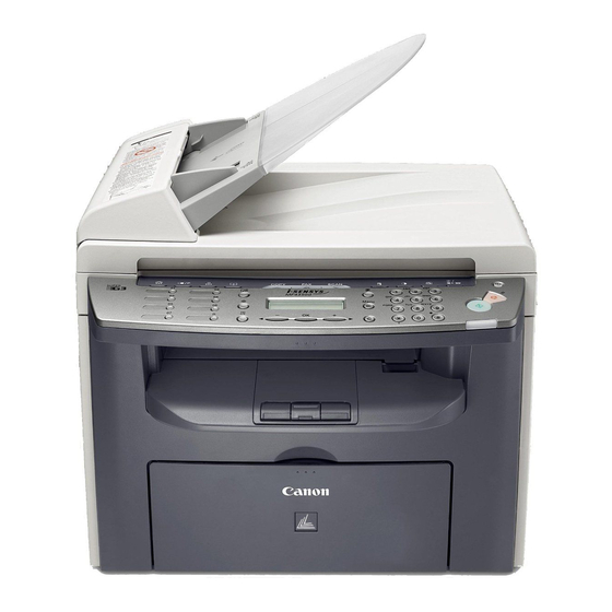
1.1.1 Names of Parts 1.1.1.1 External View 0020-2535 i-SENSYS MF4300dn / i-SENSYS MF4350d / i-SENSYS MF4380dn / i-SENSYS MF4310/4318 / i-SENSYS MF4320d / i-SENSYS MF4330d / i-SENSYS MF4340d / i-SENSYS D450d / i-SENSYS MF4370dn Front View (Body)(In the case of ADF) - Page 18 Chapter 1 Rear View (Body)(In the case of ADF) F-1-2 T-1-2 [1] USB port [5] External device jack [2] Rear cover [6] Handset jack [3] Power socket [7] Ethernet port [4] Telephone line jack Front View (Body)(In the case of DADF)
- Page 19 Chapter 1 [10] [11] [12] [13] [17] [16] [15] [14] F-1-3 T-1-3 [1] DADF (Duplex Automatic Document Feeder) [10] Platen glass [2] Slide Guides [11] Output tray extension [3] Document feeder tray [12] Paper stopper [4] Document delivery tray [13] Slide guides for multi-purpose tray [5] Operation panel [14] Paper guide rail [6] USB memory port...
-
Page 20: Section View (Host Machine)
[7] Ethernet port [4] Telephone line jack 1.1.1.2 Section View (Host Machine) 0020-2546 i-SENSYS MF4300dn / i-SENSYS MF4350d / i-SENSYS MF4380dn / i-SENSYS MF4310/4318 / i-SENSYS MF4320d / i-SENSYS MF4330d / i-SENSYS MF4340d / i-SENSYS D450d / i-SENSYS MF4370dn [14] [13]... -
Page 21: Section View (Adf/Dadf)
[14] fixing unit 1.1.1.3 Section View (ADF/DADF) 0020-2548 i-SENSYS MF4300dn / i-SENSYS MF4350d / i-SENSYS MF4380dn / i-SENSYS MF4310/4318 / i-SENSYS MF4320d / i-SENSYS MF4330d / i-SENSYS MF4340d / i-SENSYS D450d / i-SENSYS MF4370dn ADF Section view F-1-6 [1] registration roller... -
Page 22: Control Panel
Chapter 1 1.1.1.4 Control panel 0020-2549 i-SENSYS MF4300dn / i-SENSYS MF4350d / i-SENSYS MF4380dn / i-SENSYS MF4310/4318 / i-SENSYS MF4320d / i-SENSYS MF4330d / i-SENSYS MF4340d / i-SENSYS D450d / i-SENSYS MF4370dn [1] [2] [5] [6] [7] [8] [10] [11]... -
Page 23: Safety
1.1.2.1 Safety of the Host Machine's Laser Mechanism 0020-2550 i-SENSYS MF4300dn / i-SENSYS MF4350d / i-SENSYS MF4380dn / i-SENSYS MF4310/4318 / i-SENSYS MF4320d / i-SENSYS MF4330d / i-SENSYS MF4340d / i-SENSYS D450d / i-SENSYS MF4370dn Laser radiation can prove to be harmful to the human body. The host machine's laser scanning system is completely sealed by means of a protective housing and external covers so that its light will not leak outside the host machine as long as the host machine is used normally. -
Page 24: Handling Of The Laser Assembly
1.1.2.3 Handling of the Laser Assembly 0020-2552 i-SENSYS MF4300dn / i-SENSYS MF4350d / i-SENSYS MF4380dn / i-SENSYS MF4310/4318 / i-SENSYS MF4320d / i-SENSYS MF4330d / i-SENSYS MF4340d / i-SENSYS D450d / i-SENSYS MF4370dn When performing servicing work around the laser scanner unit of this machine, be sure not to insert a highly reflective tool such as a driver directly into the laser light path. -
Page 25: Product Specifications
Chapter 1 1.1.3 Product Specifications 1.1.3.1 Host Machine Specifications 0020-2556 i-SENSYS MF4300dn / i-SENSYS MF4350d / i-SENSYS MF4380dn / i-SENSYS MF4310/4318 / i-SENSYS MF4320d / i-SENSYS MF4330d / i-SENSYS MF4340d / i-SENSYS D450d / i-SENSYS MF4370dn Copyboard Fixed Body Desktop (ADF standard type:MF4130/MF4150 only) -
Page 26: Adf/Dadf Specifications
Weight Approximately 13.4kg (including toner cartridges) 1.1.3.2 ADF/DADF Specifications 0020-2557 i-SENSYS MF4300dn / i-SENSYS MF4350d / i-SENSYS MF4380dn / i-SENSYS MF4310/4318 / i-SENSYS MF4320d / i-SENSYS MF4330d / i-SENSYS MF4340d / i-SENSYS D450d / i-SENSYS MF4370dn Original orientation Face-up method... -
Page 27: Function List
1.1.4 Function List 1.1.4.1 Scanning Range (ADF/DADF) 0020-2559 i-SENSYS MF4300dn / i-SENSYS MF4350d / i-SENSYS MF4380dn / i-SENSYS MF4310/4318 / i-SENSYS MF4320d / i-SENSYS MF4330d / i-SENSYS MF4340d / i-SENSYS D450d / i-SENSYS MF4370dn F-1-12 [1] leading edge of original... -
Page 28: Recording Range (Copy)
2.0 +2.0/-2.0 mm 1.1.4.3 Recording Range (Copy) 0020-2561 i-SENSYS MF4300dn / i-SENSYS MF4350d / i-SENSYS MF4380dn / i-SENSYS MF4310/4318 / i-SENSYS MF4320d / i-SENSYS MF4330d / i-SENSYS MF4340d / i-SENSYS D450d / i-SENSYS MF4370dn F-1-14 [1] leading edge of document... -
Page 29: Recording Range (Reception)
5.0 +2.0/-2.0 mm 1.1.4.4 Recording Range (Reception) 0020-2562 i-SENSYS MF4300dn / i-SENSYS MF4350d / i-SENSYS MF4380dn / i-SENSYS MF4310/4318 / i-SENSYS MF4320d / i-SENSYS MF4330d / i-SENSYS MF4340d / i-SENSYS D450d / i-SENSYS MF4370dn F-1-15 [1] leading edge of document... -
Page 30: Operation Environment Of The Printer Driver
Chapter 1 F-1-16 [1] leading edge of document [6] trailing edge margin [2] left margin [7] non-scanning area [3] effective scanning width [8] scanning range [4] right margin [9] trailing edge of document [5] leading edge margin T-1-11 item Letter Legal left margin 5.0 +2.0/-2.0 mm... - Page 31 Chapter 1 Supported protocol TCP/IP Interface; Ethernet ll Supported OS (Print application) Windows2000, XP, Vista 1-15...
-
Page 33: Chapter 2 Basic Operation
Chapter 2 Basic Operation... - Page 35 Contents Contents 2.1 Construction ...................................2-1 2.1.1 Function Configuration ................................2-1 2.2 Basic Sequence ................................2-1 2.2.1 Basic Operation Sequence ................................2-1...
-
Page 37: Construction
2.1.1 Function Configuration 0020-2566 i-SENSYS MF4300dn / i-SENSYS MF4350d / i-SENSYS MF4380dn / i-SENSYS MF4310/4318 / i-SENSYS MF4320d / i-SENSYS MF4330d / i-SENSYS MF4340d / i-SENSYS D450d / i-SENSYS MF4370dn The functions of this host machine are mainly composed of the 7 blocks: System Control System, Scanning Control System, Printer Control System, Laser Scanner System, Image Formation System, Fixing System, Pickup/Feeding System. -
Page 39: Chapter 3 Original Exposure System
Chapter 3 Original Exposure System... - Page 41 Contents Contents 3.1 Basic Construction .................................3-1 3.1.1 Specifications / Control / Function List ............................3-1 3.1.2 Major Components..................................3-1 3.2 Parts Replacement Procedure............................3-3 3.2.1 Scanner Unit....................................3-3 3.2.1.1 Preparation for Removing the Scanner Unit ..............................3-3 3.2.1.2 Removing the Scanner Unit ....................................3-3 3.2.2 Reader Motor ....................................
-
Page 43: Basic Construction
Chapter 3 3.1 Basic Construction 3.1.1 Specifications / Control / Function List 0020-2574 i-SENSYS MF4300dn / i-SENSYS MF4350d / i-SENSYS MF4380dn / i-SENSYS MF4310/4318 / i-SENSYS MF4320d / i-SENSYS MF4330d / i-SENSYS MF4340d / i-SENSYS D450d / i-SENSYS MF4370dn T-3-1 item... - Page 44 Chapter 3 F-3-1...
-
Page 45: Parts Replacement Procedure
3.2.1 Scanner Unit 3.2.1.1 Preparation for Removing the Scanner Unit 0020-2576 i-SENSYS MF4300dn / i-SENSYS MF4350d / i-SENSYS MF4380dn / i- SENSYS MF4310/4318 / i-SENSYS MF4320d / i-SENSYS MF4330d / i- SENSYS MF4340d / i-SENSYS D450d / i-SENSYS MF4370dn 1) Remove the front cover.(page 9-2)Reference[Removing the Front Cov- 2) Remove the right cover.(page 9-2)Reference[Removing the Right Cov-... - Page 46 Chapter 3 F-3-9 In the case of DADF F-3-6 2) Reverse the copyboard [1] and detach the bottom cover [4]. In the case of ADF - 2 screws [2] - 5 claws [3] F-3-10 4) Remove the 4 screws and the 2 claws at the back of the control panel unit. F-3-7 In the case of DADF - 1 screws [2]...
-
Page 47: Contact Sensor
F-3-16 3.2.3 Contact Sensor 3.2.3.1 Removing the Contact Sensor 0020-2673 i-SENSYS MF4300dn / i-SENSYS MF4350d / i-SENSYS MF4380dn / i- SENSYS MF4310/4318 / i-SENSYS MF4320d / i-SENSYS MF4330d / i- SENSYS MF4340d / i-SENSYS D450d / i-SENSYS MF4370dn F-3-13 9) Remove the claw [1] to remove the gear [3] together with the belt [2]. - Page 48 Chapter 3 F-3-18 Points to Note at Attaching Be sure to fit the gear [1] of the belt with the gear [2] on the bottom surface of the contact sensor unit. 6) Disconnect the connector [1]. F-3-19 7) Turn the contact sensor [1] in the direction shown by the arrow, remove the 2 shafts [2], and then remove the contact sensor [1].
-
Page 49: Chapter 4 Original Feeding System
Chapter 4 Original Feeding System... - Page 51 Contents Contents 4.1 Basic Operation................................4-1 4.1.1 Basic Operation (ADF) ................................4-1 4.1.2 Basic Operation (DADF) ................................4-2 4.1.3 Original Detection..................................4-4 4.2 Detection Jams ................................4-5 4.2.1 Jam Detection....................................4-5 4.3 ADF/DADF..................................4-6 4.3.1 Pick-up Roller ....................................4-6 4.3.1.1 Removing the ADF Pickup Roller ..................................4-6 4.3.1.2 Removing the DADF Pickup Roller Unit ...............................4-6 4.3.2 ADF Motor....................................
-
Page 53: Basic Operation (Adf)
4.1.1 Basic Operation (ADF) 0020-2675 i-SENSYS MF4300dn / i-SENSYS MF4350d / i-SENSYS MF4380dn / i-SENSYS MF4310/4318 / i-SENSYS MF4320d / i-SENSYS MF4330d / i-SENSYS MF4340d / i-SENSYS D450d / i-SENSYS MF4370dn The Auto Document Feeder (ADF) mounted onto this host machine is dedicated to stream-reading. -
Page 54: Basic Operation (Dadf)
Chapter 4 4.1.2 Basic Operation (DADF) 0020-2905 i-SENSYS MF4300dn / i-SENSYS MF4350d / i-SENSYS MF4380dn / i-SENSYS MF4310/4318 / i-SENSYS MF4320d / i-SENSYS MF4330d / i-SENSYS MF4340d / i-SENSYS D450d / i-SENSYS MF4370dn Pickup/Feed/Delivery Operation The Auto Document Feeder (ADF) mounted onto this host machine is dedicated to stream-reading. - Page 55 Chapter 4 F-4-6...
-
Page 56: Original Detection
4.1.3 Original Detection 0020-2676 i-SENSYS MF4300dn / i-SENSYS MF4350d / i-SENSYS MF4380dn / i-SENSYS MF4310/4318 / i-SENSYS MF4320d / i-SENSYS MF4330d / i-SENSYS MF4340d / i-SENSYS D450d / i-SENSYS MF4370dn There are two types of original detection in this equipment. -
Page 57: Detection Jams
4.2 Detection Jams 4.2.1 Jam Detection 0020-2677 i-SENSYS MF4300dn / i-SENSYS MF4350d / i-SENSYS MF4380dn / i-SENSYS MF4310/4318 / i-SENSYS MF4320d / i-SENSYS MF4330d / i-SENSYS MF4340d / i-SENSYS D450d / i-SENSYS MF4370dn The following cases are judged as jam. -
Page 58: Adf/Dadf
4.3.1 Pick-up Roller 4.3.1.1 Removing the ADF Pickup Roller 0020-3069 i-SENSYS MF4300dn / i-SENSYS MF4350d / i-SENSYS MF4380dn / i- SENSYS MF4310/4318 / i-SENSYS MF4320d / i-SENSYS MF4330d / i- SENSYS MF4340d / i-SENSYS D450d / i-SENSYS MF4370dn 1) Remove the shaft [1] with a screwdriver to remove the ADF pickup unit [2]. - Page 59 Chapter 4 F-4-14 2) Remove the DADF upper cover [1]. - 2 bosses [1] F-4-16 Points to Note when Attaching Match the gear [1] with the D cut surface of the DADF pickup roller shaft [2]. 4) Remove two E-rings [1], one shaft support [2], and one shaft support [3]. F-4-17 5) Move the DADF separation roller unit [1] to the direction shown by an ar- row, and remove it from the DADF upper cover.
-
Page 60: Adf Motor
4.3.2 ADF Motor 4.3.2.1 Preparation for Removing the ADF/DADF Motor 0020-2679 i-SENSYS MF4300dn / i-SENSYS MF4350d / i-SENSYS MF4380dn / i- SENSYS MF4310/4318 / i-SENSYS MF4320d / i-SENSYS MF4330d / i- SENSYS MF4340d / i-SENSYS D450d / i-SENSYS MF4370dn 1) Remove the front cover.(page 9-2)Reference[Removing the Front Cov- 2) Remove the right cover.(page 9-2)Reference[Removing the Right Cov-... -
Page 61: Removing The Dadf Motor
4.3.2.3 Removing the DADF Motor F-4-28 0020-2680 i-SENSYS MF4300dn / i-SENSYS MF4350d / i-SENSYS MF4380dn / i- 4) Remove the cover [1] in the direction shown by an arrow. SENSYS MF4310/4318 / i-SENSYS MF4320d / i-SENSYS MF4330d / i- - 1 hook [2] SENSYS MF4340d / i-SENSYS D450d / i-SENSYS MF4370dn 1) Open the copyboard cover unit [1] and remove it in an upward direction. - Page 62 Chapter 4 F-4-31 7) Turn down the hinge [1]. F-4-29 5) Remove the hook [2] from the copyboard pickup tray [1]. - 1 claw [3] F-4-32 8) Remove the cover [2] in the direction shown by an arrow. - 1 boss [1] F-4-30 6) Remove the document pickup tray [1] in the direction shown by an arrow.
- Page 63 Chapter 4 F-4-33 9) Remove the cable [2]. - 2 clamps [1] F-4-35 11) Close the ADF cover [1]. F-4-36 12) Remove the ADF unit [1] in the direction shown by an arrow. F-4-34 10) Remove five screws [1]. F-4-37 13) Remove the connector [1].
-
Page 64: Separation Pad
F-4-39 4.3.3 Separation Pad 4.3.3.1 Removing the ADF Separation Pad 0020-3070 i-SENSYS MF4300dn / i-SENSYS MF4350d / i-SENSYS MF4380dn / i- 4.3.3.2 Removing the DADF Separation Pad SENSYS MF4310/4318 / i-SENSYS MF4320d / i-SENSYS MF4330d / i- 0020-2681 i-SENSYS MF4300dn / i-SENSYS MF4350d / i-SENSYS MF4380dn / i-... - Page 65 Chapter 4 F-4-43 3) Remove two screws [1]. Hold the protrusion [2] and remove the separa- tion pad cover [3]. F-4-44 4) Move the separation pad [1] in the direction shown by an arrow [A] and then move it in the direction shown by an arrow [B]. F-4-45 Points to Note when Attaching Insert the spring [1] of the separation pad into the boss [2].
-
Page 67: Chapter 5 Laser Exposure
Chapter 5 Laser Exposure... - Page 69 Contents Contents 5.1 Overview/Configuration ..............................5-1 5.1.1 Overview...................................... 5-1 5.2 Controlling the Laser Activation Timing........................5-2 5.2.1 Laser ON / OFF Control ................................5-2 5.3 Controlling the Intensity of Laser Light ........................5-2 5.3.1 Auto Photoelectric Current Control (APC)..........................5-2 5.4 Controlling the Laser Scanner Motor..........................5-4 5.4.1 Overview......................................
-
Page 71: Overview/Configuration
Chapter 5 5.1 Overview/Configuration 5.1.1 Overview 0020-2682 i-SENSYS MF4300dn / i-SENSYS MF4350d / i-SENSYS MF4380dn / i-SENSYS MF4310/4318 / i-SENSYS MF4320d / i-SENSYS MF4330d / i-SENSYS MF4340d / i-SENSYS D450d / i-SENSYS MF4370dn F-5-1 [1] Laser driver PCB [5] Scanner motor... -
Page 72: Controlling The Laser Activation Timing
5.2.1 Laser ON / OFF Control 0020-2683 i-SENSYS MF4300dn / i-SENSYS MF4350d / i-SENSYS MF4380dn / i-SENSYS MF4310/4318 / i-SENSYS MF4320d / i-SENSYS MF4330d / i-SENSYS MF4340d / i-SENSYS D450d / i-SENSYS MF4370dn This is the control where the laser driver turns on / off the laser diode (LD) based on the laser control signal sent from the DCNT PCB. - Page 73 Chapter 5...
-
Page 74: Controlling The Laser Scanner Motor
5.4.1 Overview 0020-2686 i-SENSYS MF4300dn / i-SENSYS MF4350d / i-SENSYS MF4380dn / i-SENSYS MF4310/4318 / i-SENSYS MF4320d / i-SENSYS MF4330d / i-SENSYS MF4340d / i-SENSYS D450d / i-SENSYS MF4370dn This is the control to rotate the scanner motor at constant speed. -
Page 75: Parts Replacement Procedure
5.5.1 Laser/Scanner Unit 5.5.1.1 Preparation for Removing the Laser Scanner Unit 0020-2689 i-SENSYS MF4300dn / i-SENSYS MF4350d / i-SENSYS MF4380dn / i- SENSYS MF4310/4318 / i-SENSYS MF4320d / i-SENSYS MF4330d / i- SENSYS MF4340d / i-SENSYS D450d / i-SENSYS MF4370dn 1) Remove the front cover.(page 9-2)Reference[Removing the Front Cov-... -
Page 77: Chapter 6 Image Formation
Chapter 6 Image Formation... - Page 79 Contents Contents 6.1 Overview/Configuration ..............................6-1 6.1.1 Configuration ....................................6-1 6.1.2 Print Process....................................6-1 6.2 Driving and Controlling the High-Voltage System .......................6-2 6.2.1 Generation of Transfer Charging Bias ............................6-2 6.3 Toner Cartridge ................................6-3 6.3.1 Toner Level Detection ................................. 6-3 6.4 Parts Replacement Procedure............................6-4 6.4.1 Transfer Charging Roller ................................
-
Page 81: Overview/Configuration
6.1.1 Configuration 0020-2691 i-SENSYS MF4300dn / i-SENSYS MF4350d / i-SENSYS MF4380dn / i-SENSYS MF4310/4318 / i-SENSYS MF4320d / i-SENSYS MF4330d / i-SENSYS MF4340d / i-SENSYS D450d / i-SENSYS MF4370dn The image forming system is the core part of this machine, and is composed of the cartridge, the transfer charging roller, the fixing assembly, etc. -
Page 82: Driving And Controlling The High-Voltage System
6.2.1 Generation of Transfer Charging Bias 0020-2693 i-SENSYS MF4300dn / i-SENSYS MF4350d / i-SENSYS MF4380dn / i-SENSYS MF4310/4318 / i-SENSYS MF4320d / i-SENSYS MF4330d / i-SENSYS MF4340d / i-SENSYS D450d / i-SENSYS MF4370dn The transfer charging bias (TRS) is output to transfer the toner on the photosensitive drum to papers. -
Page 83: Toner Cartridge
6.3 Toner Cartridge 6.3.1 Toner Level Detection 0020-2694 i-SENSYS MF4300dn / i-SENSYS MF4350d / i-SENSYS MF4380dn / i-SENSYS MF4310/4318 / i-SENSYS MF4320d / i-SENSYS MF4330d / i-SENSYS MF4340d / i-SENSYS D450d / i-SENSYS MF4370dn Overview The toner sensor (magnetic sensor) detects the remaining toner level. -
Page 84: Parts Replacement Procedure
6.4.1 Transfer Charging Roller 6.4.1.1 Removing the Transfer Charging Roller 0020-2695 i-SENSYS MF4300dn / i-SENSYS MF4350d / i-SENSYS MF4380dn / i- SENSYS MF4310/4318 / i-SENSYS MF4320d / i-SENSYS MF4330d / i- SENSYS MF4340d / i-SENSYS D450d / i-SENSYS MF4370dn 1) Open the control panel assembly [1]. -
Page 85: Chapter 7 Pickup And Feed System
Chapter 7 Pickup and Feed System... - Page 87 Contents Contents 7.1 Overview/Configuration ..............................7-1 7.1.1 Overview...................................... 7-1 7.2 Other Control .................................7-2 7.2.1 Overview...................................... 7-2 7.3 Detection Jams ................................7-3 7.3.1 Jam Detection Outline.................................. 7-3 7.3.1.1 Overview .........................................7-3 7.3.2 Delay Jams ....................................7-3 7.3.2.1 Pickup Delay Jam......................................7-3 7.3.2.2 Delivery Delay Jam......................................7-3 7.3.3 Stationary Jams ....................................
-
Page 89: Overview/Configuration
7.1.1 Overview 0020-2696 i-SENSYS MF4300dn / i-SENSYS MF4350d / i-SENSYS MF4380dn / i-SENSYS MF4310/4318 / i-SENSYS MF4320d / i-SENSYS MF4330d / i-SENSYS MF4340d / i-SENSYS D450d / i-SENSYS MF4370dn The pickup/feeding system is the part to pickup and feed a paper, and it is composed of the main motor, solenoid, and various motors. -
Page 90: Other Control
7.2 Other Control 7.2.1 Overview 0020-2697 i-SENSYS MF4300dn / i-SENSYS MF4350d / i-SENSYS MF4380dn / i-SENSYS MF4310/4318 / i-SENSYS MF4320d / i-SENSYS MF4330d / i-SENSYS MF4340d / i-SENSYS D450d / i-SENSYS MF4370dn Pickup/Feed Operation The pickup/feed assembly is the mechanism to pickup and feed paper one at a time from the pickup tray or the manual feed tray. -
Page 91: Detection Jams
7.3.1.1 Overview 0020-2698 i-SENSYS MF4300dn / i-SENSYS MF4350d / i-SENSYS MF4380dn / i-SENSYS MF4310/4318 / i-SENSYS MF4320d / i-SENSYS MF4330d / i-SENSYS MF4340d / i-SENSYS D450d / i-SENSYS MF4370dn The machine has the following paper sensors to detect the presence/absence of paper at the time of startup, opening the door, or feeding a paper, as well as to detect whether a paper is fed normally. -
Page 92: Wrapping Jam
7.3.4.2 Wrapping Jam 0020-2705 i-SENSYS MF4300dn / i-SENSYS MF4350d / i-SENSYS MF4380dn / i-SENSYS MF4310/4318 / i-SENSYS MF4320d / i-SENSYS MF4330d / i-SENSYS MF4340d / i-SENSYS D450d / i-SENSYS MF4370dn CPU executes the wrapping jam detection after it judges there is no delivery delay jam present. -
Page 93: Residual Jam At Startup
7.3.4.3 Residual Jam at Startup 0020-2706 i-SENSYS MF4300dn / i-SENSYS MF4350d / i-SENSYS MF4380dn / i-SENSYS MF4310/4318 / i-SENSYS MF4320d / i-SENSYS MF4330d / i-SENSYS MF4340d / i-SENSYS D450d / i-SENSYS MF4370dn If the sensor (leading edge sensor (PS801) or delivery sensor (PS803), or delivery paper width sensor (PS804)) detects a paper at the start of initial rotation, CPU judges as the residual jam at startup. -
Page 94: Duplex Unit
7.4.1 Overview 0020-2707 i-SENSYS MF4300dn / i-SENSYS MF4350d / i-SENSYS MF4380dn / i-SENSYS MF4310/4318 / i-SENSYS MF4320d / i-SENSYS MF4330d / i-SENSYS MF4340d / i-SENSYS D450d / i-SENSYS MF4370dn The duplexing pick up operation of this machine is performed by the drive of the main motor (M1) under CPU control of the DCNT PCB. -
Page 95: Parts Replacement Procedure
7.5 Parts Replacement Procedure 7.5.3.1 Removing Pickup Roller 0020-2713 i-SENSYS MF4300dn / i-SENSYS MF4350d / i-SENSYS MF4380dn / i- 7.5.1 Main Motor SENSYS MF4310/4318 / i-SENSYS MF4320d / i-SENSYS MF4330d / i- SENSYS MF4340d / i-SENSYS D450d / i-SENSYS MF4370dn 7.5.1.1 Preparation for Removing Main Motor... -
Page 97: Chapter 8 Fixing System
Chapter 8 Fixing System... - Page 99 Contents Contents 8.1 Overview/Configuration ..............................8-1 8.1.1 Specification/Control/Function List............................. 8-1 8.1.2 Overview...................................... 8-1 8.2 Various Control Mechanisms............................8-3 8.2.1 Controlling the Temperature of the Fixing Unit .......................... 8-3 8.2.1.1 Fixing Temperature Control....................................8-3 8.3 Protection Function ................................8-4 8.3.1 Protection Function ..................................8-4 8.4 Parts Replacement Procedure............................8-6 8.4.1 Fixing Unit ....................................
-
Page 101: Overview/Configuration
Chapter 8 8.1 Overview/Configuration 8.1.1 Specification/Control/Function List 0020-2714 i-SENSYS MF4300dn / i-SENSYS MF4350d / i-SENSYS MF4380dn / i-SENSYS MF4310/4318 / i-SENSYS MF4320d / i-SENSYS MF4330d / i-SENSYS MF4340d / i-SENSYS D450d / i-SENSYS MF4370dn T-8-1 Item Function/Method Fixing method On-demand fixing... - Page 102 Chapter 8 F-8-2 [1] Pressure roller [2] Fixing film H1: Fixing heater TH1: Thermistor TP1: Temperature fuse...
-
Page 103: Various Control Mechanisms
8.2.1.1 Fixing Temperature Control 0020-2716 i-SENSYS MF4300dn / i-SENSYS MF4350d / i-SENSYS MF4380dn / i-SENSYS MF4310/4318 / i-SENSYS MF4320d / i-SENSYS MF4330d / i-SENSYS MF4340d / i-SENSYS D450d / i-SENSYS MF4370dn With this control, the surface temperature of the fixing heater is detected, and also the drive signal of the fixing heater is controlled to maintain the target temperature of the fixing heater. -
Page 104: Protection Function
8.3.1 Protection Function 0020-2717 i-SENSYS MF4300dn / i-SENSYS MF4350d / i-SENSYS MF4380dn / i-SENSYS MF4310/4318 / i-SENSYS MF4320d / i-SENSYS MF4330d / i-SENSYS MF4340d / i-SENSYS D450d / i-SENSYS MF4370dn In order to prevent the fixing heater runaway, the machine has the following 3 protection functions. - Page 105 Chapter 8 Failure of fixing assembly Thermistor temperature Heater temperature detection time During normal temperature control Less than 100 deg C 1.2 sec in a row During temperature control at sheet-to-sheet interval, during cleaning mode Less than 55 deg C 1.2 sec in a row After the thermistor temperature exceeds 50 deg C Less than 20 deg C...
-
Page 106: Parts Replacement Procedure
8.4.1 Fixing Unit 8.4.1.1 Preparation for Removing Fixing Assembly 0020-2718 i-SENSYS MF4300dn / i-SENSYS MF4350d / i-SENSYS MF4380dn / i- SENSYS MF4310/4318 / i-SENSYS MF4320d / i-SENSYS MF4330d / i- SENSYS MF4340d / i-SENSYS D450d / i-SENSYS MF4370dn 1) Remove the front cover.(page 9-2)Reference[Removing the Front Cov- 2) Remove the right cover.(page 9-2)Reference[Removing the Right Cov-... -
Page 107: Removing Fixing Film Unit
Assembly] 8.4.2.2 Removing Fixing Film Unit 0020-2721 i-SENSYS MF4300dn / i-SENSYS MF4350d / i-SENSYS MF4380dn / i- SENSYS MF4310/4318 / i-SENSYS MF4320d / i-SENSYS MF4330d / i- SENSYS MF4340d / i-SENSYS D450d / i-SENSYS MF4370dn 1) Free the cable [1] from the 4 cable guides [2]. -
Page 109: Chapter 9 External And Controls
Chapter 9 External and Controls... - Page 111 Contents Contents 9.1 Control Panel..................................9-1 9.1.1 Outline......................................9-1 9.2 Power Supply .................................9-1 9.2.1 Power Supply ....................................9-1 9.2.1.1 Power Supply Route......................................9-1 9.2.2 Protection Function ..................................9-1 9.2.2.1 Protecting Function ......................................9-1 9.3 Parts Replacement Procedure............................9-2 9.3.1 Front Cover ....................................9-2 9.3.1.1 Removing the Front Cover....................................9-2 9.3.2 Rear Cover ....................................
-
Page 113: Control Panel
9.1.1 Outline 0020-2722 i-SENSYS MF4300dn / i-SENSYS MF4350d / i-SENSYS MF4380dn / i-SENSYS MF4310/4318 / i-SENSYS MF4320d / i-SENSYS MF4330d / i-SENSYS MF4340d / i-SENSYS D450d / i-SENSYS MF4370dn The machine's control panel consists of the following PCBs, and is controlled by the SCNT PCB. -
Page 114: Parts Replacement Procedure
9.3.1 Front Cover 9.3.1.1 Removing the Front Cover 0020-2724 i-SENSYS MF4300dn / i-SENSYS MF4350d / i-SENSYS MF4380dn / i- SENSYS MF4310/4318 / i-SENSYS MF4320d / i-SENSYS MF4330d / i- SENSYS MF4340d / i-SENSYS D450d / i-SENSYS MF4370dn 1) Remove the paper cassette [1]. -
Page 115: Left Cover
The scanner unit cannot be secured if the damper is removed. Be careful not 0020-2728 i-SENSYS MF4300dn / i-SENSYS MF4350d / i-SENSYS MF4380dn / i- to get your hands caught because you have to perform the work with the SENSYS MF4310/4318 / i-SENSYS MF4320d / i-SENSYS MF4330d / i- control panel open from now onward. -
Page 116: Upper Cover
Unit] 9.3.6.2 Removing the Printer Cover 0020-2732 i-SENSYS MF4300dn / i-SENSYS MF4350d / i-SENSYS MF4380dn / i- SENSYS MF4310/4318 / i-SENSYS MF4320d / i-SENSYS MF4330d / i- SENSYS MF4340d / i-SENSYS D450d / i-SENSYS MF4370dn 1) Open the printer cover [1]. -
Page 117: Scnt Board
9.3.8.3 Actions At Replacing the SCNT PCB F-9-18 0020-2736 i-SENSYS MF4300dn / i-SENSYS MF4350d / i-SENSYS MF4380dn / i- SENSYS MF4310/4318 / i-SENSYS MF4320d / i-SENSYS MF4330d / i- 9.3.8 SCNT Board SENSYS MF4340d / i-SENSYS D450d / i-SENSYS MF4370dn 9.3.8.1 Preparation for Removing the SCNT PCB... -
Page 118: Dcnt Board
9.3.9.1 Preparation for Removing the DCNT PCB F-9-23 0020-2737 i-SENSYS MF4300dn / i-SENSYS MF4350d / i-SENSYS MF4380dn / i- SENSYS MF4310/4318 / i-SENSYS MF4320d / i-SENSYS MF4330d / i- SENSYS MF4340d / i-SENSYS D450d / i-SENSYS MF4370dn Points to Note When Attaching Make sure to insert the shutter arm [4] through the hole [5] of the scanner 1) Remove the front cover.(page 9-2)Reference[Removing the Front Cov-... -
Page 119: Power Supply Pcb
9.3.10 Power Supply PCB 9.3.10.1 Preparation for Removing the Power Supply 0020-2739 i-SENSYS MF4300dn / i-SENSYS MF4350d / i-SENSYS MF4380dn / i- SENSYS MF4310/4318 / i-SENSYS MF4320d / i-SENSYS MF4330d / i- SENSYS MF4340d / i-SENSYS D450d / i-SENSYS MF4370dn 1) Remove the front cover.(page 9-2)Reference[Removing the Front Cov-... -
Page 120: Removing The High Voltage Pcb
Power Supply PCB] 9.3.11.2 Removing the High Voltage PCB 0020-2742 i-SENSYS MF4300dn / i-SENSYS MF4350d / i-SENSYS MF4380dn / i- SENSYS MF4310/4318 / i-SENSYS MF4320d / i-SENSYS MF4330d / i- SENSYS MF4340d / i-SENSYS D450d / i-SENSYS MF4370dn 1) Remove the 2 claws [1] to remove the fixing guide [2]. -
Page 121: Chapter 10 Maintenance And Inspection
Chapter 10 Maintenance and Inspection... -
Page 123: Periodically Replaced Parts
Contents Contents 10.1 Periodically Replaced Parts ............................10-1 10.1.1 Periodically Replaced Parts ..............................10-1 10.2 Periodical Service ..............................10-1 10.2.1 Periodically Service Items ............................... 10-1 10.3 Cleaning ..................................10-1 10.3.1 Cleaning Items ..................................10-1 10.3.2 Cleaning Method (External Covers) ............................10-1 10.3.3 Cleaning Method (Reader Unit)............................... 10-2 10.3.4 Cleaning Method (Pressure Roller) ............................ -
Page 125: Periodically Replaced Parts
10.1.1 Periodically Replaced Parts 0020-2745 i-SENSYS MF4300dn / i-SENSYS MF4350d / i-SENSYS MF4380dn / i-SENSYS MF4310/4318 / i-SENSYS MF4320d / i-SENSYS MF4330d / i-SENSYS MF4340d / i-SENSYS D450d / i-SENSYS MF4370dn There are no periodically replaced parts with this machine. -
Page 126: Cleaning Method (Reader Unit)
Chapter 10 10.3.3 Cleaning Method (Reader Unit) 0020-2749 i-SENSYS MF4300dn / i-SENSYS MF4350d / i-SENSYS MF4380dn / i-SENSYS MF4310/4318 / i-SENSYS MF4320d / i-SENSYS MF4330d / i-SENSYS MF4340d / i-SENSYS D450d / i-SENSYS MF4370dn In the case of ADF F-10-1 [1] Document pickup roller Open the ADF and wipe off the smudge with the soft dry cloth. -
Page 127: Cleaning Method (Pressure Roller)
Open the copyboard cover and wipe off the smudge with the soft dry cloth. 10.3.4 Cleaning Method (Pressure Roller) 0020-2750 i-SENSYS MF4300dn / i-SENSYS MF4350d / i-SENSYS MF4380dn / i-SENSYS MF4310/4318 / i-SENSYS MF4320d / i-SENSYS MF4330d / i-SENSYS MF4340d / i-SENSYS D450d / i-SENSYS MF4370dn MEMO: Cleaning the roller takes approximately 130 seconds. -
Page 129: Chapter 11 Measurement And Adjustments
Chapter 11 Measurement and Adjustments... -
Page 131: Basic Adjustments
Contents Contents 11.1 Basic Adjustments..............................11-1 11.1.1 Paper Margin Adjustment ................................ 11-1 11.1.2 Reading Adjustment................................. 11-1 11.1.3 Print Adjustment ..................................11-2... -
Page 133: Basic Adjustments
Contents 11.1.1 Paper Margin Adjustment 0020-2751 -30 (-3.0 mm) i-SENSYS MF4300dn / i-SENSYS MF4350d / i-SENSYS MF4380dn / i- SENSYS MF4310/4318 / i-SENSYS MF4320d / i-SENSYS MF4330d / i- SENSYS MF4340d / i-SENSYS D450d / i-SENSYS MF4370dn -29 (-2.9 mm) -
Page 134: Print Adjustment
(0 to 4mm) 11.1.3 Print Adjustment 0020-2753 i-SENSYS MF4300dn / i-SENSYS MF4350d / i-SENSYS MF4380dn / i- SENSYS MF4310/4318 / i-SENSYS MF4320d / i-SENSYS MF4330d / i- SENSYS MF4340d / i-SENSYS D450d / i-SENSYS MF4370dn After pressing the 'Additional Functions' button and '#' button, select 'AD- JUST', and then, press 'OK' button. -
Page 135: Chapter 12 Correcting Faulty Images
Chapter 12 Correcting Faulty Images... - Page 137 Contents Contents 12.1 Outline of Electrical Components..........................12-1 12.1.1 Clutch/Solenoid/Motor/Fan ..............................12-1 12.1.1.1 List of Solenoids/Motors.....................................12-1 12.1.2 Sensor....................................... 12-3 12.1.2.1 List of Sensors......................................12-3 12.1.3 PCBs ......................................12-5 12.1.3.1 List of PCBs ........................................12-5...
-
Page 139: Outline Of Electrical Components
12.1 Outline of Electrical Components 12.1.1 Clutch/Solenoid/Motor/Fan 12.1.1.1 List of Solenoids/Motors 0020-2754 i-SENSYS MF4300dn / i-SENSYS MF4350d / i-SENSYS MF4380dn / i-SENSYS MF4310/4318 / i-SENSYS MF4320d / i-SENSYS MF4330d / i-SENSYS MF4340d / i-SENSYS D450d / i-SENSYS MF4370dn In the case of ADF F-12-1... - Page 140 Chapter 12 Symbol Name Main motor Reader motor ADF motor Cassette pickup solenoid Duplexing drive solenoid Reverse solenoid 12-2...
-
Page 141: Sensor
Chapter 12 12.1.2 Sensor 12.1.2.1 List of Sensors 0020-2755 i-SENSYS MF4300dn / i-SENSYS MF4350d / i-SENSYS MF4380dn / i-SENSYS MF4310/4318 / i-SENSYS MF4320d / i-SENSYS MF4330d / i-SENSYS MF4340d / i-SENSYS D450d / i-SENSYS MF4370dn In the case of ADF PS804... - Page 142 Chapter 12 PS804 PS106 PS105 PS803 PS801 PS805 TS101 F-12-4 Symbol Name PS105 DES sensor PS106 DS sensor PS801 leading edge sensor PS802 Paper width/cartridge detect sensor PS803 delivery sensor PS804 delivery paper width sensor PS805 Multi-purpose pickup sensor TS101 Toner level sensor 12-4...
-
Page 143: Pcbs
Chapter 12 12.1.3 PCBs 12.1.3.1 List of PCBs 0020-2756 i-SENSYS MF4300dn / i-SENSYS MF4350d / i-SENSYS MF4380dn / i-SENSYS MF4310/4318 / i-SENSYS MF4320d / i-SENSYS MF4330d / i-SENSYS MF4340d / i-SENSYS D450d / i-SENSYS MF4370dn In the case of ADF SW301... - Page 144 Chapter 12 DCNT PCB Power supply PCB High voltage PCB SW301 Interlock switch 12-6...
-
Page 145: Error Code
Chapter 13 Error Code... -
Page 147: Error Code Outline
Contents Contents 13.1 Error Code..................................13-1 13.1.1 Error Code Outline................................... 13-1 13.1.2 Error Code....................................13-1... -
Page 149: Error Code Outline
13.1.1 Error Code Outline 0020-2757 i-SENSYS MF4300dn / i-SENSYS MF4350d / i-SENSYS MF4380dn / i-SENSYS MF4310/4318 / i-SENSYS MF4320d / i-SENSYS MF4330d / i-SENSYS MF4340d / i-SENSYS D450d / i-SENSYS MF4370dn An error code is used to indicate a fault in a machine, and is indicated in the machine's LCD, showing the nature (symptoms) of the fault. Using the error code, the service man can readily find out how to correct the fault by simply referring to the service manual. - Page 150 Chapter 13 Error Code Description 0016 Receive DCN signal after sending PTT signal. 0017 Can't receive any response from remote side after sending DIS 0018 Can't detect energy within 6 sec after sending FTT command 0019 Received DCN signal sending CFR signal 001A No energy on line over 6 sec.
- Page 151 Chapter 13 Error Code Description 0069 Capability no match paper size after received is DCS signal. 0070 User press stop key within receiving. 0071 Memory full within receiving. 0080 Can't detect any G3 signal within 35 sec. specified by ITU-T in phase B. 0081 Received DTC signal in transmission phase.
- Page 152 Chapter 13 Error Code Description 00CF Received incorrect signal after sending DTC signal for V.34 polling. 00D0 Received ERR signal after sending EOR_NULL. 00D1 Received incorrect response after sending PPS_EOP signal 00D2 Received DCN after sending PPS_EOP signal 00D3 Received DCN after sending PPS_NULL signal 00D8 Can't detect correct phase 3 signal for poling.
-
Page 153: Chapter 14 Service Mode
Chapter 14 Service Mode... - Page 155 Contents Contents 14.1 Outline..................................14-1 14.1.1 Setting Service Data................................. 14-1 14.1.2 How to Activate Service Mode..............................14-1 14.1.3 Service Data Menu................................... 14-2 14.2 Service Soft Switch Settings (SSSW) ........................14-4 14.2.1 Outline...................................... 14-4 14.2.1.1 SOFT SWITCH Explained ..................................14-4 14.2.2 SSSW-SW02:................................... 14-6 14.2.2.1 Function List .......................................14-6 14.2.2.2 Bit 2 and 3 Elaborated....................................14-6 14.2.2.3 Bit 5 Elaborated......................................14-6 14.2.3 SSSW-SW04....................................
- Page 156 Contents 14.3.2.3 Sensor test ......................................... 14-16 14.3.2.4 Key test ........................................14-16...
-
Page 157: Setting Service Data
14.1.1 Setting Service Data 0020-2759 i-SENSYS MF4300dn / i-SENSYS MF4350d / i-SENSYS MF4380dn / i-SENSYS MF4310/4318 / i-SENSYS MF4320d / i-SENSYS MF4330d / i-SENSYS MF4340d / i-SENSYS D450d / i-SENSYS MF4370dn Service Mode contains the following service data items. Each service data can be viewed or modified using the menu items displayed on the screen. -
Page 158: Service Data Menu
Chapter 14 14.1.3 Service Data Menu 0020-2761 i-SENSYS MF4300dn / i-SENSYS MF4350d / i-SENSYS MF4380dn / i-SENSYS MF4310/4318 / i-SENSYS MF4320d / i-SENSYS MF4330d / i-SENSYS MF4340d / i-SENSYS D450d / i-SENSYS MF4370dn Service menu SERVICE CHOISE COUNTRY/REGION HUNGARY CODE... - Page 159 Chapter 14 ADJUST CIS ADJUST SHIPPING POS. HOME POS. SHEET POS. READING ADJUST BOOK MAIN REGIST BOOK SUB REGIST ADF MAIN REGIST ADF SUB REGIST-DES ADF SUB REGIST-COPY ADF SUB REGIST-SFINE ADF SUB REGIST-FINE ADF SUB REGIST-STD ADF SUB ZOOM-COPY ADF SUB ZOOM-SFINE ADF SUB ZOOM-FINE ADF SUB ZOOM-STD...
-
Page 160: Service Soft Switch Settings (Sssw)
14.2.1.1 SOFT SWITCH Explained 0020-2762 i-SENSYS MF4300dn / i-SENSYS MF4350d / i-SENSYS MF4380dn / i-SENSYS MF4310/4318 / i-SENSYS MF4320d / i-SENSYS MF4330d / i-SENSYS MF4340d / i-SENSYS D450d / i-SENSYS MF4370dn Each entry / setting item of SOFT SWITCH consists of 8 bitswitches. Each bitswitch displayed on the screen has an assigned number as shown in the figure below. - Page 161 Chapter 14 Each Bit has a value - either 0 or 1. SW01 F-14-6 Shown below is what each number and data indicates in the bitswitch table. Indicates the set value is '0.' Indicates the set value is '1.' Function Indicates this is the default setting.
-
Page 162: Sssw-Sw02
Chapter 14 14.2.2 SSSW-SW02: 14.2.2.1 Function List 0020-2763 i-SENSYS MF4300dn / i-SENSYS MF4350d / i-SENSYS MF4380dn / i-SENSYS MF4310/4318 / i-SENSYS MF4320d / i-SENSYS MF4330d / i-SENSYS MF4340d / i-SENSYS D450d / i-SENSYS MF4370dn T-14-1 Function Not in Use RTN Transmission Condition... -
Page 163: Bit 8 Elaborated
14.2.3.2 Bit 8 Elaborated 0020-2767 i-SENSYS MF4300dn / i-SENSYS MF4350d / i-SENSYS MF4380dn / i-SENSYS MF4310/4318 / i-SENSYS MF4320d / i-SENSYS MF4330d / i-SENSYS MF4340d / i-SENSYS D450d / i-SENSYS MF4370dn An alarm can be set to go off when the transmission has been completed without a problem. Change the setting to ON in order to activate this alarm. -
Page 164: Bit 1 Elaborated
14.2.4.2 Bit 1 Elaborated 0020-2769 i-SENSYS MF4300dn / i-SENSYS MF4350d / i-SENSYS MF4380dn / i-SENSYS MF4310/4318 / i-SENSYS MF4320d / i-SENSYS MF4330d / i-SENSYS MF4340d / i-SENSYS D450d / i-SENSYS MF4370dn An alarm goes off when the transmission has been terminated due to some error. Change the setting to OFF in order to make this alarm inactive. -
Page 165: Sssw-Sw21
(1, 1, 1) 11 sec 14.2.7 SSSW-SW21 14.2.7.1 Function List 0020-2775 i-SENSYS MF4300dn / i-SENSYS MF4350d / i-SENSYS MF4380dn / i-SENSYS MF4310/4318 / i-SENSYS MF4320d / i-SENSYS MF4330d / i-SENSYS MF4340d / i-SENSYS D450d / i-SENSYS MF4370dn T-14-7 Function Not in Use... -
Page 166: Bit5Åa6Çãè⁄Çþ
Chapter 14 14.2.8.2 Bit5ÅA6ÇÃè⁄çÞ 0020-2778 i-SENSYS MF4300dn / i-SENSYS MF4350d / i-SENSYS MF4380dn / i-SENSYS MF4310/4318 / i-SENSYS MF4320d / i-SENSYS MF4330d / i-SENSYS MF4340d / i-SENSYS D450d / i-SENSYS MF4370dn Bit5ÇýBit6ÇÃëgÇ›çáÇÌǼDžÇÊÇËÅAà»â½ÇÃÇÊǧDžǻÇÈÅB (Bit5, Bit6)= (0, 0) 200 msec (1, 0) 500 msec (0, 1) 1 sec (1, 1) 1.5 sec... -
Page 167: Bit 7 And 8 Elaborated
14.2.9.2 Bit 7 and 8 Elaborated 0020-2781 i-SENSYS MF4300dn / i-SENSYS MF4350d / i-SENSYS MF4380dn / i-SENSYS MF4310/4318 / i-SENSYS MF4320d / i-SENSYS MF4330d / i-SENSYS MF4340d / i-SENSYS D450d / i-SENSYS MF4370dn Enables to set the duration of pause. -
Page 168: Sssw-Sw39
(0, 0, 1) 2400 14.2.11 SSSW-SW39 14.2.11.1 Function List 0020-2784 i-SENSYS MF4300dn / i-SENSYS MF4350d / i-SENSYS MF4380dn / i-SENSYS MF4310/4318 / i-SENSYS MF4320d / i-SENSYS MF4330d / i-SENSYS MF4340d / i-SENSYS D450d / i-SENSYS MF4370dn T-14-14 Function Not in Use... -
Page 169: Bit 8 Elaborated
14.2.11.3 Bit 8 Elaborated 0020-2786 i-SENSYS MF4300dn / i-SENSYS MF4350d / i-SENSYS MF4380dn / i-SENSYS MF4310/4318 / i-SENSYS MF4320d / i-SENSYS MF4330d / i-SENSYS MF4340d / i-SENSYS D450d / i-SENSYS MF4370dn Enables to choose whether or not to carry out V.8 procedure during outgoing calls. -
Page 170: Bit 6 And 7 Elaborated
14.2.13.2 Bit 6 and 7 Elaborated 0020-2790 i-SENSYS MF4300dn / i-SENSYS MF4350d / i-SENSYS MF4380dn / i-SENSYS MF4310/4318 / i-SENSYS MF4320d / i-SENSYS MF4330d / i-SENSYS MF4340d / i-SENSYS D450d / i-SENSYS MF4370dn Enables to select from different types of time and date display used in reports. -
Page 171: Test Mode (Test)
14.3.1.1 Outline of test mode 0020-2791 i-SENSYS MF4300dn / i-SENSYS MF4350d / i-SENSYS MF4380dn / i-SENSYS MF4310/4318 / i-SENSYS MF4320d / i-SENSYS MF4330d / i-SENSYS MF4340d / i-SENSYS D450d / i-SENSYS MF4370dn The static test mode can be operated according to the menu item displayed on the display. -
Page 172: Faculty Test
14.3.2 Faculty Test 14.3.2.1 Print test pattern 0020-2793 i-SENSYS MF4300dn / i-SENSYS MF4350d / i-SENSYS MF4380dn / i-SENSYS MF4310/4318 / i-SENSYS MF4320d / i-SENSYS MF4330d / i-SENSYS MF4340d / i-SENSYS D450d / i-SENSYS MF4370dn From the FUNCTION menu, select PRINT TEST PATTERN. - Page 173 Chapter 14 Character Operation button Character Operation button Character Operation button [+] key [Coded Dial] key [-] key [Redial/Pause] key One-touch dial key test When the OK button is pushed, it becomes an one-touch dial key test. The a thorough h characters corresponding to One-touch01 through 08 key are displayed. The character corresponding to respectively disappears when an one-touch key is pushed.
-
Page 175: Chapter 15 Service Tools
Chapter 15 Service Tools... - Page 177 Contents Contents 15.1 Service Tools................................15-1 15.1.1 Solvents / Lubricants Table ..............................15-1...
-
Page 179: Service Tools
Chapter 15 15.1 Service Tools 15.1.1 Solvents / Lubricants Table 0020-2820 i-SENSYS MF4300dn / i-SENSYS MF4350d / i-SENSYS MF4380dn / i-SENSYS MF4310/4318 / i-SENSYS MF4320d / i-SENSYS MF4330d / i-SENSYS MF4340d / i-SENSYS D450d / i-SENSYS MF4370dn T-15-1 Name Purpose of Use... - Page 181 Aug 22 2008...