Sony PCS-1600 Operating Instructions Manual
Hide thumbs
Also See for PCS-1600:
- Operation manual (13 pages) ,
- Operating instructions manual (171 pages)

Related Manuals for Sony PCS-1600


Summary of Contents for Sony PCS-1600
- Page 1 3-205-055-13(1) Compact Conference Package Operating Instructions Before operating the unit, please read this manual thoroughly and retain it for future reference. PCS-1600/1600P 2000 Sony Corporation...
- Page 2 Refer to these numbers when the equipment is operated in a whenever you call upon your Sony commercial environment. This dealer regarding this product. equipment generates, uses and can radiate radio frequency energy and, if Model No.
- Page 3 If you use ISDN affect the operation of the lines, consult your Sony dealer for equipment. If this happens the more information. telephone company will provide • The ISDN service may not be advance notice in order for you to available in some areas.
- Page 4 If you dispose the unit, consult your nearest Sony Service Center. The Users should ensure for their own built-in battery must be treated as a protection that the electrical ground chemical waste.
-
Page 5: Table Of Contents
Table of Contents Precautions ..............9 Chapter 1 Preparation Features ................11 System Configuration ........... 13 Basic System Equipment ..........13 Options ................14 Basic System Connection ..........16 Preparing the System ............ 17 Inserting Batteries into the Remote Commander ..17 Preparing the TV Monitor .......... - Page 6 Table of Contents Answering Calls in Manual Answer Mode ....43 Checking the Connection Status ......... 45 Adjusting the Sound ............. 47 Adjusting the Volume ........... 47 Muting Local Conversations – Mute Function ..... 47 Synchronizing Voice and Motion – Lip Synchronization ..........47 On the Echo canceler ............
- Page 7 Chapter 4 Registration and Setup Registering a Remote Party .......... 71 Making an Entry ............72 Modifying an Entry ............75 Deleting Registered Entries .......... 76 Duplicating the Setting of the Phone Book Menu ..76 Notes on Registration ........... 77 Registering Local Information ........
- Page 8 Table of Contents Chapter 6 Meetings With the Upgrade Kit Features ................ 117 Starting a Point to Multi-Point Meeting ..... 118 Calling Remote Parties ..........118 Receiving Calls ............119 Notes on Point to Multi-Point Meetings ..... 120 Operating Chair Controls ..........121 Switching the Broadcast Mode ........
-
Page 9: Precautions
In case of trouble such as smoke, odd smell, or noise, turn off all units of the system. Disconnect all the power cords and connecting cords. Then contact the place of purchase or an authorized Sony representative. ISDN Never install telephone wiring during a lightning storm. - Page 10 Precautions On Handling Installation/storage Do not expose the system to: • Extremely low or high temperatures. • Damp or dusty room. • Strong vibration. • Near devices which generate strong magnetic fields. • Near devices (such as radios) which transmit strong radio wave.
-
Page 11: Features
Chapter Preparation Features The PCS-1600/1600P Compact Conference Package can connect a remote party via an ISDN (Integrated Services Digital Network) line . It sends and receives images and sound, allowing you to have virtual face-to-face meetings with people in other cities or countries. - Page 12 Processor for the first time, the setup wizard appears on the monitor screen. Set up the system under its guidance. The Remote Commander can operate a Sony TV monitor You can operate a Sony TV monitor with the Remote Commander supplied with the Compact Conference Package. Automatic tracking function...
-
Page 13: System Configuration
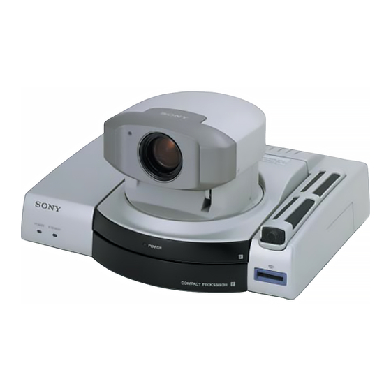
System Configuration The PCS-1600/1600P Compact Conference Package is a basic system that can be enhanced with variety of optional equipment. Basic System Equipment The PCS-1600/1600P Compact Conference Package forms the basis of the PCS-1600 series system. The PCS-1600/1600P Compact Conference Package consists... -
Page 14: Options
A TV is used as a meeting monitor and TV monitor speaker. It displays the remote party, graphics, and menus. If you use a Sony TV, you can operate it with the Remote Commander supplied with the Compact Conference Package. Two monitors are required for a dual- monitor system. - Page 15 Unit Description PCS-I160 Provides two ISDN jacks. The connection with 6B channels is available. BRI Board Provides the V.35 connector. The PCS-I161 V.35 Board connection via the V.35 interface is available. Connects one end to the V.35 connector PCS-K32 V.35 Conversion (on the PCS-I161 V.35 Board) and the other end to the terminal adaptor.
-
Page 16: Basic System Connection
Basic System Connection Connect the TV monitor and the AC adaptor to the Compact Processor, and connect to the ISDN line with the supplied ISDN modular cable. The following cables; the ISDN modular cable and the audio cord, each cable is equipped with the color label. When connecting these cables, match the label color with the color of the connector name printed on the rear panel. -
Page 17: Preparing The System
Preparing the System Inserting Batteries into the Remote Commander The supplied Remote Commander controls most of the functions. This section describes how to insert batteries into the Remote Commander. Remove the battery compartment cover. Insert two size AA (LR6) alkaline batteries (supplied) with correct 3 and # polarity into the battery compartment. -
Page 18: Preparing The Tv Monitor
I/1 button on the Remote Commander. If the IR repeater does not function properly, set Monitor Mode in the General Setup menu to MODE2 (PCS-1600); to MODE4 (PCS-1600P). For details on the Monitor Mode setting, see “General Setup menu”... -
Page 19: Setting The Initial Volume Level On The Tv
The TV monitor can be operated from the Remote Commander. For details on operating the Remote Commander, see “To operate a Sony TV monitor” on page 136. To adjust the TV monitor screen Use the controls on the TV monitor to adjust the screen (picture, hue, contrast, brightness, and sharpness). -
Page 20: Installing The Compact Processor
Preparing the System Installing the Compact Processor When you install the Compact Processor, use the supplied Velcro. This will prevent the Compact Processor from sliding off. Stick one side of the supplied Velcro to the bottom of the Compact Processor. Stick the other side of the Velcro to the top of the TV monitor. -
Page 21: Turning The System On/Off
Turning the System On/Off This section describes how to turn on and off the Compact Processor. Note Set the CONF/DOC/TV selector on the Remote Commander to “CONF” when operating the Compact Processor. Turning On The following describes how to turn on the Compact Processor. Make sure the TV monitor is on standby. -
Page 22: When The Compact Processor Is Turned On For The First Time
Notes • The POWER lamp on the camera does not flash even if the system is in sleep mode. • A Sony TV monitor is turned into standby mode. When the Compact Processor is turned on for the first time The setup wizard appears on the monitor screen after the self- diagnostic is completed. - Page 23 Set up the following items. Country/Region: Selects your country or region. Country/Region Code: Enters your country code or region code in the box. (e.g., enter “1” for the USA.) Protocol: Selects the nework switch type. (This is only for the USA and Canada.) Country/Region: Country/Region Code: Protocol:...
- Page 24 Turning the System On/Off When you select Auto SPID You can automaically set up the Area Code, Local Number on this page, and SPID items on the next page. Notes • “Auto SPID” is only for the USA and Canada. •...
- Page 25 Set up the following items. DHCP Mode: Sets up the DHCP (Dynamic Host Configuration Protocol). Auto: Automatically gets your IP address and network mask. Check your IP address on the Machine Information menu after you get them. Off: Sets DHCP to OFF. When set to OFF, enter your IP address and network mask.
-
Page 26: Setting The System (Compact Conference Package) To Be On Standby
Turning the System On/Off Setting the System (Compact Conference Package) to be on Standby When the system is on standby, you can turn the system on with the I/1 button on the Remote Commander. Press the I/1 button on the Remote Commander. The indication “Power off?”... -
Page 27: On The Help Menu
Information menu” on page 104. Machine Information Host Version: Ver1.51 BRI Version: Ver3.31 VCP Version: Ver1.00 DSP Version: Ver1.00 Software Option: None Option Board: None Host Name: PCS-1600 IP Address: 1.2.3.4 MAC Address: 00-00-00-00-00-00 Serial Number: 12345 Machine Information menu Chapter 1 Preparation... -
Page 28: Turning Off
Turning the System On/Off Turning Off The following describes how to turn off the Compact Processor. Set the POWER switch on the rear of the Compact Processor to off. Turn off the power of any other equipment which was used during the meeting. -
Page 29: How To Operate The Menu
How to Operate the Menu The different menu is opened whether the system is in communication or not. Switching the Menu Not in Communication The following launcher menu is always displayed when the system is not in communication. Select the desired menu with the joystick on the Remote Commander, then press the joystick. -
Page 30: Switching The Menu In Communication
How to Operate the Menu Camera Angle menu This is used to control the angle and zoom of the camera. (Pressing the CAMERA button on the Remote Commander accesses the Camera Angle menu directly.) For details on the Camera Angle menu, see page 50. Setup menu This is used to register or modify the setup of the system. - Page 31 Still Image menu This is used to control a still image. (Pressing the STILL IMAGE button on the Remote Commander accesses the Still Image menu directly.) For details on the Still Image menu, see pages 61 to 64. Camera menu This is used to control the camera.
-
Page 32: Operating The Menu
How to Operate the Menu Operating the Menu This describes the basic menu operation, taking the Dial Setup menu as an example. Open the Dial Setup menu from the Setup menu (page 29). Dial Setup Page: 1/4 Line I/F: ISDN Bonding: Auto Number of Lines:... -
Page 33: Turning Off The Indicators
To page up or down the menu Select Page with the joystick on the Remote Commander, then move the joystick to the right or left. To return to the previous level hierarchy of the menu Press the RETURN button on the Remote Commander. Turning Off the Indicators Press the DISPLAY button on the Remote Commander to turn off the indicators. - Page 34 How to Operate the Menu To enter characters Press the number buttons on the Remote Commander to enter the desired character. Each time you press the button, the character is input from among the alphabets on each button, or the numbers on each. To enter special characters (symbols), press the PHONE BOOK (SYMBOL) button repeatedly to select a desired character.
-
Page 35: Basic Operation During A Meeting
Chapter Basic Operation During a Meeting Calling a Remote Party You can start a meeting with a remote party by dialing. Once you have made a connection with the remote party, you can begin talking just like normal phone call. The following describes how to call a remote party. -
Page 36: Calling An Unregistered Remote Party
Calling a Remote Party Calling an Unregistered Remote Party The following launcher menu is always displayed on the monitor screen not in communication. Phone Book Manual Dial Camera Angle Setup Select Manual Dial with the joystick on the Remote Commander, then press the joystick. Or press the CONNECT/DISCONNECT ( / ) button on the Remote Commander. - Page 37 When connecting via the ISDN lines Enter the telephone number of the remote party to have a meeting with in the A1 and A2 boxes. • To copy a telephone number, press the CAMERA (LINE COPY) button. The number entered are copied to the next box.
- Page 38 Calling a Remote Party Select the prefix setting. Select Prefix with the joystick on the Remote Commander, then press the joystick. Select the desired setting with the joystick moved up or down, then press the joystick. None: Does not use the prefix number. Prefix-A: Uses the setting A set in the Dial Setup menu.
-
Page 39: Calling A Registered Remote Party
To cancel dialing before the connection is completed Select Cancel with the joystick on the Remote Commander, then press the joystick. Or press the CONNECT/ DISCONNECT ( / ) button on the Remote Commander. To set up other items than the items above When More Options Enable is set to On in the Dial Setup menu, the More Options button is displayed at the lower part of the menu. - Page 40 Calling a Remote Party Select the remote party with the joystick on the Remote Commander, then press the joystick. The sub-menu is opened on the monitor screen. Phone Book Recent Dial Edit Copy Delete New Entry You can sort the list on the Phone Book menu. For details, see “To sort the list on the Phone Book menu”...
- Page 41 To sort the list on the Phone Book menu You can sort the list on the Phone Book menu. The list on the Phone Book menu will be sorted by selecting the buttons at the right on the menu. When you select Recent, most recently dialed six indexes are displayed.
-
Page 42: Receiving A Call
Receiving a Call When a call comes in, the connection process with differs depending on the setting of the answer mode. Auto answer mode The system automatically receives the call and starts the meeting. However, even if you are not ready to start the meeting, the local picture will be displayed on the remote party’s monitor screen. -
Page 43: Answering Calls In Manual Answer Mode
Answering Calls in Manual Answer Mode When your system is in manual answer mode, you need to connect incoming calls manually. When a call comes in, the Compact Processor starts ringing, and the indication “Incoming Call. Respond?” appears on the monitor screen. - Page 44 Receiving a Call When the optional PCS-UC161 Upgrade Kit has been installed If a call comes in via the ISDN line during the meeting on a LAN, the Compact Processor is busy. Chapter 2 Basic Operation During a Meeting...
-
Page 45: Checking The Connection Status
Checking the Connection Status During a meeting, you can check the status of the communication. Elapsed time also appears on the monitor screen during a meeting. Open the Communication Status menu. Communication Status Page: 1/2 Far End Line I/F Camera Control Line Rate 2 x 64K T.120 Data... - Page 46 Checking the Connection Status To close the Communication Status menu Select End with the joystick on the Remote Commander, then press the joystick. The menu returns to the Setup menu. On elapsed time When you set Time Display to On in the General Setup menu, the elapsed time appears on the monitor screen during a meeting.
-
Page 47: Adjusting The Sound
Adjusting the Sound Adjusting the Volume You can adjust the volume sent from remote parties. Press the VOLUME/DOC-BRIGHT + button to increase the volume; the VOLUME/DOC-BRIGHT – button to decrease it. The volume bar appears on the monitor screen. After awhile, the bar automatically disappears if you do not operate. -
Page 48: On The Echo Canceler
Adjusting the Sound When you use the lip synchronization, set Lip Sync to On in the Audio Setup menu. When you do not use the lip synchronization, set it to Off. For details on the Lip Sync setting, see “Audio Setup menu” on page 97. -
Page 49: Adjusting The Camera
Adjusting the Camera You can adjust the local camera to obtain the best viewing results. During communication, you can also adjust the remote camera, and adjust images being sent from the remote camera. Notes • A malfunction may occur if the local and remote parties try to adjust the same camera at the same time. -
Page 50: Adjusting The Camera Angle And Zoom
Adjusting the Camera Note You cannot control the remote camera if you do not set Far End Camera Control to On in the Dial Setup menu at the local, and set Far End Camera Control to Off in the Answer Setup menu at the remote. -
Page 51: Adjusting Focus And Brightness
Adjusting Focus and Brightness Focus and brightness are automatically adjusted. We recommend you not to use the manual adjustments since the camera automatically adjust itself for the best focus and brightness. Select Adjustment with the joystick on the Remote Commander in the Camera menu, then press the joystick. The guidance will appear and you can adjust the focus and brightness. -
Page 52: Presetting Angle And Zoom Settings
Adjusting the Camera Presetting Angle and Zoom Settings You can store the camera settings in memory up to six, and each preset has the angle and zoom settings. Once a setting has been stored, you can easily recall a setting from the six presets. - Page 53 To recall a preset Select Preset Load with the joystick on the Remote Commander, then press the joystick. Select the number button (1 to 6) with the joystick on the Remote Commander, then press the joystick. The camera is automatically adjusted by the preset under the selected number.
-
Page 54: Tracking A Subject Automatically - Automatic Target Tracking Function
Adjusting the Camera Tracking a Subject Automatically — Automatic Target Tracking Function You can have the camera memorize a particular color or brightness so that automatically tracks a subject having the memorized color or brightness. If a subject almost goes off the screen, the camera performs the pan/tilt action so that the subject is placed back in the middle of the screen. - Page 55 Press the joystick on the Remote Commander. The indication appears on the monitor screen. The automatic target tracking function starts and the frame disappears from the monitor screen. To cancel the automatic target tracking function Select Auto Track Cancel with the joystick on the Remote Commander, then press the joystick.
-
Page 56: Selecting The Picture And Sound
Selecting the Picture and Sound You can select the picture and sound from both the local and remote sites equipment. To switch the picture To switch the picture displayed on the monitor from the local or remote picture Press the FAR/NEAR button on the Remote Commander, then switch the picture by selecting the icons on the monitor screen with the joystick on the Remote Commander. -
Page 57: Monitoring Yourself In The Inset Window
Monitoring Yourself in the Inset Window The inset window allows you to monitor your own party while viewing the remote party. (Picture-in-picture function) Press the PinP button on the Remote Commander in communication. If an inset window is not displayed, the inset window appears on the monitor screen. -
Page 58: Displaying A Still Picture
Displaying a Still Picture You can use still pictures stored in a “Memory Stick.” Displaying a Still Picture Stored in the “Memory Stick” Insert the “Memory Stick” into the Memory Stick slot. Insert it in the arrow mark direction with the mark faced upward. -
Page 59: Notes On A "Memory Stick
General Setup menu, then select OK. The “Memory Stick” will be formatted. However, the still pictures and Phone Book list stored in the “Memory Stick” will be also deleted. “Memory Stick” and are trademarks of Sony Corporation. Chapter 2 Basic Operation During a Meeting... -
Page 60: Clearing The Still Picture From The Screen
Displaying a Still Picture Clearing the Still Picture From the Screen Press the joystick on the Remote Commander. Chapter 2 Basic Operation During a Meeting... -
Page 61: Sending Still Pictures
Sending Still Pictures When you send pictures that contain lots of text, we recommend you to send that picture as a still picture. Since still pictures are more clear than moving pictures for reading text. You can send a video as a still picture of external equipment connected to the the Compact Processor, or of the camera. -
Page 62: Sending Still Pictures Continuously
Sending Still Pictures Sending Still Pictures Continuously Open the Still Image menu. Set up the angle and zoom if you readjust them. For details on the angle and zoom settings, see “Adjusting the Camera Angle and Zoom” on page 50. Select Continuous Send with the joystick on the Remote Commander, then press the joystick. -
Page 63: Clearing The Still Picture From The Screen
Note Create the directory “¥DCIM¥100MSDCF” for the “Memory Stick,” and store the file under that directory. The file format must be as follows: “NNNnnnnn.JPG” (N = alphabet, n = number). Clearing the Still Picture From the Screen Open the Still Image menu, and select Stop with the joystick on the Remote Commander, then press the joystick. -
Page 64: Saving A Still Picture Into The "Memory Stick
Saving a Still Picture Into the “Memory Stick” Display the still picture to be stored. Insert the “Memory Stick” into the Memory Stick slot. Open the Still Image menu. Select Save with the joystick on the Remote Commander, then press the joystick. The selected still picture is stored into the “Memory Stick.”... -
Page 65: Sending The Dial Tone To The Remote Party
Sending the Dial Tone to the Remote Party You can send the dial tone (Dual Tone Multi Frequency) assigned to the 0 – 9, , and buttons on the Remote Commander to control the remote system. Press the button on the Remote Commander. The DTMF screen appears on the monitor screen. -
Page 66: Ending A Meeting
Ending a Meeting Press the CONNECT/DISCONNECT ( / ) button on the Remote Commander. The message appears on the monitor screen. To disconnect the call Select OK with the joystick on the Remote Commander, then press the joystick. Or press the CONNECT/DISCONNECT ( / ) button on the Remote Commander again. -
Page 67: Advanced Operation
Chapter Advanced Operation Connecting With an MCU You can perform a multiple communication with making a connection to an MCU (Multipoint Control Unit). Once you connect with the MCU that has the chair control function, the chair control is activated among 99 terminals. Note When you have upgraded the system using the optional PCS- UC161 Upgrade Kit and using a LAN, the chair control is... - Page 68 Connecting With an MCU Select Chair Request from Broadcast Mode with the joystick on the Remote Commander. Note When you do an incapable operation, the indication “Command is rejected by MCU” appears on the monitor screen. To see a picture of the selected terminal Select Receive from Broadcast Mode with the joystick on the Remote Commander.
- Page 69 To broadcast a picture of the selected terminal to all the terminals Select Broadcast from Broadcast Mode with the joystick on the Remote Commander. Select the terminal number with the joystick moved up or down, then press the joystick. A picture of the selected terminal appears on your monitor and it is broadcast to all terminals.
-
Page 70: Voice Meeting
Voice Meeting The system can connect to a normal phone to hold a meeting using the sound only. (Voice Meeting) The basic procedure is same as one with images and sound. Note When you have upgraded the system using the optional PCS- UC161 Upgrade Kit and using a LAN, you cannot do the voice meeting. -
Page 71: Registration And Setup
Chapter Registration and Setup Registering a Remote Party You can register a remote party before making the connection. You can register up to 500 remote parties. Notes • Register the information in the boxes B1 to C2 when you have installed the optional PCS-I160 BRI Board to use three ISDN lines. -
Page 72: Making An Entry
Registering a Remote Party Making an Entry Press the PHONE BOOK button on the Remote Commander. The Phone Book menu appears on the monitor screen. Phone Book Recent New Entry Select New Entry with the joystick on the Remote Commander, then press the joystick. The List Edit menu appears on the monitor screen. - Page 73 Set up the line interface. ISDN: Connects to a TV conferencing system via the normal ISDN line. Telephone: Connects to a phone to have a voice meeting via the normal ISDN line. V.35: Connects to a TV conferencing system via the V.35 interface.
- Page 74 Registering a Remote Party Select the line interface icons or still images stored in the “Memory Stick.” Move the joystick to the left or right to select the icon or still image, then press the joystick. Note If the “Memory Stick” which has still images is not inserted, you cannot select still images.
-
Page 75: Modifying An Entry
To set up other items than the items above When More Options Enable is set to On in the Dial Setup menu, the More Options button is displayed at the lower part of the menu. Select More Options with the joystick on the Remote Commander, then press the joystick. -
Page 76: Deleting Registered Entries
Registering a Remote Party Deleting Registered Entries You can delete a registered entry as follows. Select the Index title to be deleted with the joystick on the Remote Commander. Select Delete with the joystick on the Remote Commander, then press the joystick. The indication “Delete list?”... -
Page 77: Notes On Registration
Notes on Registration General note If the Restrict setting of the remote party is set to 56K in the Answer Setup menu, the connection will be made at 56 Kbps even if you set Restrict to Auto in the Dial Setup menu. Note on the optional PCS-I160 BRI Board If you have installed the optional PCS-I160 BRI Board, you can use three ISDN lines (up to 6B channels). -
Page 78: Registering Local Information
Registering Local Information Before holding a meeting, you will need to register your local information on the ISDN Setup menu, such as the local directory number. Setting Up the ISDN Setup Menu Select Setup with the joystick on the Remote Commander in the launcher menu, then press the joystick. - Page 79 Enter your country code or region code in the Country/ Region Code box. (e.g., enter “1” for the USA.) Select Page 1/3 with the joystick on the Remote Commander, then move the joystick to the right. The ISDN Setup menu (Page 2) appears on the monitor screen.
-
Page 80: Registering Local Information
Registering Local Information Set up the ISDN Setup (SPID) menu. (This is only for the USA and Canada.) For details on the SPID registration, see “SPID Registration for Customers in the USA” on page 81. Select Save with the joystick on the Remote Commander, then press the joystick. -
Page 81: Spid Registration For Customers In The Usa
SPID Registration for Customers in the USA If the system is connected to a network switch of the following types, you can use ISDN lines. • Network switch type: AT&T 5ESS Network switch software version: 5E8 or later (for National ISDN-1 and National ISDN-2) •... - Page 82 SPID Registration for Customers in the USA Enter your country code in the Country Code box. If the network switch type is AT&T 5ESS (National ISDN) or NTI DMS-100 (National ISDN) Country Code is “1” If the network switch type is AT&T 5ESS (Multipoint Custom ISDN) Country Code is “1 10”...
- Page 83 ISDN Setup Page: 2/3 Area Code Local Number 9876532 9876532 9871356 9871356 9852464 9852464 Auto SPID Save Cancel In case of each LDN is different as a separate LDN is given for each channel. ISDN Setup Page: 2/3 Area Code Local Number 9876543 9876544...
- Page 84 SPID Registration for Customers in the USA The following shows the use of three ISDN lines for AT&T 5ESS (Point-to-Point Custom ISDN). ISDN Setup Page: 2/3 Area Code Local Number 9876532 9876532 9871356 9871356 9852464 9852464 Auto SPID Save Cancel If the network switch type is NTI DMS-100 (National ISDN or Custom ISDN) Each LDN is different as a separate LDN is given for each...
- Page 85 Open the ISDN Setup (SPID) menu (Page 3). SPID in the ISDN Setup (SPID) menu and the Local Number in the ISDN Setup menu (Page 2) are entered in pairs and should not be crossed with BRI channels as each has its own LDN.
- Page 86 SPID Registration for Customers in the USA If the network switch type is AT&T 5ESS (Multipoint Custom ISDN) The following shows the use of three ISDN lines. ISDN Setup Page: 1/3 Country Name: Country Code: 1 10 Protocol: AT&T P-MP Save Cancel ISDN Setup...
- Page 87 ISDN Setup ISDN Setup Page: 2/3 Page: 3/3 Area Code Local Number SPID 9876532 9876532 9871356 9871356 9852464 9852464 Auto SPID Save Cancel Auto SPID Save Cancel If the network switch type is NTI DMS-100 (National ISDN) The following shows the use of three ISDN lines. ISDN Setup ISDN Setup Page: 2/3...
- Page 88 SPID Registration for Customers in the USA ISDN Setup ISDN Setup Page: 2/3 Page: 3/3 Area Code Local Number SPID 9876543 019876543001 9876544 019876544001 9871234 019871234001 9871235 019871235001 9852468 019852468001 9852469 019852469001 Auto SPID Save Cancel Auto SPID Save Cancel You should let the remote party user know the contents of your LDN.
-
Page 89: Menu Items In The Setup Menu
Menu Items in the Setup Menu Dial Setup Menu Sets up the attribute for calling. Page 1 Dial Setup Page: 1/4 Line I/F: ISDN Bonding: Auto Number of Lines: Restrict: Auto LAN Bandwidth: 1024 Prefix: None Save Cancel Line I/F: Selects the line interface. ISDN: Connects to a TV conferencing system via the normal ISDN line. - Page 90 Menu Items in the Setup Menu Restrict: Selects the transfer rate via the ISDN line. Auto: Normally, select this setting. 56K: Selects this setting when you call a region or country via the 56 Kbps transfer rate. LAN Bandwidth: Sets up the bandwidth of a LAN. This item can be set between 1 and 1024K.
- Page 91 Audio Mode: Selects the protocol for the audio encoding. G.728: The audio bandwidth is narrow but the image quality is better. (G.728: 3.4 kHz) G.722: The audio bandwidth is wider for better sound quality. (7 kHz) G.711: Select this setting when the remote system does not support neither G.722 nor G.723.
- Page 92 Menu Items in the Setup Menu Page 3 Enter “9” when you have to dial nine to reach an outside line. Dial Setup Page: 3/4 Prefix A: Prefix B: Prefix C: Save Cancel Prefix A: Sets up a prefix number that will be registered for Prefix-A in the Dial Setup menu.
- Page 93 Page 4 Dial Setup Page: 4/4 Telephone: Auto More Options Enable: V.35 RS-366: Save Cancel Telephone: Selects the audio protocol for the voice meeting. Auto: Selects the protocol automatically. G.711 µ-law: Selects the µ-law protocol. G.711 A-law: Selects the Α-law protocol. More Options Enable: Selects whether to enable the dial attribute set in the Dial Setup menu for each dial list.
-
Page 94: Answer Setup Menu
Menu Items in the Setup Menu Answer Setup Menu Sets up the communication items for receiving. Page 1 Answer Setup Page: 1/2 Auto Answer: Number of Lines: Restrict: Auto LAN Bandwidth: 1024 ISDN Dial In: Save Cancel Auto Answer: Selects the answer mode. On: Answers calls in auto answer mode. - Page 95 Page 2 Answer Setup Page: 2/2 Video Mode: H.261 Video Frame: 30fps Audio Mode: G.728 Audio Mode Threshold: Up to 64K:G.728 Far End Camera Control: T.120 Data: Save Cancel Video Mode: Selects the protocol for the video encoding. H.261: Receives pictures based on Recommendation H.261. H.263: Receives pictures based on Recommendation H.263.
-
Page 96: Mcu Setup Menu
Menu Items in the Setup Menu MCU Setup Menu When you have upgraded the system using the optional PCS- UC160 Upgrade Kit and hold an MCU conference, set up the MCU Setup menu. Note The MCU Setup menu is displayed only when the system has been upgraded using the optional PCS-UC160 Upgrade Kit. -
Page 97: Audio Setup Menu
Audio Mode: Selects the protocol for the audio encoding. G.728: The audio bandwidth is narrow but the image quality is better. (3.4 kHz) G.722: The audio bandwidth is wider for better sound quality. (7 kHz) G.711: When not using G.722 and G.728. Audio Setup Menu Sets up the audio system. -
Page 98: General Setup Menu
Menu Items in the Setup Menu Beep Sound: Selects whether to sound the beep when you press the buttons on the Remote Commander. On: Activates the beep sound. Off: Deactivates the beep sound. Recording Mute: Selects whether to output the audio from the AUDIO OUT (MIXED) jack. - Page 99 Spanish: Displays messages in Spanish. Italian: Displays messages in Italian. Monitor Mode: Selects the remote control mode of the IR repeater. Normally, set it to MODE1 (PCS-1600) or to MODE3 (PCS-1600P). MODE1: Sets it to mode 1. MODE2: Sets it to mode 2.
-
Page 100: Administrator Setup Menu
Menu Items in the Setup Menu Page 3 General Setup Page: 3/3 T.120 PC Address: Save Cancel T.120 PC Address: Input the IP address of the PC used for the T.120 data conference. Administrator Setup Menu This menu is only for an administrator. If you set your password, the password is necessary to modify the Setup and Phone Book menus. -
Page 101: Isdn Setup Menu
Web Monitor: Selects whether or not the Web monitoring function is used from the Web. On: Gives permission for viewing the JPEG images from the Web. Off: Does not give permission for viewing the JPEG images from the Web. ISDN Setup Menu Sets up the ISDN attribute. - Page 102 Menu Items in the Setup Menu Host Name: Enter your host name. IP Address: Enter your IP address. Network Mask: Enter your network mask. Gateway Address: Enter your default gateway address. DNS Address: Enter your DNS (Domain Name System) server address. Page 2 LAN Seup Page: 2/3...
- Page 103 Page 3 LAN Setup Page: 3/3 SNMP Mode: Trap Destination: Community: Description: Location: Contact: Save Cancel SNMP Mode: Sets up whether the SNMP agent service is effective or not. On: Sets the SNMP agent service effective. Off: Sets the SNMP agent service ineffective. Trap Destination: Enter your SNMP administrator address where you send the trap.
-
Page 104: Machine Information Menu
VCP Version: Ver1.00 DSP Version: Ver1.00 Software Option: None Option Board: None Host Name: PCS-1600 IP Address: 1.2.3.4 MAC Address: 00-00-00-00-00-00 Serial Number: 12345 Host Version: Displays the software version. BRI Version: Displays the BRI version. VCP Version: Displays the VCP version. -
Page 105: Meetings With Optional Equipment
Installing the Optional Board You need to install the optional board to connect via three ISDN lines or via the V.35 interface. For details on the installation of optional Boards, consult your Sony dealer. Board Function PCS-I160 BRI Board Connects via three ISDN lines. -
Page 106: Using Three Isdn Lines
Installing the Optional Board Using Three ISDN Lines You need to install the optional PCS-I160 BRI Board. You can connect with 6B channels. ISDN modular cables (supplied with the PCS-I160) to ISDN B to ISDN C AUDIO VIDEO ISDN B ISDN C AUX2 AUX1... -
Page 107: Upgrading The Software
Upgrading the Software Follow the procedure below to upgrade the software. To install the Upgrade Kit Insert the “Memory Stick” into the Memory Stick slot. Insert it in the arrow mark direction with the mark faced upward. Turn on the Compact Processor. After the upgrade is complete, the launcher menu appears. -
Page 108: Connection Using A Lan
100 BASE-TX/ 10 BASE-T Note Set the mode setting (communication speed and half-/full- dulex) of the hub to the automatic or half-duplex mode. The setting of the PCS-1600/1600P is set to the automatic mode. Chapter 5 Meetings With Optional Equipment... -
Page 109: Using Dual Monitors
Using Dual Monitors You can use two monitors during a meeting, one for moving pictures and the other for still pictures. To connect a TV monitor for the dual monitor function Connect the second TV monitor (for dual monitor function) to the VIDEO MONITOR OUT2 jack on the Compact Processor. -
Page 110: Using Optional Microphones
Using Optional Microphones The Compact Conference Package is designed to accommodate three participants at one terminal. You can add the optional PCS-A300 Microphones to allow for more participants. Notes • Set Mic Select to External in the Audio Setup menu. •... -
Page 111: Recording The Meeting Audio
Recording the Meeting Audio You can record the audio during a meeting. Connect a cassette recorder to the AUDIO OUT (MIXED) jack. You can record both local and remote audios, or only record remote audios. When you record both local and remote audios, set Recording Mute to On in the Audio Setup menu. -
Page 112: Using The External Equipment
Using the External Equipment The Compact Processor can connect two external video equipment for input; two equipment for output (including the TV monitor). Connecting External Video Equipment for Input Connect video equipment, such as a VCR. The system is equipped with two video inputs and one audio input. AUDIO VIDEO (PLUG IN POWER) -
Page 113: Connecting External Equipment For Output
Connecting External Equipment for Output You can connect external video equipment for output, such as a VCR, besides the TV monitor. AUDIO VIDEO (PLUG IN POWER) AUX2 AUX1 DC12V 100BASE-TX/ AUDIO OUT POWER 10BASE-T (MIXED) ISDN A IR OUT1 IR OUT2 AUX OUT MONITOR OUT to VIDEO AUX... -
Page 114: Holding A T.120 Data Conference
Holding a T.120 Data Conference You can have a data conference based on ITU-T Recommendation, T.120 standards when you connect a PC which NetMeeting (not supplied) has been installed with the Compact Processor. NetMeeting is a registered trademark of Microsoft Corporation. -
Page 115: Setting Up The Compact Processor
When you use a Hub, connect as follows using straight cables. AUDIO VIDEO (PLUG IN POWER) AUX2 AUX1 DC12V 100BASE-TX/ AUDIO OUT POWER 10BASE-T (MIXED) ISDN A IR OUT1 IR OUT2 AUX OUT MONITOR OUT to LAN to 100BASE-TX/ 10BASE-T To install NetMeeting Install NetMeeting in your PC following the procedure. -
Page 116: Connecting With Netmeeting
Holding a T.120 Data Conference Connecting with NetMeeting Select [NetMeeting] from the start pop-up menu or click on the NetMeeting icon. Set the Compact Processor to be on line. Check that the indication [T.120] appears on the screen. Click on [Calling] at both local or remote. Enter the IP address of the Compact Processor into [Address]. -
Page 117: Meetings With The Upgrade Kit
Chapter Meetings With the Upgrade Kit Features The optional PCS-UC160 Upgrade Kit is designed to add the MCU function to the PCS-1600/1600P Compact Conference Package. You can hold an MCU conference based on the ITU-T Recommendation, H.231 standard. Note The PCS-I160 BRI Board is also required for holding a point to multi-point meeting. -
Page 118: Starting A Point To Multi-Point Meeting
Starting a Point to Multi-Point Meeting You can hold a point to multi-point meeting among four terminals (including this terminal). You can add one normal audio phone in the network. Note Before you start a meeting verify that MCU Mode is set to On in the MCU Setup menu. -
Page 119: Receiving Calls
To call unregistered remote parties Select Manual Dial with the joystick on the Remote Commander in the launcher menu, then press the joystick. The Manual Dial menu appears on the monitor screen. Enter the telephone number of the first remote party to have a meeting with in the A1 and A2 boxes (when Number of Lines is set to 1B, only in the A1 box). -
Page 120: Notes On Point To Multi-Point Meetings
Starting a Point to Multi-Point Meeting Notes on Point to Multi-Point Meetings See also “The Attribute” on page 127. • The chair control is only available from this terminal. Remote parties cannot operate it. • This system does not support multiplex MCU connections. •... -
Page 121: Operating Chair Controls
Operating Chair Controls You can do the following operations during a meeting. Switching the Broadcast Mode There are two broadcast modes: 4 Split mode Displays each party on the four-split screen. The picture via the The picture via the ISDN A jack ISDN B jack The picture of this The picture via the... -
Page 122: Selecting The Picture To Be Broadcast
Operating Chair Controls Select 4 Split or Voice Active from Broadcast Mode with the joystick on the Remote Commander, then press the joystick. Each time you select the setting, the mode is switched between the 4 Split mode and the Voice Active mode. Selecting the Picture to be Broadcast You can manually select the picture to be broadcast. -
Page 123: Verifying The Picture Shot By The Local Camera
Verifying the Picture Shot by the Local Camera You can display the local picture only on your screen in Voice mode; the other terminals are still in Voice mode. Press the FAR/NEAR button on the Remote Commander. The local picture is displayed only on your screen. To return to the Voice mode Press the FAR/NEAR button on the Remote Commander again. -
Page 124: Ending A Point To Multi-Point Meeting
Ending a Point to Multi-Point Meeting Press the CONNECT/DISCONNECT ( / ) button on the Remote Commander. The following menu appears on the monitor screen. Disconnect Phone Book Manual Dial Cancel Select Disconnect with the joystick on the Remote Commander, then press the joystick. The screen changes to the four-split screen, and the following menu appears on the monitor screen. -
Page 125: Notes On Secondary Terminals
Notes on Secondary Terminals If the terminal that is not adequate for the setting on this system is connected, this terminal is called as the secondary terminal. When the secondary terminal is connected, some of the function is limited as follows: When a normal phone is connected You can connect only one normal audio phone in the network. -
Page 126: Notes On Secondary Terminals
Notes on Secondary Terminals When the terminal whose video rate is lower is connected Broadcasts the picture to all the terminals with the lowest frame rate in the network. When the terminal whose video mode is only QCIF is connected Does not broadcast the picture to the QCIF terminal. -
Page 127: The Attribute
The Attribute Number Attribute Value Maximum number of terminals that 3 (4 when including this terminal) can be connected to a single MCU Maximum number of concurrent (independent) conferences that can be supported in a single MCU Maximum number of ports that can be connected to other MCUs Network interfaces at each port Restricted network capability... - Page 128 The Attribute Number Attribute Value 13.3 H.224 (simplex data) Cascading 14.1 Fixed rates (“simple”) 14.2 Master/Slave Terminal identification MBE capability Register necessary information such as the telephone number and index number. Chapter 6 Meetings With the Upgrade Kit...
-
Page 129: Appendix
Appendix Location and Function of Parts and Controls Compact Processor Main unit (front) (Continued) Appendix... - Page 130 Location and Function of Parts and Controls 1 POWER lamp (green) When you set the POWER switch to on, this lamp lights up. This lamp goes off when the system is on standby, or flashes when the system is in sleep mode.
- Page 131 Main unit (rear) AUDIO VIDEO (PLUG IN POWER) AUX2 AUX1 DC12V 100BASE-TX/ AUDIO OUT POWER 10BASE-T (MIXED) ISDN A IR OUT1 IR OUT2 AUX OUT MONITOR OUT 2 3 4 5 6 7 8 9 0 qa 5 AUDIO OUT (MIXED) jack 1 U Terminal (phono jack) Connect the earthing wire to this...
- Page 132 Location and Function of Parts and Controls 9 VIDEO AUX OUT jack (phono qj Camera screws jack) Loosen these screws to detach the Connect to the video input jack of the camera from the main unit. external equipment. Note 0 VIDEO MONITOR OUT1 jack Tighten the camera screws firmly.
- Page 133 Camera Front Rear 1 Lens 6 BACKUP switch Set it to ON to store the presets. 2 POWER lamp (green) When you set the POWER switch to on, this lamp lights up. This lamp goes off when the system is on standby. 3 Remote sensor When operating the Compact Processor, point it toward this sensor.
- Page 134 Location and Function of Parts and Controls Remote Commander CONF CONNECT/ DISCONNECT PQRS WXYZ 10/0 VIDEO INPUT DISPLAY HELP SELECT PUSH ENTER VOLUME/ ZOOM/ DOC-BRIGHT TV-CH MIC/ DOC-DARK ON/OFF Appendix...
- Page 135 Processor. an item, or to control the camera. DOC: Operates the optional PCS- DS150/DS150P Document Stand. qa VOLUME/DOC-BRIGHT (+/–) TV: Operates a Sony TV. buttons 2 CONNECT/DISCONNECT ( / These buttons adjust the volume. +: press to increase the volume.
- Page 136 T+: press to zoom in the picture. Note W–: press to zoom out the picture. When you operate a Sony TV, set the CONF/DOC/TV selector to “TV.” qg MENU button Displays the menu on the monitor qa VOLUME/DOC-BRIGHT (+/–) screen.
-
Page 137: On Screen Messages
On Screen Messages The following messages appear on the TV monitor when using the Compact Processor and gives instructions on dealing with them. Message Remedy INCORRECT DIALING SETUP Make sure the selected entry is correctly registered. CANNOT COMPLETE CONNECTION — (The following code and message appear.) Unknown network error:... - Page 138 On Screen Messages Message Remedy Try again later. LAN connection timeout: LAN connection rejected: Try again later. DNS error: Please check DNS. Please check the address and try again. Dialing your own number is invalid: GateKeeper error: Please check the address and try again. FAR END INACTIVE The remote party operates the menu.
- Page 139 The following messages indicate the state of the system. No action is required. Message Meaning MEETING STARTS! Connection with the remote party has been completed, the meeting can now begin. MEETING ENDS Operations for ending the meeting have been completed. Charges are ****.
-
Page 140: Troubleshooting
Troubleshooting If the Compact Processor does not function or functions incorrectly, check the following. Symptom Cause Solution The power is not The POWER switch is not set Set the POWER switch to on. See turned on. to on. page 21. The batteries in the Remote Replace the batteries with new Commander are low or dead. - Page 141 Symptom Cause Solution Does not connect with Turn on the terminal adaptor. The terminal adaptor is not a remote party. turned on (if you have installed an optional interface board). Register the remote party. See The remote party has not page 71.
-
Page 142: Specifications
(or up to 3 lines when QCIF: 176 pixels × installing the PCS-I160) 144 lines V.35 (RS-366) (when Color system installing the PCS- NTSC (PCS-1600) I161): 56 Kbps, PAL (PCS-1600P) 64 Kbps, 56 Kbps to 384 Kbps LAN (when upgrading Still Picture with the PCS-UC161 704 pixels ×... -
Page 143: Remote Control
(5 m, 16.4 ft) (1) Illumination range AC adaptor (1) 7 lux to 100 000 lux Power cord (1) Horizontal resolution 21-pin adaptor (1) (PCS- 460 TV lines (PCS-1600) 1600P only) 450 TV lines (PCS- Velcro (2) 1600P) Operating instructions (1) Appendix... -
Page 144: Specifications
Specifications Optional microphone PCS- Remote Commander A300 (PCS-R160) Bandwidth 7.0 kHz Dimensions 68 × 15 × 90 mm (w/h/d) Signal format × × Infrared SIRCS inches) Control DC 3V using two size Mass Approx. 200 g (7 lb 1 oz) AA (LR6) alkaline Power Plug in power... -
Page 145: Pin Assignment
ISDN A jack Pin Assignment 100BASE-TX/10BASE-T jack Modular jack Signal Description Modular jack Signal Description TPOP Transmit+ Transmit+ TPON Transmit– Receive+ TPIN Receive+ Receive– — Transmit– — TPIN Receive– — — CAMERA connector (female) AUX1 IN/MONITOR OUT jacks D-sub 15-pin connector Signal Description Mini-DIN 4-pin jack... - Page 146 Specifications AUX CONTROL connector SIRCS Remote control data (male) Data terminal ready Lock Lock Ground D-sub 9-pin connector PROCESSOR connector Signal Description (male) Carrier detect Receive Data Transmit Data Data Terminal Ready Ground D-sub 15-pin connector Data Set Ready Signal Description Request to Send Brightness signal...
- Page 147 V.35 connector (female) CABLE2 Cable2 (PCS-I161) V35RI Call Indication V35DR Data set ready PCS-K32 V.35 adapter connector cable 366DLO Data line occupied V35CS Ready to send 366ACR Abandon call 366DPR Number display 366CRQ Call request 366PND Next no. request 366NB1 Numerical signal #1 bit 366NB2 Numerical signal #2 bit Half-pitch 36-pin connector 366NB4 Numerical signal #4 bit...
- Page 148 Specifications CCITT V.35 connector (cable side) D-sub 25-pin connector (cable side) Signal Description SGND Signal ground Signal Description 366DPR Number display CGND Chassis ground 366ACR Abandon call SGND Signal ground 366CRQ Call request V35RS Request to send 366PND Present next digit V35CS Clear to send SGND...
-
Page 149: Videomeeting Room Layout
Videomeeting Room Layout Be sure to position camera and microphone appropriately in your videomeeting room. Camera Range represents the scope of the camera when the zoom has been extended fully. indicates the scope of the camera when the left/right angling function is fully utilized. Use the measurements below as a guide for the layout of your videomeeting room. - Page 150 Videomeeting Room Layout Side view (vertical range at maximum zoom-out) 25° Camera 2.9 m 40° (7.87 ft) 25° 4 m (13.12 ft) Layout Considerations • Avoid allowing large, moving objects, especially people behind the participants; the quality of the local transmission will deteriorate.
- Page 151 Lighting Considerations Do not point the camera towards a window as back lighting may wash out the contrast. Cover any windows with a thick curtain. (Bad) Adjust room lighting so that it falls on the participants. Avoid direct light on the TV monitor. Light intensity on faces should be about 300 lux or more.
-
Page 152: Glossary
Glossary Bonding H.221 An abbreviation for Bandwidth on Demand Frame structure for a 64 to 1920 Kbps channel Interoperability. in audiovisual teleservices. H.261 Video codec for audiovisual services as p × An abbreviation for Basic Rate Interface. Single ISDN has two B-channels and one D-channel. 64 Kbps. - Page 153 P in P An abbreviation for “Picture in Picture.” This is a function which allows the user, to monitor their own party on a small window on the TV monitor. QCIF An abbreviation for Quater CIF. The number of pixels is a quarter than one of CIF format. 176 pixels ×...
- Page 156 Sony Corporation Printed in Japan...