Table of Contents
Advertisement
Advertisement
Table of Contents

Related Manuals for Samsung SNC-570


Summary of Contents for Samsung SNC-570
- Page 1 Anywhere in Real-time Network Camera SNC-570 User’s Manual ENGLISH...
-
Page 3: Preface
Preface A brand that is integrated into Samsung's network products, stands for a convenient world (Polis) made safe (Police) through Samsung's superior network performance(Internet protocol). With products' clear digital images transmitted over the internet, real-time monitoring is possible anywhere with an internet connection. Easy remote control functions and the use of existing networks minimize installation costs. -
Page 5: Table Of Contents
Product Warranty and Limitations ........7 Warning Symbols .............8 Danger................8 Caution ................11 Ch1. Overview ...............13 1.1. SNC-570 Network Camera Introduction....14 1.2. Features ..............14 Ch2. Production Description ..........19 2.1. Components and Accessories.........20 2.2. Section names and functions ........21 2.2.1. Front ..............21 2.2.2. - Page 6 Network Camera SNC-570 3.4. Connection to External Control Connector....35 3.5. Network configuration and connection method using Web page .39 Ch4. How to Use Web Viewer ..........45 4.1. How to Use Web Viewer..........46 4.1.1. Login ..............46 4.1.2. Web Viewer screen ..........47 4.2.
- Page 7 Contents 5.2.2. EXPOSURE ............94 5.2.3. WHITE BALALACE (WHITE BAL.)......97 5.2.4. BACKLIGHT............99 5.2.5. SSNR..............102 5.2.6. DAY/NIGHT............104 5.2.7. IMAGE ADJ............106 5.2.8. SPECIAL.............. 107 5.2.9. EXIT..............114 Ch6. Troubleshooting............115 Specifications ...............120 Dimension ..............123 If you refer to the enclosed Quick guide and the Manual in the CD, you can learn how to use Network Note Manager.
-
Page 8: Note To User
Network Camera SNC-570 Note to User This machine’s electromagnetic waves have been registered as suitable for business purposes; the retailer and consumer should be aware of this registration. If in the case of wrongful purchases, please exchange the product for a home use product. - Page 9 Note to User Samsung Techwin cares for the environment at all product manufacturing stages to preserve the environment, and is taking a number of steps to provide customers with more environment-friendly products.The Eco mark represents Samsung Techwin s will to create environment-friendly products, and indicates that the product satisfies the EU RoHS Directive.
- Page 10 Network Camera SNC-570 Correct disposal of batteries in this product (Applicable in the European Union and other European countries with separate battery return systems.) This marking on the battery, manual or packaging indicates that the batteries in this product should not be disposed of with other household waste at the end of their working life.
-
Page 11: Product Warranty And Limitations
Product Warranty and Limitations Product Warranty and Limitations The manufacturers of this product do not take any responsibility for this product; therefore, the manufacturer does not authorize the third-party, but allows that retailer is responsible. The product warranty does not extend to cover accidents, negligence, abuse, or wrongful use for the whole or any part of the product. -
Page 12: Warning Symbols
Network Camera SNC-570 Warning Symbols Before attempting to connect or operate this product, please read these instructions carefully and save this manual for future use. Danger : Misuse or wrongful operation of the product may result in death, injury or bring about other fatal results. - Page 13 Danger There is risk of shock or fire; be sure to avoid setup in places with high humidity. To prevent shocks, please connect the ground wire. Do not install the camera on a surface that can not support it. Unless the surface is suitable, it could cause falling or other hazards.
- Page 14 Network Camera SNC-570 long time, Fire may be caused. Random replacement of built-in battery by other types of batteries may cause explosion. The battery shall be replaced by the same battery. The used batteries shall be disposed carefully because they can cause environment pollutions.
-
Page 15: Caution
Caution Caution Do not install under extreme temperature conditions Use only under temperature conditions between -10°C and +50°C. Provide good ventilation when using in high temperature conditions. Do not install under unstable lighting conditions. Severe lighting changes or flickering may hinder normal camera operation. - Page 16 Network Camera SNC-570 Please check the created network place first, before trying to connect to a network. Please use only the power adapter that is provided with the product. Please check national laws to be sure that using the product for...
-
Page 18: Network Camera Introduction
Network Camera SNC-570 1.1. SNC-570 Network Camera Introduction The SNC-570 is a high-tech network camera that uses MPEG-4 codec technology to allow high compression rates and clear picture quality by allowing for high frame rates to be transmitted through the network. - Page 19 - 0.001Lux (Lux for color mode) - 0.00004Lux (Lux for black and white mode) SSNR (Samsung Super Noise Reduction) Samsung’s high performance DSP chipset SV-IV reduces GAIN variance effectively to deliver clean and clear-cut images. DAY & NIGHT fuction Day &...
- Page 20 Network Camera SNC-570 PoE (Power Over Ethernet) PoE function is to supply power through the LAN cable together with data transmission without power cable for user convenience. DIS (Digital Image Stabilizer) DIS (Digital Image Stabilizer) function compensates camera shaking to obtain clear-cut images.
-
Page 21: Additional Functions
1.2. Features Combination of motion detection and alarm Combination of motion detection, video analytics and alarm enables still image storage in the SD Memory or transmission of still image via email or FTP. High data compression ratio High compression in MPEG-4 provides fast transmission and relatively high volume transmission of frame in the same network band. - Page 22 Network Camera SNC-570...
-
Page 24: Components And Accessories
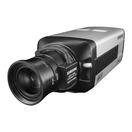
Network Camera SNC-570 2.1. Components and Accessories High Resolution, Day&Night Network Camera User’s Manual / CD / Quick Guide C-Mount adaptor Auto iris lens connection plug Cross Cable DC 12V Adapter / Power Cord... -
Page 25: Section Names And Functions
2.2. Section names and functions 2.2. Section names and functions 2.2.1. Front ① Lens cap Lens cap should be placed until the lens mounted. ② C-Mount lens adapter Mount the C-Mount lens on this adapter. ③ CS-Mount lens adaptor Replace the C-Mount lens adapter with this. ④... -
Page 26: Side
The camera controls the iris lens via this connector. ⑥ SD MEMORY CARD SLOT Insert the SD memory card here. SNC-570 is designed to accept SD card only, not for MMC. Do not insert the card in reverse, Caution otherwise the slot can be damaged. -
Page 27: Bottom
2.2. Section names and functions 2.2.3. Bottom ⑦ Tripod Mounting seat Bolt down the tripod here using screws specified as below. 1/4”-20UNC(20THREAD) L:4.5 ㎜±0.2 ㎜(ISO Standard), or 0.197’’(ASA Standard) ※ Tripod mounting module can be relocated to the top surface. In this case, use the screws shorter than 4 mm, otherwise the camera can be damaged seriously. -
Page 28: Back
Network Camera SNC-570 2.2.4. Back ⑧ Audio Terminal IN : Audio input terminal to connect microphone OUT: Audio output terminal to connect speaker system ⑨ Auto iris lens selector (switch) Select DC drive lens or Video drive lens with this switch. -
Page 29: Power Terminal
2.2. Section names and functions ⑫ ALARM terminal Alarm signal input terminal (I) is to connect to the external sensing devices such as infrared sensor, thermal sensor, etc. Alarm signal output terminal (O) is to connect to the external warning devices such as alarm light or siren, etc. ⑬... -
Page 30: Recommended Pc Specifications
Network Camera SNC-570 When you connect SNC-570 network camera to the PoE apparatus, the voltage transferred via Caution LAN cable may be abnormally high. Please contact to our distributor for installation or dismantling PoE system. 2.3. Recommended PC specifications Items... -
Page 32: Lens Installation
Network Camera SNC-570 3.1. Lens Installation Lenses are sold separately. Lenses such as an auto iris lens, CS- Mount lens and C-Mount lens can be used. To effectively realize major performance of this product, the use of DC format auto-iris lens is Caution recommended. - Page 33 3.1. Lens Installation 3. Please remove the cover of the auto iris lens connection plug and solder the lens cable to the connector pin in the plug. Lens Pin No VIDEO No.1 Pin Damping - Red(power) No.2Pin Damping + White No.3 Pin Drive + (video signal)
- Page 34 Network Camera SNC-570 When using a C-Mount lens Please take off the CCD protection cap and attach the C-Mount lens to the camera by screwing it in clockwise. When using a CS-Mount lens 1. Please attach the CS-Mount lens to the camera by screwing it in clockwise.
- Page 35 3.1. Lens Installation Please use the specified lens connection parts as shown in the picture below. The use of the wrong Caution sized parts of the wrong size may cause damage to the inside of the camera or result in poor fitting. Use of a lens which is too heavy affects the balance of the camera and may cause a malfunction.
-
Page 36: Connecting To Monitor
Network Camera SNC-570 3.2. Connecting to Monitor Please connect the video output terminal located on the back of the camera to the monitor. SNC-570 Network Camera Monitor The connection method varies depending on the type of monitor and accessories. Please refer to the user's manual for each instrument. -
Page 37: Connecting To Power
When using other adaptor not the adaptor (DC12V/4A) provided by the company, make sure that the specification is over AC 24V/1A or DC12V/2A. AC/DC Combined use In case of SNC-570, as recommended adaptor specification is over AC 24V/1A or DC12V/2A, please use surely the adaptor complying with this specifications. - Page 38 Network Camera SNC-570 Table 3-1. When the resistance value of copper wire is at [20℃(68℉)] Copper wire size (AWG) (0.22㎟) (0.33㎟) (0.52㎟) (0.83㎟) Resistance value 0.078 0.050 0.030 0.018 (Ω/m) Voltage drop(V/m) 0.028 0.018 0.011 0.06 As shown in the Table3-1, voltage decreases as the wire gets longer.
-
Page 39: Connection To External Control Connector
3.4. Connection to External Control Connector 3.4. Connection to External Control Connector The input order of terminal from left is Alarm input/Alarm output/Ground/RS-485 ‘+’signal/ RS-485 ‘-’signal. When connecting cable, push stripped part of electric wire in while pushing quadrangle button and take hands off from the button then the wire will be fixed. - Page 40 Network Camera SNC-570 Connecting Alarm Input This is the input terminal for external alarm signal, use it by connecting as following. DC+3.3V 카메라 내부 Camera Inside 47KΩ Alarm In CMOS Sensor CMOS 입력 Input 220Ω In case of selecting Normal Open at setup menu: In case of contact type, it is short and in case of active type, sensor input acts at “LOW”...
- Page 41 3.4. Connection to External Control Connector Connecting Alarm output This is the output terminal for external alarm signal, use it by connecting as following. Alarm Out Relay Relay Open Collector Relay 출력 2.2KΩ Output CMOS CMOS 출력 Output Relay 전원 Relay Power 10KΩ...
-
Page 42: Connecting Audio
Network Camera SNC-570 Connecting RS-485 ※ Connect the RS-485 to SRX-100B with the plus (+) signal to plus and minus (-) signal to minus. ※ The terminating resistance of the RS-485 can be set in the RS- 485 termination of the Basic menu. -
Page 43: Network Configuration And Connection Method Using Web Page
3.5. Network configuration and connection method using Web page 3.5. Network configuration and connection method using Web page Use when there is one SNC-570 network camera to be installed. 1. Please connect user’s PC to SNC-570 network camera using cross cable. - Page 44 Network Camera SNC-570 To configure network, the internal IP must be registered in the user’s PC. Note After pressing internet protocol (TCP/IP) properties, press the ‘advanced’ button to go into advanced configurations. Add with 192.168.1.XXX.
- Page 45 2. Please launch a Web browser on user’s PC and enter [192.168.1.100] in the URL address field and push <Enter> button. Connect to Webviewer login window of SNC-570 network camera. 3. Please login with administrator’s authorization and move to ‘Network’ page.(Default value for administrator login is ID:...
- Page 46 Network Camera SNC-570 Default value is ID: admin, PW: 11111111 Note 4. Please configure according to the network environment where SNC-570 network camera will be installed and push <Save> button to save the configuration.
- Page 47 3.5. Network configuration and connection method using Web page ① LAN / xDSL/ DHCP Configuration Item Description When network product is connected to normal LAN Use local LAN or when connected to static IP, the network data to be allotted to the IP is configured. When using xDSL dynamic IP, enter the ID and xDSL When automatically receiving IP through DHCP...
-
Page 48: Port Configuration
Network Camera SNC-570 ② Port Configuration Item Description connection port http, port Port Setting configurations can be set here and the DDNS use can be checked. Use DDNS changes its IP address every time the user attempts to connect to the ISP and when the product is connected to a cable modem or xDSL modem. -
Page 50: How To Use Web Viewer
Network Camera SNC-570 4.1. How to Use Web Viewer 4.1.1. Login To connect the login page, enter IP address of the camera on a internet Web browser and push enter key. Enter user ID and password and push <Login> button, then it move to related Web page. -
Page 51: Web Viewer Screen
4.1. How to Use Web Viewer 4.1.2. Web Viewer screen Web Viewer screen is composed of menu area for camera/video configuration and screen area for displaying input video from camera. Controls (Activated when Video Analytics is enabled) Video Analytics (Convert to Video Analytics mode) This button is activated when the Video Analytics Enable option is selected on the Video Analytics page. - Page 52 Network Camera SNC-570 RESET (Displayed when the Video Analytics mode is on) This sets the current screen image to the background. Alpha branding (Displayed when the Video Analytics mode is on) Makes changed parts appear half-transparent. It is not recommended to use alpha branding in Caution the low specification system.
- Page 53 4.1. How to Use Web Viewer Flip Image Turns the screen upside down. Stretch Image Expands the screen to the size of D1 when selecting CIF and QCIF for resolution. Save Image Saves the channel screen as a JPEG file. Compression Video compression mode (the mode of compressing video)
- Page 54 Network Camera SNC-570 Frame Rate - Setting on the Basic page The number of maximum video frame transmitted for each second. - 1, 5, 10, 15, 20, 25, 30 Quality - Setting on the Basic page Video quality - Very High, High, Normal, Low, Very Low Stops video for a while.
- Page 55 4.1. How to Use Web Viewer Camera Setup Displays OSD control button of camera. Camera OSD is displayed Day&Night configuration function Day&Night (Color, B/W configuration) PTZ control function PTZ Control...
- Page 56 Network Camera SNC-570 Instruction for Camera OSD control button <↑>, <↓> button Moves selection displaying arrows up and down on camera OSD menu. <←>, <→> button Changes configuration of selected field on camera OSD menu. <Set> button Displays camera OSD or moves to upper/lower menu of selected field.
-
Page 57: Using Administration Page
4.2. Using Administration page 4.2. Using Administration page 4.2.1. Initialization Screen after Connecting (Basic Screen) When connection is successful, the below screen will be displayed. -
Page 58: Live
Network Camera SNC-570 4.2.2. Live Please Move to Web Viewer page [Web Viewer live screen]... -
Page 59: Basic
4.2. Using Administration page 4.2.3. Basic Setup menu for basic configuration. Video/Audio Setup Item Description If you select the type of camera installed Video Format (NTSC or PAL), you can choose the size of the view on the camera. -
Page 60: Product Information
Network Camera SNC-570 Item Description Video compression type (This defines how the Compression Type video is compressed.) Initial Resolution Defines the size of the live screen view. Selects the video quality. You can still view Video Quality uninterrupted video with the quality reduced if you use a low speed Internet connection. -
Page 61: Network
4.2. Using Administration page 4.2.4. Network Network Configuration menu. -
Page 62: Network Configuration
Network Camera SNC-570 Network Configuration You can select LAN interface for static IP configuration, xDSL modem and DHCP for cable modem. Item Description Configure network assignment information of a camera connected to the local area network or to the static IP of xDSL modem. - Page 63 4.2. Using Administration page Streaming Engine Item Description RTSP/TCP Enable Determines whether to use RTSP/TCP. RTP/UDP Enable Determines whether to use RTP/UDP. RTP/Multicast Enable Determines whether to use RTP/Multicast. The default setting of Multicast IP is Streaming Image 224.0.1.1. Determines the resolution of the Streaming Resolution Engine.
- Page 64 Network Camera SNC-570 DDNS Usage Registration process of DDNS is as following Step1) Complete the registration form in iPOLiS website. The website is ‘www.samsungipolis.com’. Figure 1. Website of iPOLiS...
- Page 65 4.2. Using Administration page Figure 2. Membership Registration: SIGNUP Figure 3. Membership Registration: Input your information.
- Page 66 Network Camera SNC-570 Step2) Register the equipment after login. Figure 4. Login SNC-570 Figure 5. The list of registered equipment.
- Page 67 4.2. Using Administration page Figure 6. Product Registration. (Confirm repetition certainly at domain registration.) SNC-570 Figure 7. The list of registered equipment.
- Page 68 Click “USE DDNS” in order to do “Enable” and input the address of DDNS Server. (Default: www.samsungipolis.com ) Enter the ID and Password that is written when register product is in iPOLiS website. The Configuration of DDNS in SNC-570 is Completed.
- Page 69 4.2. Using Administration page Step4) Confirm the connection status of relevant product in product list of iPOLiS website. SNC-570 Figure 8. The List of Product. Be able to confirm the information of connected equipment if click <check> button of ‘Product information’.
- Page 70 Network Camera SNC-570 user SNC-570 Urban security Namsan Tower 2008-05-22 Figure 9. Product information Move to Login website of relevant product if click <view> button of ‘ view’. The buttons which are <Edit> and <Delete> of ‘product management’ move to relevant page through input password to item that fertilize or erase information of registered equipment in List of product.
- Page 71 4.2. Using Administration page How to use Streaming Engine We recommend VLC media player among Streaming Engine products. Step1) Network Page configuration Click the certain function of Streaming Engine and press <Save> button. - To update Network Page configuration, the system will reboot. Step2) VLC media player execution When you execute VLC media player, below screen capture will appear.
- Page 72 Network Camera SNC-570 RTP/TCP connection Select ‘Settings’ in the menu and click ‘Preferences...’ then check the ‘Advanced options’ box at the bottom of right side of the monitor, below options will appear.
- Page 73 4.2. Using Administration page Check the ‘Use RTP over RTSP (TCP)’. Enter ‘rtsp://[serverip]/mpeg4unicast’ in the RTSP URL and press <OK> button to connect to RTP/TCP. RTP Multicast connection Enter ‘rtsp://[serverip]/mpeg4unicast’ in the RTSP URL to connect to multicast. ※ TCP configuration should be cleared again to execute RTP Multicast.
-
Page 74: Video Analytics
Network Camera SNC-570 4.2.5. Video Analytics The Analytics feature compares the current screen against the one at the time of clicking on Set button and marks changed areas. It can detect up to 5 areas. Item Description Video Analytics Determines whether to use Video Analytics. - Page 75 4.2. Using Administration page Item Description This is the time needed to convert the current Reset Time screen to the standard one. (30 or 60 sec, 10 min, 30 min or ∞) Determines whether detect object, Stable Ratio depending on the size. (1:Low - 5:High) When Video Analytics is enabled, the motion detection feature is automatically disabled.
-
Page 76: Privacy
Network Camera SNC-570 4.2.6. Privacy For privacy protection, you can specify areas to hide. Item Description Grid Display Auto hide mode of screen split tool to select area. In the process of Privacy configuration, press <Select All> button to configure the whole screen or press <Deselect>... - Page 77 4.2. Using Administration page Item Description Blending Level function is to determine masking Blending transparency of excluded area in the range of 1 to Level 255. Level 255 is perfect transparent. Masking color can be selected among Grey, Blue Masking Color and Violet..
-
Page 78: Record (Using The Sd Memory)
Network Camera SNC-570 4.2.7. Record (Using the SD Memory) When Motion Detection, Video Analytics or Sensor is detected, you can save them. Then, if an Event is occurred, you can also watch them. Item Description SD Memory Size It shows total storage capacity of SD memory. - Page 79 4.2. Using Administration page Item Description Analytics Detection When Analytics is detected, you can save it. Recording Motion Detection When a motion is detected, you can save it Recording (MD). Sensor Detection When the Sensor detects a motion, you can Recording save it.
-
Page 80: User
Network Camera SNC-570 4.2.8. User This describes password change for administrator or user registration. Item Description Administrator Change password of administrator Password Change User clicks ‘Guest’ button to decide whether Guest Setup allowing guest to connect Main Viewer. You can register new user or delete, and set up user’s authority. - Page 81 4.2. Using Administration page ※ Set up user authority User’s authorities set up at ‘Current User’ are as follows. Catetory Description Use video related setup function Video (Compression, Resolution, Video Analytics) Control Pan, Tilt, Zoom, Audio output, Alarm output Audio Audio Input Whether relevant account is used (If not checked, not allowed log-in)
- Page 82 Network Camera SNC-570 Example 2) In case video function is limited (Do not check Video) ※ Compression, Resolution set up icon is inactivated.
-
Page 83: Pan/Tilt/Zoom
4.2. Using Administration page 4.2.9. Pan/Tilt/Zoom Configures PTZ Swing and Preset of the camera. Item Description PTZ Display Display PTZ menu. OSD Display Display OSD. Device ID Select an identification number of the camera. Model Select the model installed. When PTZ is enabled, the Video Analytics feature Caution may not function properly. -
Page 84: Motion Detection
Network Camera SNC-570 4.2.10. Motion Detection This sets up motion detection function of camera. Item Description Basic grid, used to choose area on the screen, is Grid Display displayed or hidden. When selecting motion detection area, click <Select Select Area All>... - Page 85 4.2. Using Administration page Item Description Setting up sensitivity to detect motion to adjust input MD Sensitivity video by situation. You can select 1-5, and 5 is the highest. When the motion detection feature is enabled, the Video Analytics feature is automatically Caution disabled.
-
Page 86: Alarm/Sensor
Network Camera SNC-570 4.2.11. Alarm/Sensor This sets up necessary information when using alarm function by attaching sensor to camera. - Page 87 4.2. Using Administration page Alarm/Sensor Setup ◊ Digital In Setup Item Description Sensor No. Shows the sensor number (Sensor1). Types of sensors are ‘Normal open’ and ‘Normal Sensor Type close.’ This selects up type of connected sensor. ◊ Digital Out Setup Item Description Set up Digital Out responding when event is...
- Page 88 Network Camera SNC-570 Item Description Recipient E-mail You can designate up to two e-mail Address 1 address receiving data when alarm Recipient E-mail occurs. Address 2 SMTP Server If you use an external E-mail server, Name enter the name of the E-mail server.
-
Page 89: Time
4.2. Using Administration page 4.2.12. Time Current Time Item Description Date Current setup date displayed Time Current setup time displayed Time Setup Item Description Set Manually Adjust time manually. Time Server Set up address of time server for Server 1 - 5. -
Page 90: Log
Network Camera SNC-570 4.2.13. LOG Recent activities made for camera are displayed as log. Item Description Lines Set up number of lines of the list. Log is viewed with number of lines you set up most View recently. Clear Delete logs. -
Page 91: Upgrade
Upgrade program of SNC-570 network camera. System Upgrade Configuration. Item Description SNC-570 Upgrades the firmware of the SNC-570 network Firmware camera. Factory Mode Setup If you click <Reset> button, server is returned to initial value when shipped from the factory after confirmation procedure by administrator. -
Page 92: System Reboot
Network Camera SNC-570 4.2.15. System Reboot Server is rebooted after confirmation procedure of administrator. Click <OK> button to reboot server. -
Page 94: Setup Menu
Network Camera SNC-570 5.1. Setup MENU Setup Menu LENS VIDEO MANUAL SHUTTER SENS-UP EXPOSURE RETURN MANUAL WHITE AWC→SET BALANCE OUTDOOR INDOOR BACKLIGHT SSNR DAY/NIGHT COLOR AUTO FREEZE V-REV H-REV IMAGE ADJUSTMENT D-ZOOM SHARPNESS RETURN CAMTITLE SYNC MOTION DET SPECIAL PRIVACY... -
Page 95: How To Set Up Functions
5.2. How to Set Up Functions 5.2. How to Set Up Functions Use OSD button displayed on Web Viewer screen to set up functions. : OSD button is popped up in Web Viewer. 1. Please press the <SET> button. Main setup menu is displayed on the monitor screen. MAIN SETUP ►... -
Page 96: Lens
Network Camera SNC-570 2. Select a desired function using the Up and Down buttons. Place the cursor over a desired item. 3. Set up a selected item by using the Left and Right buttons. 4. To finish the setting, select ‘EXIT’ and press the SET button. - Page 97 5.2. How to Set Up Functions MAIN SETUP ► 1. LENS 2. EXPOSURE 3. WHITE BAL 4. BACKLIGHT 5. SSNR 6. DAY/NIGHT AUTO 7. IMAGE ADJ 8. SPECIAL 9. EXIT DC/VIDEO: Auto iris lens selection When DC is selected, you can control screen brightness. The range of brightness control is between 1 and 70.
-
Page 98: Exposure
Network Camera SNC-570 the optimal value. Set AGC to OFF and adjust the Lens VR to an appropriate brightness. Adjust the Lens VR, adjust the BRIGHTNESS, and then check if the screen brightness changes properly. Otherwise, adjust the Lens VR again. - Page 99 5.2. How to Set Up Functions SHUTTER : You can select either auto or manual shutter. - A.FLK : Select this when you experience picture flicker, which can happen when there is a clash with the frequency of the installed lighting. - ESC : Select this to control the shutter speed automatically.
- Page 100 Network Camera SNC-570 - LOW : Allows automatic gain control from 0 to 30dB. - HIGH : Allows automatic gain control from 0 to 42dB. SENS-UP: When it is night or dark, the camera automatically detects the light level and maintains a clear picture if this mode is activated.
-
Page 101: White Balalace (White Bal.)
5.2. How to Set Up Functions 5.2.3. WHITE BALALACE (WHITE BAL.) Use the White Balance function to adjust the screen color. 1. When the SETUP menu screen is displayed, select ‘White Bal.’ by using the Up and Down buttons so that the arrow indicates ‘White Bal.’. - Page 102 Network Camera SNC-570 White Balance may not work properly under the following conditions. In this case select the AWC Caution mode. When the color temperature of environment surrounding the subject is out of the control range (e.g. clear sky, or sunset) When the ambient illumination of the subject is dim.
-
Page 103: Backlight
5.2. How to Set Up Functions 5.2.4. BACKLIGHT This camera is designed so that it delivers a distinctive subject and background at the same time, even when the subject is in backlight, unlike conventional cameras, by adopting a proprietary SV-IV DSP chip. - Page 104 Network Camera SNC-570 - Select WDR to adjust the WDR LIMIT and LEVEL. LIMIT: Adjust the WDR Sensitivity by selecting LOW, MIDDLE, or HIGH. LEVEL: Adjust the WDR Brightness by controlling the bar from 0 to 100. HLC (High Light Compensation) :...
- Page 105 5.2. How to Set Up Functions - HLC : Enable a user to select a mask color of high light area from a picture. OFF : Not being used. 3. Select a desired mode using the Left and Right buttons and press the SET button.
-
Page 106: Ssnr
Network Camera SNC-570 for the best WDR performance. If you increase LIMIT, the screen display may be distorted. For high performance of WDR function, using DC Iris lens rather than manual lens is recommended. Because there can be a difference in the... - Page 107 5.2. How to Set Up Functions MAIN SETUP 1. LENS 2. EXPOSURE 3. WHITE BAL 4. BACKLIGHT 5. SSNR ► 6. DAY/NIGHT AUTO 7. IMAGE ADJ 8. SPECIAL 9. EXIT 2. Select a desired mode using the Left and Right buttons. OFF: Deactivates SSNR.
-
Page 108: Day/Night
Network Camera SNC-570 5.2.6. DAY/NIGHT You can display pictures in color or black and white. 1. When the SETUP menu screen is displayed, select ‘DAY/NIGHT’ by using the Up and Down buttons so that the arrow indicates DAY/NIGHT. MAIN SETUP 1. - Page 109 5.2. How to Set Up Functions - DWELL TIME : You can select the duration time about changing the day/night mode. (5s, 7s, 10s, 20s, 30s, 40s, 60s) - DURATION : You can select brightness of illumination about changing the day/night mode. Color →...
-
Page 110: Image Adj
Network Camera SNC-570 5.2.7. IMAGE ADJ. 1. When the SETUP menu screen is displayed, select ‘IMAGE ADJ.’ by using the Up and Down buttons so that the arrow indicates IMAGE ADJ. MAIN SETUP 1. LENS 2. EXPOSURE 3. WHITE BAL 4. -
Page 111: Special
5.2. How to Set Up Functions RETURN : Select this to save the settings for the IMAGE ADJ. menu and to return to the SETUP menu. When H-REV or V-REV is selected, any text in the picture also will be flipped horizontally or Caution vertically. - Page 112 Network Camera SNC-570 MAIN SETUP 1. LENS 2. EXPOSURE 3. WHITE BAL 4. BACKLIGHT 5. SSNR 6. DAY/NIGHT AUTO 7. IMAGE ADJ 8. SPECIAL ► 9. EXIT 2. Select a desired mode using the Up and Down buttons. SPECIAL ►...
- Page 113 5.2. How to Set Up Functions When the CAM TITLE menu is ‘OFF’, no title will be displayed on the monitor screen even if you Caution enter one. SPECIAL ► 1. CAM TITLE 2. SYNC 3. MOTION DET 4. PRIVACY 5.
- Page 114 Network Camera SNC-570 If you move the cursor to CLR and press the <SET> button, all the letters are deleted. To edit a letter, change the cursor to the bottom left arrow Caution and press the <SET> button. Move the cursor...
- Page 115 5.2. How to Set Up Functions - Press the <SET> button. - You can select a desired phase from 0 to 359 when select 'phase'. - You can decide the synchronization between luminance and color signal when select the 'mode'. When using AC power at 60Hz frequency, you can use the L/L type synchronization.
- Page 116 Network Camera SNC-570 - YPOS : Determines the coordinate of the vertical axis for SEL POS. - XPOS : Determines the coordinate of the horizontal axis for SEL POS. - FILL→SET : Fills in a selected MD area. Fills in a selected MD area.
- Page 117 5.2. How to Set Up Functions - AREA SEL : You can select up to 8 MD areas. - AREA MODE: Determines whether to use the area selected in the AREA SEL, and the size and position of the area. - MASK COLOR : Determine area color.
-
Page 118: Exit
Network Camera SNC-570 5.2.9. EXIT Press the SET button in the EXIT menu to save the current settings and exit the SET menu. - Page 120 DC (VIDEO) when using a DC(VIDEO) lens. Open MS-DOS window to check whether SNC-570 network camera is connected to network. ※ In case of ping 192.168.1.100, replace it with IP address set up at server The video image is Please check if the lens is clean.
- Page 121 Troubleshooting Problem Solution There is a problem with camera Please check if an appropriate power operation. source to the camera complies with the The camera surface is too hot and black manufacturer's standard requirement, or stripes appear if the voltage keeps changing. the screen.
- Page 122 Please check audio driver is working in user’s PC. Please check whether network cable of Video is stopped SNC-570 network camera is correctly connected In case user uses hub or IP router, check whether these network equipments are working properly.
- Page 123 Troubleshooting Problem Solution Click ‘refresh (shortcut; F5) ’ button at No image from web viewer browser to recall the page Check whether power of camera and network cable is properly connected. Check whether computer is connected to network. If you use hub or router, check whether such equipments are properly operated.
-
Page 124: Specifications
Network Camera SNC-570 Specifications Model Name SNC-570N SNC-570P VIDEO Imaging Device 1/3" Vertical double density interline CCD Total Pixels 811(H) x 508(V) 795(H) x 596(V) Effective Pixels 768(H) x 494(V) 752(H) x 582(V) Scanning System 2:1 Interlace H:15.734 KHz/ H: 15.625 KHz/ Frequency V:59.94 Hz... - Page 125 Specifications Performance 704x480(D1), 704x576(D1), Resolution 352x240(CIF), 352x288(CIF), 176x120(QCIF) 176x144(QCIF) Compression MPEG-4/JPEG Dual CODEC with transcoder Up to 30fps @ Encode Rate Up to 25fps @ 704x576 Encoding 704x480 Transmission Up to 100Mbps speed Remote users 20 simultaneously Maximum RTP/UDP, RTP/Multicast, RTSP, TCP/IP, DHCP, Protocol DNS, DDNS, HTTP, SMTP, FTP, PPPoE and support...
- Page 126 Network Camera SNC-570 Install program Provided IP installer Provided Dedicated viewer Provided (SNM64) ActiveX controller Provided server General Input Voltage Dual (12V DC/ 24V AC), PoE (IEEE 802.3af) Power Consumption Max. 8.5W Operating Temperature/Humidity -10°C ~ +50°C / 30% ~ 80%RH Dimension(W×H×D)
-
Page 127: Dimension
Dimension Dimension... - Page 128 SAMSUNG TECHWIN SALES NETWORK SAMSUNG TECHWIN CO., LTD. SAMSUNG OPTO-ELECTRONICS UK, LTD. 145-3, Sangdaewon-dong, Jungwon-gu, Samsung House, 1000 Hillswood Drive, Seongnam-si, Gyeonggi-do 462-120, Korea Hillswood Business Park Chertsey, Surrey KT16 OPS Tel: +82-31-740-8151~8 Fax: +82-31-740-8145 Tel: +44-1932-45-5308 Fax: +44-1932-45-5325 SAMSUNG TECHWIN AMERICA,LTD.