
Related Manuals for Sony CNA-1


Summary of Contents for Sony CNA-1
- Page 1 CAMERA CONTROL NETWORK ADAPTOR CNA-1 OPERATION MANUAL [English] 1st Edition (Revised 1)
-
Page 2: Table Of Contents
Examples of system configurations........4 Supported devices ............8 Location and function of parts ..........8 Front panel ..............8 Rear panel ..............10 Starting and stopping the CNA-1 ........11 Menu operation ..............11 Menu operation from a web browser ......11 Menu configuration ............12 Transport Converting Function Setting ......18 Transport converting with LAN ........18... -
Page 3: Overview
MCS (multi- camera system) without using the MSU. CCA to LAN converting If you connect the CNA-1 to the camera network system via a LAN, and connect the CCU or RCP device to the CNA-1 with the CCA cable, you can add the... -
Page 4: Examples Of System Configurations
Examples of system configurations Example for the master device function The CNA-1 works as the master device for the MCS. CNA-1 Camera head MCS Mode: Client MCS Mode: Client Camera head MCS Mode: Client MCS Mode: Client Camera head MCS Mode: Client... - Page 5 MCS Mode: Client Camera head CCA-5 I/F CCA-5 I/F : LAN cable : CCA-5 cable CNA-1 setup For details of the following setting items, see “Menu items” (page 12). CNS Configuration CNS Mode Master Mode Disable Master IP Address Master MSU’s IP address...
- Page 6 Example for the Gateway function When controlling the Sony’s camera from the expansion control panel This is the MCS connection via the LAN. Note The expansion control panel needs to be compatible with the simple protocol provided from the CNA-1.
- Page 7 When controlling a expansion camera from the Sony’s control panel (MSU, RCP) This is the MCS connection via the LAN. Note The expansion camera needs to be compatible with the simple protocol provided from the CNA-1. MCS Mode: Client Expansion camera...
-
Page 8: Supported Devices
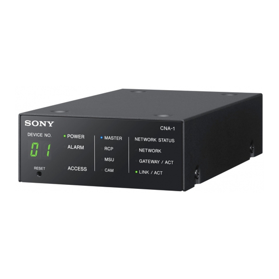
Off: The CNA-1 is working normally. Note If the ALARM indicator flashes even though the CNA-1 is not updating, immediately stop using the CNA-1, and consult your Sony Service Center. Location and function of parts... - Page 9 (camera or CCU) or the the Gateway Emulation mode. CNA-1 has failed to connect to it. Off: If the CNA-1 is set to the MCS Note mode, there is no master device or The MSU indicator works only if the...
-
Page 10: Rear Panel
Network link status indicator Note SPEED (green) Do not disconnect a USB mass On: The CNA-1 is linked to a 100 storage device while the ACCESS Mbps network. indicator is flashing. Off: The CNA-1 is linked to a 10... -
Page 11: Starting And Stopping The Cna-1
CNA-1 Menu operation from a web browser The menu for setting up the CNA-1 is The CNA-1 does not have the power operated on a PC via its web browser. button. When you connect the CNA-1 to • Supported OS: Windows 7 the power supply (CCU or hub that is •... -
Page 12: Menu Configuration
Only reloading the page on the browser Note does not update the values on the Status menu. When setting up the CNA-1, make sure to change the password from the factory setting. You can change the password on the Security menu. - Page 13 RESET switch. 2. Port Configuration Displays the status of the LAN setting. These settings are fixed. 3. Date and Time Sets the date and time of the CNA-1. Set the date. Set the time. Select the Time Zone. [Apply] button 4.
- Page 14 When the CNA-1 works in the MCS mode, the CNA-1 works as the master device by selecting [Enable]. When you use the CNA-1 as the client by selecting [Disable], input the IP address of the connected master device to [Master IP Address].
- Page 15 Gateway function or function. transport converting function. Input the IP address of the target CNA-1 for the transport converting function. Notes • Do not set the Gateway function to [Enable] when you do not plan to use it, because the Gateway function affects the other network device.
- Page 16 HD Cutout menu 1. HD Cutout Configuration For details, see “HD Cutout Control Input the IP address of the target Function Setting” (page 24). BPU for the HD Cutout control. [HD Cutout] tab Select [Enable] to use the HD Cutout control function. Adjust the smoothness of the movements for the cutout frame.
- Page 17 **You can input the multiple MAC Input the new password. addresses by separating with a new line. For example, 50:45:1F:34:0A:24 30:C0:07:AA:BF:17 Note If you have forgotten the password, reset the CNA-1 by pressing the RESET switch. Menu operation...
-
Page 18: Transport Converting Function Setting
CNA-1s is established with the simple camera protocol by converting the camera network system protocol to the simple When controlling a camera from the RCP in one-to-one CNA-1 (A) CNA-1 (B) CNS Mode: Legacy CNS Mode: Bridge Emulation Mode: Emulation Mode:... - Page 19 TCP Port Variable Emulation Mode Panel Active Function Disable Transport Converter Mode Enable Target IP Address IP address of the CNA-1 (B) Device setup for the network B CNA-1 (B) setup CNS Configuration CNS Mode Bridge Master Mode Disable Master IP Address...
- Page 20 When using the multi-camera system CNA-1 (A-1) CNS Mode: Legacy CNS Mode: Emulation Mode: CNA-1 (B-1) MCS/Master CNS Mode: MCS/Client Emulation Mode: Device No.: 1 CCU (1) CNS Mode: Legacy RCP (1) CNS Mode: MCS/Client Network Camera head CNA-1 (B-2)
- Page 21 IP address of the CNA-1 (A- CNA-1 (A-2) setup Gateway Configuration TCP Port TCP Port number of the CNA-1 (B-2) Target IP Address IP address of the CNA-1 (B- Other settings are the same as the CNA-1 (A-1) settings. Transport Converting Function Setting...
- Page 22 No need to input About the device number The device number that is set to the CNA-1 is recognized as the camera number on network B by the MSU/RCP. On the example above, the CNA-1 (B-1) is recognized as camera 1, and the CNA-1 (B-2) is recognized as camera 2.
-
Page 23: Transport Converting With Rs232/422
CNS Mode: Legacy CNS Mode: Bridge Network hub Camera head : LAN cable : CCA-5 cable CNA-1 (A) setup Gateway Configuration Transport Select RS232 or RS422 Bitrate, Date Bit, Parity Bit, Variable Stop Bit Target IP Address No need to input Other settings are the same as “Transport converting with LAN”... -
Page 24: Hd Cutout Control Function Setting
Set the network. 1. Connect the BPU and USB controller Connect the CNA-1 and BPU via LAN by using the PoE compatible network hub as in the illustration. Connect the USB controller to the CNA-1. For details about the usable USB controller, see “About the USB controller” (page 27). - Page 25 Note This setting is stored on the BPU. This setting is not stored on the CNA-1. 6. Set the parameters for the USB controller Set the parameters for the USB controller that is connected to the CNA-1 as necessary.
- Page 26 7. Assign the function to the buttons on the USB controller You can assign the function to the USB controller that is connected to the CNA-1 by using [Button Function Assignment]. Select the button function that is displayed in [Function Select], then click the [Assign] button.
-
Page 27: About The Usb Controller
Use the USB controller that is compliant with the USB HID device class. The following controller is recommended. 3D Mouse: 3D Connexion SpaceMouse Pro Up to two USB controllers can be connected to the CNA-1. When connecting two controllers, use the self-powered USB 2.0 compatible USB hub. Note The USB controller other than the recommended controller may not be recognized even if it is connected to the USB connector. -
Page 28: About The Gateway Function
Specifications Gateway function General Power requirements For details about using the Gateway PoE Class 2 function, consult your Sony service CCU PW (CCA) representative. DC: 10.5 V – 30 V EXT I/O (D-SUB) DC: 10.5 V – 17 V Power consumption... - Page 29 Design and specifications are subject to change without notice. Note Always verify that the unit is operating properly before use. SONY WILL NOT BE LIABLE FOR DAMAGES OF ANY KIND INCLUDING, BUT NOT LIMITED TO, COMPENSATION OR REIMBURSEMENT ON ACCOUNT OF...
-
Page 30: Notice Concerning Software Governed By The Gnu Gpl/Lgpl
For details about the license or list of the software packages, see System page > License information of the Web menu. To Obtain information on the source code and/or the source code for this software. Consult your nearest Sony Service. Notice Concerning Software Governed by the GNU GPL/LGPL... - Page 31 The material contained in this manual Trademarks consists of information that is the Windows and Internet Explorer are property of Sony Corporation and is registered trademarks of Microsoft intended solely for use by the Corporation in the United States and purchasers of the equipment described other countries.
- Page 32 Sony Corporation CNA-1 (SY) 4-431-096-02(1) ©2012...