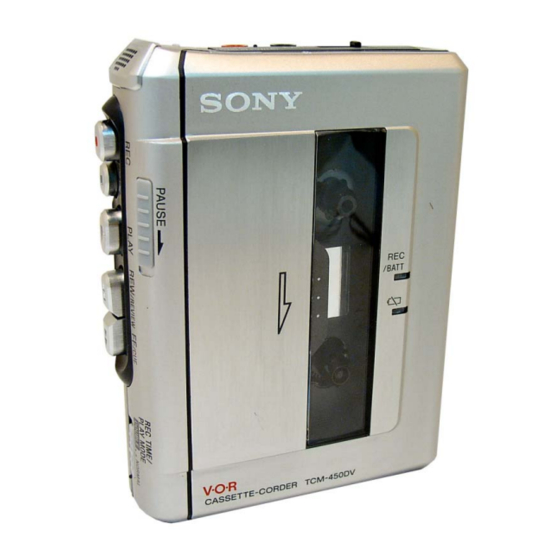
Sony TCM-450DV Service Manual
Cassette-corder
Hide thumbs
Also See for TCM-450DV:
- Operating instructions (2 pages) ,
- Specifications (2 pages) ,
- Operating instructions (2 pages)
Table of Contents
Advertisement
SERVICE MANUAL
Ver 1.1 2004. 05
Recording system
2-track 1 channel monaural
Speaker
Approx. 3.6 cm (1
7
⁄
in.) dia.
16
Tape speed
7
4.8 cm/s (1
⁄
ips) or 2.4 cm/s (
8
Variable range of the tape speed
From approx. +30% to –20% (with REC TIME/PLAY MODE
switch at "NORMAL")
Frequency range
250 - 6,300 Hz using nomal (TYPE I) cassette
(with REC TIME/PLAY MODE switch at "NORMAL")
Input
Microphone input jack (minijack/ monaural/PLUG IN POWER)
sensitivity 0.2 mV for 3 kΩ or lower impedance microphone
Output
Earphone jack (minijack/ monaural) for 8 - 300 Ω earphone
Power output (at 10 % harmonic distortion)
450 mW
Sony Corporation
9-877-551-02
Personal Audio Company
2004E02-1
Published by Sony Engineering Corporation
© 2004.05
TCM-450DV
SPECIFICATIONS
15
⁄
ips)
16
Model Name Using Similar Mechanism
Tape transport Mechanism Type
Power requirements
3 V DC, batteries R03 (AAA) x 2/
External DC 3 V power sources
Dimensions (w/h/d) (incl. projecting parts and controls)
Approx. 86.3 x 113.4 x 28.9 mm
1
1
3
(3
⁄
x 4
⁄
x 1
⁄
in.)
2
2
16
Mass (main unit only)
Approx. 173 g (6.2 oz.)
Supplied accessory
Carrying pouch (1)
Design and specifications are subject to change without notice.
CASSETTE-CORDER
US Model
Canadian Model
AEP Model
E Model
Chinese Model
Tourist Model
New
MT-450-175
Advertisement
Table of Contents

Related Manuals for Sony TCM-450DV

Summary of Contents for Sony TCM-450DV
- Page 1 0.2 mV for 3 kΩ or lower impedance microphone Output Earphone jack (minijack/ monaural) for 8 - 300 Ω earphone Power output (at 10 % harmonic distortion) 450 mW CASSETTE-CORDER Sony Corporation 9-877-551-02 Personal Audio Company 2004E02-1 Published by Sony Engineering Corporation © 2004.05...
-
Page 2: Table Of Contents
TCM-450DV SECTION 1 GENERAL TABLE OF CONTENTS This section is extracted from instruction manual. GENERAL ..............2 DISASSEMBLY ............3 Tape counter 2-1. Cabinet (Rear) ............3 reset button 2-2. Main Board ............. 4 2-3. Mechanism Deck (MT-450-175) ......4 Microphone 2-4. -
Page 3: Disassembly
TCM-450DV SECTION 2 DISASSEMBLY • This set can be disassembled in the order shown below. Belt (Counter), Belt (CAP) S, M901 (Capstan/reel motor), Cabinet (front) Mechanism deck Main board HRP901 (REC/PB head), HE901 (ERASE head) Cassette lid assy, LED board Cabinet (Rear) Note: Follow the disassembly procedure in the numerical order given. -
Page 4: Main Board
TCM-450DV 2-2. MAIN BOARD • On installation MAIN board, adjust the S301 and knob (pause). cabinet (front) knob (pause) 2 Remove solder (eight places) 1 Remove solder (three places) S301 7 MAIN board 5 screw (1.4 X 4.5) 3 screw (B1.7 X 9) 4 screw (1.4 X 3) -
Page 5: Belt (Counter), Belt (Cap)S, M901 (Capstan/Reel Motor), Hrp901 (Rec/Pb Head), He901 (Erase Head)
TCM-450DV 2-4. BELT (COUNTER), BELT (CAP) S, M901 (CAPSTAN/REEL MOTOR), HRP901 (REC/PB HEAD), HE901 (ERASE HEAD) 2 belt (CAP) S 1 belt (counter) 3 two screws (M1.4X1.4) 8 HE901 (ERASE head) 4 M901 (capstan/reel motor) 6 HRP901(REC/PB head) 7 screw (M1.4X4.5) 5 two screws (M1.4X1.4) -
Page 6: Mechanical Adjustments
TCM-450DV SECTION 3 MECHANICAL ADJUSTMENTS 1. Clean the following parts with a denatured-alcohol-moistened Torque Measurement swab: record/playback head pinch roller Mode Torque Meter Meter Reading erase head rubber belt 1.97 – 3.92mN•m capstan (20 – 40 g•cm) 2. Demagnetize the record/playback head with a head (0.28 –... -
Page 7: Diagrams
TCM-450DV SECTION 5 DIAGRAMS 5-1. BLOCK DIAGRAM S +1.7V REG. IC102 +VDD PRE AMP Q902 IC101 (1/2) POWER ON +VCC VOUT DETECT RFLT Q901 RIPPLE RFLT IN BTL POWER AMP FILTER IC101 (2/2) J101 PRE2 IN PRE OUT SP IN... -
Page 8: Printed Wiring Board -Main Section (Side A)
TCM-450DV 5-2. PRINTED WIRING BOARD – MAIN SECTION (SIDE A) – S301 • Semiconductor PAUSE . Location MAIN BOARD (SIDE A) Ref. No. Location NORMAL DOUBLE IC102 IC701 S601 REC TIME Q402 /PLAY MODE Q410 S602 S501 Q411 (FF/REW) Q412... -
Page 9: Printed Wiring Board -Main Section (Side B)
TCM-450DV PRINTED WIRING BOARD – MAIN SECTION (SIDE B) – • Semiconductor Location MAIN BOARD (SIDE B) Ref. No. Location D301 D302 D701 D702 D801 IC101 R315 Q305 C312 RV101 IC601 MIC1 Q301 R318 Q302 Q302 Q303 W104 C101 Q304... -
Page 10: Schematic Diagram -Main Section (1/2)
TCM-450DV 5-3. SCHEMATIC DIAGRAM – MAIN SECTION (1/2) –... -
Page 11: Schematic Diagram -Main Section (2/2)
TCM-450DV 5-4. SCHEMATIC DIAGRAM – MAIN SECTION (2/2) –... -
Page 12: Ic Block Diagrams
TCM-450DV Note on schematic diagrams • Voltages are taken with a VOM (Input impedance 10 MΩ). • WAVEFORMS • All capacitors are in µF unless otherwise noted. pF: µµF 50 WV or Voltage variations may be noted due to normal production toler- less are not indicated except for electrolytics and tantalums. -
Page 13: Exploded Views
TCM-450DV Ver 1.1 SECTION 6 EXPLODED VIEWS NOTE: • -XX, -X mean standardized parts, so they may • Hardware (# mark) list and accessories are have some differences from the original one. given in the last of this parts list. -
Page 14: Cabinet (Front) Section
TCM-450DV Ver 1.1 6-2. CABINET (FRONT) SECTION not supplied MIC1 Ref. No. Part No. Description Remarks Ref. No. Part No. Description Remarks 3-258-976-01 BUTTON (FF) X-3385-019-1 FRONT SUB ASSY, CABINET (AEP, EE) 3-258-977-01 BUTTON (REW) 3-258-985-01 SPRING (GROUND) 3-258-975-01 BUTTON (PLAY) -
Page 15: Mechanism Deck Section-1 (Mt-450-175)
TCM-450DV 6-3. MECHANISM DECK SECTION-1 (MT-450-175) HRP901 HE901 A (included in No.151) (included in No.151) supplied supplied M901 Ref. No. Part No. Description Remarks Ref. No. Part No. Description Remarks 3-703-816-08 SCREW (M1.4X1.4), SPECIAL HEAD 3-703-816-16 SCREW (M1.4X2.5), SPECIAL HEAD... -
Page 16: Mechanism Deck Section-2 (Mt-450-175)
TCM-450DV 6-4. MECHANISM DECK SECTION-2 (MT-450-175) supplied (Including A,109) Ref. No. Part No. Description Remarks Ref. No. Part No. Description Remarks X-3384-292-1 CHASSIS ASSY (ARO) (S) 3-229-064-01 WASHER, STOPPER 3-225-385-03 GEAR (B) 3-225-393-03 LEVER (SHUT/OFF) 3-229-063-01 SPRING (UD) (R), COMPRESSION... -
Page 17: Electrical Parts List
TCM-450DV Ver 1.1 SECTION 7 MAIN ELECTRICAL PARTS LIST NOTE: • Due to standardization, replacements in the • RESISTORS • Abbreviation parts list may be different from the parts All resistors are in ohms. CND: Canadian model specified in the diagrams or the components... - Page 18 TCM-450DV MAIN Ref. No. Part No. Description Remarks Ref. No. Part No. Description Remarks < JACK > R115 1-216-817-11 METAL CHIP 1/10W R118 1-216-813-11 METAL CHIP 1/10W J101 1-793-430-11 JACK, SMALL TYPE (MIC(PLUG IIN POWER)) R119 1-216-817-11 METAL CHIP 1/10W...
- Page 19 TCM-450DV Ver 1.1 MAIN Ref. No. Part No. Description Remarks Ref. No. Part No. Description Remarks R707 1-216-857-11 METAL CHIP 1/10W ACCESSORIES R708 1-216-825-11 METAL CHIP 2.2K 1/10W *********** R709 1-216-821-11 METAL CHIP 1/10W 3-220-749-21 CASE,CARRYING R712 1-216-853-11 METAL CHIP...
-
Page 20: Revision History
TCM-450DV REVISION HISTORY Clicking the version allows you to jump to the revised page. Also, clicking the version at the upper right on the revised page allows you to jump to the next revised page. Ver. Date Description of Revision 2004.01...