Sony CMT-A70 Service Manual
Personal component system
Hide thumbs
Also See for CMT-A70:
- Operating instructions manual (48 pages) ,
- Specification (2 pages) ,
- Limited warranty (1 page)
Table of Contents
Advertisement
SERVICE MANUAL
Ver. 1.2 2006.02
US and foreign patents licensed from Dolby Laboratories.
AUDIO POWER SPECIFICATIONS
(US model only)
POWER OUTPUT AND TOTAL HARMONIC
DISTORTION
With 6 Ω loads, both channels driven from 100 -
10,000 Hz; rated 55 W per channel-minimum
RMS power, with no more than 10 % total
harmonic distortion in AC operation.
CD player section
System
Compact disc digital audio system
Laser diode properties
Material: GaAlAs
Wave length: 780 nm
Emission duration: Continuous
Laser output: Less than 44.6 µW
(This output is the value measured at a distance of about
200 mm from the objective lens surface on the optical
pick-up block with 7 mm aperture.)
Spindle speed
400 r/min (rpm) to 1 000 r/min (rpm) (CLV)
Number of channels
2
Frequency response
20 - 20 000 Hz +0/–1 dB
Wow and flutter
Below measurable limit
Radio section
Frequency range
FM 87.5 - 108 MHz
AM
US, Canadian models: 530 - 1 710 kHz
Other models: 531 - 1 611 kHz (9 kHz step)
530 - 1 610 kHz (10 kHz step)
IF
FM: 10.7 MHz
AM: 450 kHz
Sony Corporation
9-879-211-03
Personal Audio Division
2006B05-1
Published by Sony Techno Create Corporation
© 2006.02
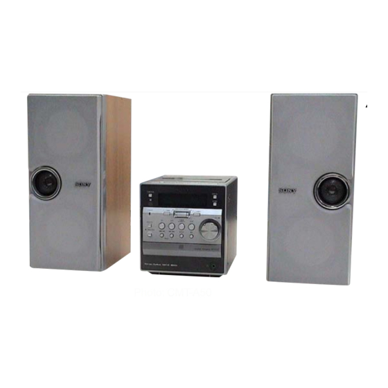
CMT-A50/A70
Photo: CMT-A50
Model Name Using Similar Mechanism
CD
CD Mechanism Type
Section
Optical Pick-up Block Name
Optical Pick-up Name
Tape deck
Model Name Using Similar Mechanism
Section
Tape Transport Mechanism Type
SPECIFICATIONS
Aerials
FM: Lead aerial
AM: Loop aerial
Cassette-corder section
Recording system
4-track 2 channel stereo
Fast winding time
Approx. 112 s (sec.) with Sony cassette C-60
Frequency response
TYPE I (normal): 50 - 15 000 Hz
General
Speaker
Tweeter: 4 cm dia., 6 Ω
Woofer: 13 cm dia., 6 Ω
Passive radiator: 10 cm dia. (CMT-A50 only)
Input
LINE IN jack (stereo minijack)
Minimum input level 430 mV
Outputs
Headphones jack (stereo minijack):
For 8 - 64 Ω impedance headphones
OPTICAL DIGITAL OUT (CD) (optical output
connector):
Wavelength: 630 - 690 nm
Maximum power output
CMT-A50: 20 W
CMT-A70: 60 W
Power requirements
For personal component system:
US, Canadian models: 120 V AC, 60 Hz
Korean model: 220 V AC, 60 Hz
Other models: 230 V AC, 50 Hz
PERSONAL COMPONENT SYSTEM
US Model
Canadian Model
Australian Model
AEP Model
UK Model
CMT-A50/A70
E Model
NEW
FLM-A50
KSM-213CCP or KSM-213RCP
KSS-213C or KSS-213R
NEW
CMAL1Z252A
For remote control:
3 V DC, 2 R03 (size AAA) batteries
Power consumption
CMT-A50: 50 W
CMT-A70: 100 W
Dimensions
Player:
Approx. 136 × 151.8 × 204 mm (w/h/d)
(incl. projecting parts)
Speaker:
CMT-A50: Approx. 128 × 287 × 215 mm (w/h/d)
(incl. projecting parts)
CMT-A70: Approx. 164 × 267 × 255 mm (w/h/d)
(incl. projecting parts)
Ma
CMT-A50:
Player: Approx. 1.6 kg
Left speaker: Approx. 4.3 kg
Right speaker: Approx. 2.2 kg
CMT-A70:
Player: Approx. 1.6 kg
Left speaker: Approx. 5.6 kg
Right speaker: Approx. 2.9 kg
Supplied accessories
Remote control (1)
FM lead aerial (1)
AM loop aerial (1)
CD-ROM (SonicStage) (1)
SonicStage Installation/Operating Guide (1)
Design and specifications are subject to change without
notice.
CMT-A70
CMT-A50
Advertisement
Table of Contents

Related Manuals for Sony CMT-A70


Summary of Contents for Sony CMT-A70
-
Page 1: Specifications
CMT-A50: Approx. 128 × 287 × 215 mm (w/h/d) TYPE I (normal): 50 - 15 000 Hz (incl. projecting parts) CD player section CMT-A70: Approx. 164 × 267 × 255 mm (w/h/d) General System (incl. projecting parts) Compact disc digital audio system... - Page 2 FONCTIONNEMENT. NE REMPLACER CES COM- POSANTS • Usable with ordinary solder QUE PAR DES PIÈCES SONY DONT LES NUMÉROS SONT It is best to use only unleaded solder but unleaded solder may DONNÉS DANS CE MANUEL OU DANS LES SUPPLÉMENTS also be added to ordinary solder.
-
Page 3: Table Of Contents
– AMP Section (CMT-A70 only) – ......... 36 6-17. Schematic Diagram – AMP Section (CMT-A70 only) – ......... 37 6-18. Printed Wiring Board – POWER SUPPLY Section (CMT-A70 only) – .... 38 6-19. Schematic Diagram – POWER SUPPLY Section (CMT-A70 only) – .... 39... -
Page 4: Servicing Notes
Korean model AC: 220V-60Hz 50W US and Canadian model AC: 120V 60Hz 100W AEP, UK, Italian, CMT-A70 East European, Russian AC: 230V-50Hz 100W and Australian models HOW TO OPEN THE CD TRAY WHEN POWER SWITCH TURNS OFF. 2 Pull-out the CD tray. - Page 5 CMT-A50/A70 HOW TO IDENTIFY KSM-213CCP AND KSM-213RCP There is gear cover. There is not gear cover. Changing the resume Adjusting the contrast play setting of the display The player is initially set to start playback from the point you last stopped playing Jog dial (PUSH (resume play) ENTER/...
-
Page 6: General
CMT-A50/A70 SECTION 2 This section is extracted from instruction manual. GENERAL Basic Operations Playing a CD Press CD u (u on the remote). 1, 2 The player plays all the tracks once. Display ATRAC CD/MP3 CD** Audio CD Track name* File name Track number Playing time... -
Page 7: Listening To The Radio
CMT-A50/A70 Listening to the radio Use these buttons for additional operations VOLUME MODE/DIR Tips Do this • If the FM broadcast is adjust the volume Turn the VOLUME control. (Press noisy, press MODE/DIR VOL +*, – on the remote.) (MODE on the remote) repeatedly until “Mono”... -
Page 8: Setting The Clock
CMT-A50/A70 The Timer Note Setting the clock If you disconnect the AC power cord, the clock display may return to “– –:– –”. In this case set the “– –:– –” indicator appears on the display clock again. until you set the clock. Jog dial The time display system of this player is the 12- (PUSH ENTER/... -
Page 9: Disassembly
CMT-A50/A70 SECTION 3 DISASSEMBLY • This set can be disassembled in the order shown below. 3-1. DISASSEMBLY FLOW Note 1: The process described in can be performed in any order. Note 2: Without completing the process described in , the next process can not be performed. 3-2. -
Page 10: Cabinet Rear
CMT-A50/A70 Ver. 1.1 Note: Follow the disassembly procedure in the numerical order given. 3-2. CABINET REAR 1 screw (BVTP3 × 6) 2 three screws (BVTP3 × 10) 7 two screws 6 two stickets 1 screw (BVTP3 × 6) 8 cabinet rear 3 two screws (BVTP3 ×... -
Page 11: Cd Mechanism Deck (Flm-A50)
CMT-A50/A70 3-4. CD MECHANISM DECK (FLM-A50) 4 CD mechanism deck 2 connector (FLM-A50) (CN310) 2 connector (CN306) 1 flexible flat cable (29 core) (CN702) 3 two screws (BVTP3 × 10) 3-5. SUB BOARD 4 SUB board 1 screw (BVTP3 × 8) 2 harness 3 connector (CN309) -
Page 12: Top Case Assy
CMT-A50/A70 3-6. TOP CASE ASSY 4 top case assy 3 boss 2 connector (CNP304) 3 boss 1 flexible flat cable (8 core) (CN303) 2 connector (CN302) 3-7. MAIN BOARD 2 connector 2 connector (CN306) (CN310) 3 claw 4 MAIN board 1 flexible flat cable (29 core) (CNF307) 3 claw... -
Page 13: Cd Board
CMT-A50/A70 3-8. CD BOARD 4 wire (flat type) (16 core) (CN701) 5 CD board 2 screw 1 Remove four solders. 3-9. TRAY 1 two screws (P2.6 × 8) 2 chuck plate assy gear 6 tray 5 two claws 3 Rotate the gear in the direction of arrow. -
Page 14: Optical Pick-Up Block (Ksm-213Ccp Or Ksm-213Rcp)
CMT-A50/A70 Ver. 1.1 3-10. OPTICAL PICK-UP BLOCK (KSM-213CCP or KSM-213RCP) 5 two bosses 8 vibration proof 6 arm rubber (red) 1 two screws (PWH2.6 × 10) 7 vibration proof 8 vibration proof rubber (green) rubber (red) 4 two screws (PWH2.6 × 10) 9 optical pick-up block (KSM-213CCP or KSM-213RCP) 2 screw... -
Page 15: Optical Pick-Up (Kss-213R)
CMT-A50/A70 3-12. OPTICAL PICK-UP (KSS-213R) 1 gear (B) 5 optical pick-up (KSS-213R) 4 sled shaft 2 two screws (M2) 3-13. TAPE MECHANISM DECK (CMAL1Z252A) 2 Open the top case. 6 tape mechanism deck (CMAL1Z252A) 5 head shield 1 four screws (BVTP3 ×... -
Page 16: Test Mode
CMT-A50/A70 SECTION 4 TEST MODE CD TEST MODE Releasing The CD Test Mode To release this mode, press the [DISPLAY] button for to seconds in Entering The CD Test Mode the mode of STOP1, STOP2 or STOP3. Or disconnect the AC plug. Procedure: button to turn the power on, and [FUNCTION] 1. - Page 17 CMT-A50/A70 DISPLAY TEST MODE Procedure: 1. Press the button to turn the power on. , [MODE/DIR] and [TIMER] 2. Press the three buttons of simultaneously. 3. Enter the Display Test Mode and display the version of microcomputer (IC309 on the MAIN board) for 10 seconds. 4.
-
Page 18: Electrical Adjustments
CMT-A50/A70 SECTION 5 ELECTRICAL ADJUSTMENTS Adjustment Location: DECK SECTION 0 dB = 0.775 V – MAIN BOARD (Component Side) – • Precaution 1. The adjustment should be performed with the rated power supply voltage. 2. The adjustments should be performed for both L-ch and R-ch. REC BIAS ADJUSTMENT Procedure: RV201... -
Page 19: Cd Section
CMT-A50/A70 Checking Location: CD SECTION – CD Board (Conductor Side) – Note: 1. Perform all CD section check in the CD Test Mode. (Refer to page 16) 2. Use the PATD-012 disc (Part No.: 4-225-203-01). 3. Use an oscilloscope with more than 10 MΩ impedance. 4. -
Page 20: Diagrams
CMT-A50/A70 SECTION 6 DIAGRAMS 6-1. BLOCK DIAGRAM – SERVO Section – OPTICAL PICK-UP RF AMP, FOCUS/TRACKING BLOCK ERROR AMP CD DSP (KSS-213C) IC701 IC702 CD-L RF AC RFAC (Page 21) AOUT1 CD +3.3V RFDC RFDC AOUT2 R-CH J302 RFDCI OPTICAL DIGITAL DOUT OUT (CD) -
Page 21: Block Diagram - Main Section
Q303, 305 TU +9V R-CH Q513 – 515 RDS +3.3V MD IN L MUTING IC501 (CMT-A50) CONTROL IC501 (CMT-A70) Q323, 324 CD IN L TONE OUT L VOL IN L VOL OUT L 33 POWER AMP (L-CH) FM 75Ω FM ANT... -
Page 22: Block Diagram - Panel, Power Supply Section
CMT-A50/A70 Ver. 1.2 6-3. BLOCK DIAGRAM – PANEL, POWER SUPPLY Section – SYSTEM CONTROLLER IC309 (3/3) LCD_AD0 - LCD_AD7 LIQUID CRYSTAL DISPLAY LCD701 90 LCD_AO 88 LCD-CS 89 LCD-RES 91 LCD-WR B+ SWITCH TU +9V Q327 B+ SWITCH RDS +3.3V Q328 LED DRIVE D702, 703... - Page 23 • Waveforms are taken with a oscilloscope. Voltage variations may be noted due to normal produc- tion tolerances. • Circled numbers refer to waveforms. – Speaker unit (L-CH) (CMT-A50) – – Speaker unit (L-CH) (CMT-A70) – • Signal path. : TUNER : TAPE PLAY AMP board...
-
Page 24: Printed Wiring Board - Cd Board
CMT-A50/A70 • See page 23 for Circuit Boards Location. 6-4. PRINTED WIRING BOARD – CD Board – : Uses unleaded solder. • Semiconductor Location Ref. No. Location CD BOARD CD BOARD (CONDUCTOR SIDE) (COMPONENT SIDE) IC701 E-11 IC702 G-11 IC703 I-12 C772 IC704... -
Page 25: Schematic Diagram - Cd Board
CMT-A50/A70 • See page 40 for Waveforms. • See page 40 for IC Block Diagrams. • See page 45 for IC Pin Function Description. 6-5. SCHEMATIC DIAGRAM – CD Board – FB712 ON/OFF C748 +1.5V REGULATOR FB704 FB705 FB709 C715 AOUT2 AOUT1 0.01... -
Page 26: Main Board (Component Side)
CMT-A50/A70 Ver. 1.2 • See page 23 for Circuit Boards Location. 6-6. PRINTED WIRING BOARD – MAIN Board (Component Side) – : Uses unleaded solder. MAIN BOARD (COMPONENT SIDE) 1-864-630- (13) CMT-A50/A70... -
Page 27: Printed Wiring Board - Main Board (Conductor Side)
CMT-A50/A70 Ver. 1.2 • See page 23 for Circuit Boards Location. 6-7. PRINTED WIRING BOARD – MAIN Board (Conductor Side) – : Uses unleaded solder. • Semiconductor Location Ref. No. Location LOADING BOARD TOP KEY BOARD D301 CN651 CN704 (Page 32) (Page 32) D302 D304... -
Page 28: Schematic Diagram - Main Board (1/2)
CMT-A50/A70 Ver. 1.2 • See page 40 for Waveforms. • See page 40 for IC Block Diagrams. 6-8. SCHEMATIC DIAGRAM – MAIN Board (1/2) – (1/2) CNF301 (US,CND,KR,AUS) (AEP,UK,IT,EE,RU) FB202 ANTENNA C215 R230 C216 R231 R233 RDS DATA 10 50V 4.7k 470p C230... -
Page 29: Schematic Diagram - Main Board (2/2)
CMT-A50/A70 Ver. 1.2 • See page 40 for Waveforms. • See page 40 for IC Block Diagrams. • See page 45 for IC Pin Function Description. 6-9. SCHEMATIC DIAGRAM – MAIN Board (2/2) – (Page 28) (2/2) R319 Q314,315 R320 TRIGGER PLUNGER DRIVE Q314... -
Page 30: Printed Wiring Boards - Regulator Section
CMT-A50/A70 Ver. 1.2 • See page 23 for Circuit Boards Location. 6-10. PRINTED WIRING BOARDS – REGULATOR Section – : Uses unleaded solder. • Semiconductor Location – Except US, CND models – Ref. No. Location (A50) (A70) D318 D319 AMP BOARD AMP BOARD D320 CN501, 502... -
Page 31: Schematic Diagram - Regulator Section
CMT-A50/A70 Ver. 1.2 6-11. SCHEMATIC DIAGRAM – REGULATOR Section – (US,CND) (EXCEPT US,CND) +10V REGULATOR IC306 +10V REGULATOR TA7810S IC306 TA7810S CN316 C363 D320 C361 C362 D321 1N4002B 1N4002B +7V REGULATOR (EXCEPT US,CND) IC307 +7V REGULATOR TA7807S IC307 D322 CN317 TA7807S 1N4002B C367... -
Page 32: Printed Wiring Boards - Panel, Motor Section
CMT-A50/A70 • See page 23 for Circuit Boards Location. 6-12. PRINTED WIRING BOARDS – PANEL, MOTOR Section – : Uses unleaded solder. TOP KEY BOARD CN704 S762 MAIN BOARD C754 TIMER S764 S765 CNP304 S766 STANDBY S763 (Page 27) SLEEP R765 R766 R762... -
Page 33: Schematic Diagram - Panel, Motor Section
CMT-A50/A70 • See page 40 for IC Block Diagrams. 6-13. SCHEMATIC DIAGRAM – PANEL, MOTOR Section – CNF701 D701 LOADING MOTOR SLR-342VCT31 DRIVE STANDBY R701 IC651 BA6208 Q701 KRC102M-AT D702 UB3803X-J582K DRIVE LCD701 R702 M651 LIQUID D702,703 C656 CN651 (LOADING) CRYSTAL (LCD BACK LIGHT) C651... -
Page 34: Printed Wiring Boards - Amp, Power Supply Section (Cmt-A50 Only)
CMT-A50/A70 Ver. 1.2 • See page 23 for Circuit Boards Location. 6-14. PRINTED WIRING BOARDS – AMP, POWER SUPPLY Section (CMT-A50 only) – : Uses unleaded solder. AMP BOARD T602 SUB POWER TRANSORMER POWER OUT TO MAIN UNIT SUB BOARD CN312 (Page 30) T601... -
Page 35: Schematic Diagram - Amp, Power Supply Section (Cmt-A50 Only)
CMT-A50/A70 Ver. 1.2 • See page 40 for IC Block Diagrams. 6-15. SCHEMATIC DIAGRAM – AMP, POWER SUPPLY Section (CMT-A50 only) – POWER AMP IC501 STK453-030S C537 R510 C508 0.47 470p D504 Q502,511 1SS133T-77 R568 MUTING R558 2.2k C525 R547 Q502 Q511 DTC343TS-TP... -
Page 36: Printed Wiring Boards - Amp Section (Cmt-A70 Only)
CMT-A50/A70 Ver. 1.2 • See page 23 for Circuit Boards Location. 6-16. PRINTED WIRING BOARDS – AMP Section (CMT-A70 only) – : Uses unleaded solder. • Semiconductor Location Ref. No. Location D501 AMP BOARD THERMISTER BOARD D502 D503 R558 R505... -
Page 37: Schematic Diagram - Amp Section (Cmt-A70 Only)
CMT-A50/A70 Ver. 1.2 • See page 40 for IC Block Diagrams. 6-17. SCHEMATIC DIAGRAM – AMP Section (CMT-A70 only) – FAN + M501 FAN - (FAN) FAN + CN506 CNP507 POWER AMP THP501 IC501 STK433-070 CN507 R568 4.7k R567 D518... -
Page 38: Printed Wiring Board - Power Supply Section (Cmt-A70 Only)
CMT-A50/A70 Ver. 1.2 • See page 23 for Circuit Boards Location. 6-18. PRINTED WIRING BOARD – POWER SUPPLY Section (CMT-A70 only) – : Uses unleaded solder. • Semiconductor Location Ref. No. Location POWER BOARD D505 D506 D507 D508 D513 D514... -
Page 39: Schematic Diagram - Power Supply Section (Cmt-A70 Only)
CMT-A50/A70 Ver. 1.2 6-19. SCHEMATIC DIAGRAM – POWER SUPPLY Section (CMT-A70 only) – CN603 D506 1SS133T-77 POWER DET +14V T601 UREG GND MAIN POWER F601 T5AL TRANSFORMER +VCC 250V +VCC UNREG GND C603 UNREG GND UNREG GND D601 UNREG GND... - Page 40 CMT-A50/A70 • Waveforms • IC Block Diagrams – CD Board – – MAIN Board – – CD Board – IC701 CXA2647N-T4 IC701 qg (RFAC) IC703 wl (EXTAL) T301 4 (REC mode) (CD play mode) (MP3 play mode) ROM/RW DC OFST RFDCI –...
- Page 41 CMT-A50/A70 IC703 CXR710160-209R 64 63 62 61 60 59 58 57 56 55 52 51 50 49 PE3/RxD1 PE2/TxD1 PE1/RxD0 PE0/TxD0 INTERFACE LRCKI BCKI VDIOCD0 PCMDI DVDD4 CD-ROM TEST8 INTERFACE TEST7 DVDD0 DVSS0 DVSS2 VDIO0 DVDD2 VDIOCD1 PC3/SCS0 PF4/XRDE PC2/SI0 PI3/BCKO INTERRUPT CONTROLLER PC1/SO0...
- Page 42 CMT-A50/A70 IC704 BA5946FP-E2 INTERFACE LEVEL SHIFT MUTE THERNAL SHUTDOWN INTERFACE INTERFACE IC706 S-T111B15MC-OGATFG VOUT ON/OFF OVER CURRENT PROTECTOR ON/OFF REFERENCE VOLTAGE CIRCUIT CIRCUIT...
- Page 43 CMT-A50/A70 – MAIN Board – IC301 BD3402KS2 56 55 54 53 52 51 48 NC 47 NC 46 NC 45 NC 44 BNF1 43 BOUT1 − 42 BOUT2 41 BNF2 INPUT SELECT − PBNF2 PBOUT2 BUFFER 40 NC PBOUT1 − TONE 39 TONE OUT2 CONTROL...
- Page 44 CMT-A50/A70 IC311 S-816A33AMC-BAI-T2-G REFERENCE ERROR SINK VOLTAGE DRIVER OVERCURRENT SOURCE PROTECT POWER CIRCUIT SUPPLY – AMP Board – – LOADING Board – IC502 RT8H015C-T112-1 IC651 BA6208 MOTOR SWITCH DRIVE MOTOR SWITCH OVER LOAD DRIVE DETECT DETECT...
- Page 45 CMT-A50/A70 • IC Pin Function Description CD BOARD IC702 CXD3029R (CD DSP) Pin No. Pin Name Description XRAS Row address strobe signal output to the D-RAM Data input enable signal output to the D-RAM 3 to 6 D1, D0, D3, D2 Two-way data bus with the D-RAM 7, 8 TEST1, TEST2...
- Page 46 CMT-A50/A70 Pin No. Pin Name Description 53, 54 AVSS1, AVSS2 Ground terminal VREFR R-ch reference voltage output terminal AOUT2 R-ch analog audio signal output terminal AVDD2 Power supply terminal (+3.3V) TES1 Input terminal for the test (fixed at "L") TEST Input terminal for the test (fixed at "L") VSS1 Ground terminal...
- Page 47 CMT-A50/A70 Pin No. Pin Name Description TRDR Tracking servo drive signal (-) output to the coil/motor drive TFDR Tracking servo drive signal (+) output to the coil/motor drive SRDR Sled servo drive signal (-) output to the coil/motor drive SFDR Sled servo drive signal (+) output to the coil/motor drive SSTP Disc inner position detection signal input terminal...
- Page 48 CMT-A50/A70 MAIN BOARD IC309 MB90474PF-G-202-BNDE1 (SYSTEM CONTROLLER) Pin No. Pin Name Description CD_FOK Focus OK signal input terminal CD_GFS GFS signal input terminal CD_XRST System reset signal output to the CD DSP CD_RW/ROM CD-RW/CD-ROM switching signal output terminal CD_PWM RF RF offset cancel PWM ouput terminal CD_PWM TE TE offset cancel PWM ouput terminal...
- Page 49 CMT-A50/A70 Pin No. Pin Name Description PSTBY Standby on/off control signal output to the power amplifier 49 to 51 MD0 to MD2 Setting terminal for the CPU operational mode CD_RDEN Interrupt status input from the MP3 decoder SHIFT CLOCK Shift clock control signal output terminal "H": shift AC-CHK AC detection signal input terminal R-DATA (O)
-
Page 50: Exploded Views
CMT-A50/A70 Ver. 1.2 SECTION 7 EXPLODED VIEWS NOTE: • Items marked “*” are not stocked since they • -XX and -X mean standardized parts, so they The components identified by mark may have some difference from the original are seldom required for routine service. Some 0 or dotted line with mark 0 are one. -
Page 51: Front Panel Section
CMT-A50/A70 Ver. 1.2 7-2. FRONT PANEL SECTION LCD701 KEY boad supplied not supplied Ref. No. Part No. Description Remark Ref. No. Part No. Description Remark 2-186-716-01 MAIN COVER (A50: AEP, UK, IT, EE, RU) 2-186-718-01 SOUND BUTTON 2-186-716-11 MAIN COVER (A70: AEP, UK, IT, EE, RU) 3-921-725-01 SCREW (2.6X10), +PWH 2-186-716-21 MAIN COVER (A50: KR) A-1077-598-A JACK BOARD, COMPLETE... -
Page 52: Top Case Section
CMT-A50/A70 Ver. 1.2 7-3. TOP CASE SECTION not supplied not supplied Ref. No. Part No. Description Remark Ref. No. Part No. Description Remark 1-796-351-81 MECHANISM, SIGNAL CASSETTE 2-179-025-21 CASSETTE HOLDER (CMAL1Z252A) (A70: CND, AEP, UK, IT, EE, RU, AUS) 4-231-836-01 SPRING (HEART CAM-A) 4-231-824-01 CAM (A), HEART 3-047-468-01 DAMPER A-1077-600-A TOP KEY BOARD, COMPLETE... -
Page 53: Cd Mechanism Deck Section (Flm-A50)
CMT-A50/A70 Ver. 1.2 7-4. CD MECHANISM DECK SECTION (FLM-A50) optical pick-up section (KSS-213CCP or KSM-213RCP) not supplied not supplied M651 Ref. No. Part No. Description Remark Ref. No. Part No. Description Remark 3-028-010-02 TRAY 2-548-813-01 TUNER SHIELD 3-028-019-11 PLATE, CHUCK 3-028-014-01 GEAR 1-452-899-21 MAGNET 3-933-020-01 BELT... -
Page 54: Optical Pick-Up Section (Ksm-213Ccp)
CMT-A50/A70 Ver. 1.2 7-5. OPTICAL PICK-UP SECTION (KSM-213CCP) Note: Refer to “HOW TO IDENTIFY KSM-213CCP AND KSM-213RCP” in the SERVICING NOTES (page 5) for how to identify KSM-213CCP and KSM-213RCP. not supplied not supplied M702 (spindle) M701 The components identified by Les composants identifiés par une mark 0 or dotted line with marque 0 sont critiques pour la... -
Page 55: Optical Pick-Up Section (Ksm-213Rcp)
CMT-A50/A70 Ver. 1.2 7-6. OPTICAL PICK-UP SECTION (KSM-213RCP) Note: Refer to “HOW TO IDENTIFY KSM-213CCP AND KSM-213RCP” in the SERVICING NOTES (page 5) for how to identify KSM-213CCP and KSM-213RCP. (including M701 (spindle)) not supplied M702 (spindle) not supplied M701 The components identified by Les composants identifiés par une mark 0 or dotted line with... -
Page 56: Speaker (Left) Section (A50)
CMT-A50/A70 Ver. 1.2 7-7. SPEAKER (LEFT) SECTION (A50) T601 not supplied not supplied (SPK board) F601 F602 F603 AMP board The components identified by Les composants identifiés par une mark 0 or dotted line with marque 0 sont critiques pour la mark 0 are critical for safety. -
Page 57: Speaker (Right) Section (A50)
CMT-A50/A70 Ver. 1.1 7-8. SPEAKER (RIGHT) SECTION (A50) Ref. No. Part No. Description Remark Ref. No. Part No. Description Remark X-2023-713-1 BOX (R) ASSY, SPEAKER 7-621-849-20 SCREW, WOOD + R 3.1X16 2-188-054-01 SPEAKER REAR RIGHT A... -
Page 58: Speaker (Left) Section (A70)
CMT-A50/A70 Ver. 1.2 7-9. SPEAKER (LEFT) SECTION (A70) M501 supplied not supplied not supplied supplied T601 not supplied POWER board not supplied (SPK board) not supplied F602 The components identified by Les composants identifiés par une F601 mark 0 or dotted line with marque 0 sont critiques pour la F603 mark 0 are critical for safety. -
Page 59: Speaker (Right) Section (A70)
CMT-A50/A70 Ver. 1.2 7-10. SPEAKER (RIGHT) SECTION (A70) Ref. No. Part No. Description Remark Ref. No. Part No. Description Remark X-2023-726-1 BOX (R) ASSY, SPEAKER 7-621-849-20 SCREW, WOOD +R 3.1X16 2-188-061-01 SPEAKER REAR RIGHT B... -
Page 60: Electrical Parts List
CMT-A50/A70 Ver. 1.2 SECTION 8 ELECTRICAL PARTS LIST NOTE: • Due to standardization, replacements in the • Items marked “*” are not stocked since they The components identified by mark 0 or dotted line with mark 0 are parts list may be different from the parts are seldom required for routine service. - Page 61 CMT-A50/A70 Ver. 1.2 Ref. No. Part No. Description Remark Ref. No. Part No. Description Remark C617 1-136-497-81 FILM 0.1uF FB501 1-500-445-21 FERRITE, EMI (SMD) (2012) (A50) (A70: AEP, UK, IT, EE, RU) C618 1-136-497-81 FILM 0.1uF < IC > (A50) C619 1-136-497-81 FILM 0.1uF...
- Page 62 CMT-A50/A70 Ver. 1.2 Ref. No. Part No. Description Remark Ref. No. Part No. Description Remark R567 1-216-825-11 METAL CHIP 2.2K 1/10W R517 1-216-833-11 METAL CHIP 1/10W (A50) R518 1-216-833-11 METAL CHIP 1/10W R519 1-260-076-11 CARBON 1/2W R567 1-216-833-11 METAL CHIP 1/10W R520 1-260-076-11 CARBON...
- Page 63 CMT-A50/A70 Ref. No. Part No. Description Remark Ref. No. Part No. Description Remark C710 1-107-826-11 CERAMIC CHIP 0.1uF C770 1-162-974-11 CERAMIC CHIP 0.01uF C711 1-162-962-11 CERAMIC CHIP 470PF C771 1-126-934-11 ELECT 220uF C772 1-164-227-11 CERAMIC CHIP 0.022uF C712 1-162-962-11 CERAMIC CHIP 470PF C773 1-162-970-11 CERAMIC CHIP...
- Page 64 CMT-A50/A70 Ref. No. Part No. Description Remark Ref. No. Part No. Description Remark < SHORT > R746 1-216-841-11 METAL CHIP 1/10W JC702 1-216-864-11 SHORT CHIP R747 1-216-805-11 METAL CHIP 1/10W JC703 1-216-864-11 SHORT CHIP R748 1-216-864-11 SHORT CHIP R749 1-216-805-11 METAL CHIP 1/10W <...
- Page 65 CMT-A50/A70 Ver. 1.2 JACK Ref. No. Part No. Description Remark Ref. No. Part No. Description Remark R1004 1-216-817-11 METAL CHIP 1/10W R1005 1-216-833-11 METAL CHIP 1/10W < LED > R1006 1-216-833-11 METAL CHIP 1/10W D701 8-719-059-98 LED SLR-342VC3F (STANDBY) < SWITCH > D702 6-500-564-01 LED UB3803X-J582K (LCD BACK LIGHT) D703...
- Page 66 CMT-A50/A70 Ver. 1.2 LOADING MAIN Ref. No. Part No. Description Remark Ref. No. Part No. Description Remark R738 1-216-864-11 SHORT CHIP 1-831-942-11 CABLE, FLEXIBLE FLAT (15 CORE) R739 1-216-864-11 SHORT CHIP (AEP, UK, IT, EE, RU) 1-832-049-11 CABLE, FLEXIBLE FLAT (8 CORE) <...
- Page 67 CMT-A50/A70 Ver. 1.1 MAIN Ref. No. Part No. Description Remark Ref. No. Part No. Description Remark C217 1-124-261-00 ELECT 10uF C218 1-124-261-00 ELECT 10uF C342 1-162-927-11 CERAMIC CHIP 100PF C219 1-124-261-00 ELECT 10uF C343 1-162-915-11 CERAMIC CHIP 10PF 0.5PF C344 1-162-927-11 CERAMIC CHIP 100PF C220...
- Page 68 CMT-A50/A70 Ver. 1.2 MAIN Ref. No. Part No. Description Remark Ref. No. Part No. Description Remark CNF303 1-691-040-31 CONNECTOR, FFC 8P CNF305 1-784-786-11 CONNECTOR, FFC 25P Q307 8-729-036-89 TRANSISTOR KTC3198GR-AT CNF307 1-568-844-11 CONNECTOR, FFC 29P Q308 8-729-036-89 TRANSISTOR KTC3198GR-AT Q310 8-729-801-93 TRANSISTOR 2SD1387-3 CNP304 1-564-704-41 PIN, CONNECTOR (SMALL TYPE) 2P...
- Page 69 CMT-A50/A70 MAIN Ref. No. Part No. Description Remark Ref. No. Part No. Description Remark R132 1-216-841-11 METAL CHIP 1/10W R320 1-216-821-11 METAL CHIP 1/10W R133 1-216-821-11 METAL CHIP 1/10W R134 1-216-829-11 METAL CHIP 4.7K 1/10W R322 1-216-841-11 METAL CHIP 1/10W R135 1-216-821-11 METAL CHIP 1/10W...
- Page 70 CMT-A50/A70 Ver. 1.2 MAIN Ref. No. Part No. Description Remark Ref. No. Part No. Description Remark R375 1-216-845-11 METAL CHIP 100K 1/10W R376 1-216-845-11 METAL CHIP 100K 1/10W R452 1-216-809-11 METAL CHIP 1/10W R377 1-216-857-11 METAL CHIP 1/10W R453 1-216-809-11 METAL CHIP 1/10W R454 1-216-809-11 METAL CHIP...
- Page 71 CMT-A50/A70 Ver. 1.2 POWER REG-IC Ref. No. Part No. Description Remark Ref. No. Part No. Description Remark A-1077-663-A POWER BOARD, COMPLETE < LINE FILTER > (A70: AEP, UK, IT, EE, RU, AUS) A-1077-762-A POWER BOARD, COMPLETE (A70: US, CND) 0 LF601 1-402-663-11 TRANSFORMER, LINE FILTER (LFT) *********************** <...
- Page 72 CMT-A50/A70 Ver. 1.2 THERMISTOR TOP KEY Ref. No. Part No. Description Remark Ref. No. Part No. Description Remark < CONNECTOR > S765 1-762-875-21 SWITCH, KEYBOARD (SLEEP) S766 1-762-875-21 SWITCH, KEYBOARD (I/1) CN309 1-819-061-11 CONNECTOR, BOARD TO BOARD ************************************************************* CN312 1-819-052-11 PIN, CONNECTOR 16P (SPEAKER OUT (POWER IN)) MISCELLANEOUS **************...
- Page 73 CMT-A50/A70 Ref. No. Part No. Description Remark Ref. No. Part No. Description Remark 2-318-613-61 MANUAL, INSTRUCTION (ITALIAN) (IT) 2-318-613-71 MANUAL, INSTRUCTION (FINNISH, SWEDISH) (EE, RU) 2-318-613-81 MANUAL, INSTRUCTION (CZECH, HUNGARIAN, POLISH) (EE, RU) 2-318-613-91 MANUAL, INSTRUCTION (RUSSIAN, SLOVAKIAN) (EE, RU) 2-318-614-11 MANUAL, INSTRUCTION (KOREAN) (KR) 2-515-646-11 MANUAL, INSTRUCTION (SonicStage Ver 2.1) (ENGLISH) (US, CND)
- Page 74 CMT-A50/A70 REVISION HISTORY Clicking the version allows you to jump to the revised page. Also, clicking the version at the upper right on the revised page allows you to jump to the next revised page. Ver. Date Description of Revision 2004.11 2005.02 Addition of CMT-A50 Italian model...