Table of Contents
Advertisement
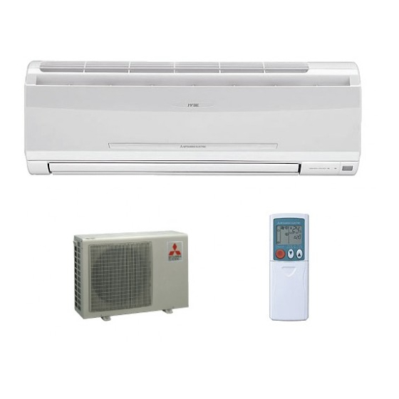
SPLIT-TYPE AIR CONDITIONERS
SERVICE TECHNICAL GUIDE
Models
MSC-GE•VB -
MS-GD•VB -
MS-GE•VB -
MSH-GD•VB -
MSH-GE•VB -
MSZ-GC•VA -
MSZ-HC•VA(B) -
MSZ-CHC•VA -
MSZ-FD•VA(S) -
MSZ-GE•VA -
MSZ-CGE•VA -
MSZ-SF•VA -
MSZ-EF•VEW -
MSZ-EF•VEB -
MSZ-EF•VES -
MLZ-KA•VA -
CONFIDENTIAL
(FOR INTERNAL USE ONLY)
E
E
E
E
E
E
E
E
E
E
E
E
E
E
E
E
Revision G:
• MSZ-EF·VEW -
EF·VES -
added.
Please void OBT17 REVISED EDITION-F.
· MU-GD•VB -
· MU-GE•VB -
· MUH-GD•VB -
· MUH-GE•VB -
· MUZ-GC•VA(H) -
· MUZ-HC•VA(B) -
· MUZ-FD•VA(H)(BH) -
· MUZ-GE•VA(H) -
· MUZ-EF•VE -
· MUZ-EF•VEH -
· MXZ-B•VA -
E
· MXZ-C•VA -
E
CONTENTS
1. MSC/MS/MSH MICROPROCESSOR CONTROL ····· 4
2. MSZ/MLZ MICROPROCESSOR CONTROL ·······11
3. MXZ MICROPROCESSOR CONTROL ··············· 24
,
MSZ-EF·VEB -
E
and
MXZ-C·VA -
have been
E
E
No. OBT17
REVISED EDITION-G
E
E
E
E
E
E
E
E
E
E
,
MSZ-
E
Advertisement
Table of Contents

Related Manuals for Mitsubishi Electric MSC-GE-VB


Summary of Contents for Mitsubishi Electric MSC-GE-VB
- Page 1 Revision G: • MSZ-EF·VEW - MSZ-EF·VEB - MSZ- EF·VES - MXZ-C·VA - have been added. SPLIT-TYPE AIR CONDITIONERS Please void OBT17 REVISED EDITION-F. No. OBT17 REVISED EDITION-G SERVICE TECHNICAL GUIDE Models MSC-GE•VB - MS-GD•VB - · MU-GD•VB - MS-GE•VB - ·...
- Page 2 Revision A: • MSZ-FD·VA - has been added. Revision B: • MS-GD · VB - and MSH-GD · VB - have been added. Revision C: • MSZ-FD50VA - , MSZ-GE·VA - , MSZ-CHC·VA - and MSZ-CGE·VA - have been added. Revision D: •...
-
Page 3: Table Of Contents
2. MSZ/MLZ MICROPROCESSOR CONTROL······································································································ 11 Indoor unit models Outdoor unit models MSZ-GC22/25/35VA MUZ-GC25/35VA(H) MUZ-HC35VA(B) MSZ-HC25VA MSZ-HC35VA(B) MUZ-HC25VA MSZ-CHC25/35VA MUZ-FD25/35VA(H)(BH) MUZ-FD50VABH MSZ-FD25/35/50VA(S) MSZ-GE22/25/35/42/50/60/71VA MUZ-GE25/35/42/50/60/71VA(H) MSZ-CGE22/25/35/42/50VA MUZ-EF25/35/42/50VE MSZ-EF22/25/35/42/50VEW MUZ-EF25/35VEH MSZ-EF22/25/35/42/50VEB MSZ-EF22/25/35/42/50VES MSZ-SF15/20VA MLZ-KA25/35/50VA 2-1. COOL OPERATION ··································································································································· 11 2-2. DRY OPERATION ······································································································································ 12 2-3. -
Page 4: Msc/Ms/Msh Microprocessor Control
MSC/MS/MSH MICROPROCESSOR CONTROL Difference between room 1-1. COOL ( ) OPERATION temperature and set tem- 1. Thermostat control (MSC-GE20/25/35VB) perature during operation Thermostat turns ON or OFF by the difference between room temperature and set temperature Initial temperature difference Thermostat Set temperature Room temperature minus set temperature : 0.3°C or more ················································... - Page 5 1-2. DRY ( ) OPERATION Set temperature and initial room temperature in DRY mode Set temperature is as shown on the right chart. The system for dry operation uses the same refrigerant circuit as the cooling circuit. The compressor and the indoor fan are controlled by the room tem- perature.
- Page 6 2. Indoor fan speed control (1) In AUTO the fan speed Difference between room (MSC-GE20/25/35VB) Indoor fan speed at set speed by FAN SPEED CONTROL button. temperature and set tem- perature during operation Initial temperature difference Fan speed Set temperature minus room temperature: 1.7°C or more ················································· High Set temperature minus room temperature: between 1 and 1.7°C ·································...
- Page 7 4. High pressure protection (MUH-GD80VB, MUH-GE50VB) During heating operation, the outdoor fan and the compressor are controlled by the temperature of indoor coil thermistor for excess rise protection of compressor discharge pressure. • Outdoor fan When the temperature of indoor coil thermistor goes to 55°C or more, the outdoor fan is turned OFF. When the temperature of indoor coil thermistor becomes 52°C or less, the outdoor fan is turned ON.
- Page 8 1-4. INDOOR FAN MOTOR CONTROL (1) Rotational frequency feedback control The indoor fan motor is equipped with a rotational frequency sensor, and outputs signal to the microprocessor to feed- back the rotational frequency. Comparing the current rotational frequency with the target rotational frequency (High, Med., Low), the microprocessor controls SR141 and adjusts fan motor electric current to make the current rotational frequency close to the target rotational frequency.
- Page 9 (2) ECONO COOL ( ) operation (ECONOmical operation) When ECONO COOL button is pressed in COOL mode, set temperature is automatically set 2°C higher. Also the horizontal vane swings in various cycle according to the temperature of indoor heat exchanger. SWING operation makes you feel cooler than set temperature.
- Page 10 1-6. EXPANSION VALVE CONTROL (LEV CONTROL) (MU-GD80VB, MUH-GD80VB) LEV (Expansion valve) is controlled by “Thermostat ON” commands given from the unit. Control range Minimum: 54 pulse, Maximum: 500 pulse Drive speed 30 ~ 90 pulse/second Opening set The setting is always in opening direction. (To close LEV, it is closed to the pulse smaller than the one set finally.
-
Page 11: Msz/Mlz Microprocessor Control
MSZ/MLZ MICROPROCESSOR CONTROL 2-1. COOL ( ) OPERATION 1. Thermostat control (MSZ) Thermostat turns ON or OFF by the difference between room temperature and set temperature. Room temperature minus Room temperature minus Thermostat set temperature (Initial) set temperature (During operation) -1°C or more Less than -1°C -1°C... -
Page 12: Dry Operation
2-2. DRY ( ) OPERATION Set temperature and initial room temperature in dry mode Set temperature is as shown on the right chart. The system for dry operation uses the same refrigerant circuit as the cooling circuit. The compressor and the indoor fan are controlled by the room tem- perature. - Page 13 (2) Cold air prevention control When the compressor is not operating, ( ) if the temperature of room temperature thermistor is less than 19°C, the fan stops. ) if the temperature of room temperature thermistor is 19°C or more and ( ) if the temperature of indoor coil thermistor is less than 0°C, the fan stops.
- Page 14 Time chart of defrosting in HEAT mode (reverse type) <Indoor unit> Horizontal Set position Set position 39 °C ) Horizontal (Temperature of indoor coil thermistor Horizontal vane Indoor fan Very Low (Temperature of indoor coil thermistor > 18 °C) Set speed Set speed seconds <Outdoor unit>...
-
Page 15: Auto Change Over
2-4. AUTO CHANGE OVER ··· AUTO MODE OPERATION (MSZ-GC/FD/GE/CGE/SF/EF, MLZ-KA) Once desired temperature is set, unit operation is switched automatically between COOL and HEAT operation. 1. Mode selection (1) Initial mode At first, indoor unit operates only indoor fan with outdoor unit OFF for 3 minutes to detect present room temperature. Following the conditions below, operation mode is selected. -
Page 16: Drain Pump/Float Sensor Control
<SWING operation> In swing operation of ECONO COOL operation mode, the initial air flow direction is adjusted to “Horizontal”. According to the temperature of indoor coil thermistor at starting of this operation, next downward blow time is decided. After the downward blow has been finished, next horizontal blow time is decided. For initial 10 minutes, the swing operation is performed in table G ~ H for quick cooling. -
Page 17: Inverter System Control
2-8. INVERTER SYSTEM CONTROL 2-8-1. Inverter main power supply circuit MUZ-GC, HC, FD25/35, GE25/35/42/50 CURRENT DIODE TRANSFORMER REACTOR MODULE1 NOISE RESISTOR POWER FILTER SMOOTHING SUPPLY CIRCUIT CAPACITOR RELAY INTELLIGENT COMPRESSOR POWER MODULE SWITCHING POWER DIODE TRANSISTOR MODULE2 BOOSTER CHOPPER CIRCUIT Function of main parts NAME FUNCTION... - Page 18 MUZ-FD50, GE60/71 CURRENT TRANSFORMER REACTOR POWER NOISE RESISTOR FACTOR POWER SMOOTHING FILTER CORRE- SUPPLY CAPACITOR CIRCUIT CTION MODULE RELAY INTELLIGENT COMPRESSOR POWER MODULE Function of main parts NAME FUNCTION INTELLIGENT POWER MODULE It supplies 3-phase AC power to compressor. It stabilizes the DC voltage and supplies it to INTELLIGENT POWER MOD- SMOOTHING CAPACITOR ULE.
- Page 19 Input current waveform without PAM Input current waveform with PAM Due to the time of no electricity; Owing to the increase of energized time; • Power factor gets worse. • Power factor gets better. • Harmonic gets increased. • Harmonic gets suppressed. Release of energy stored in L.
- Page 20 2-8-3. Sine wave control In these air conditioners, compressor equips brushless DC motor which does not have hall element. In short, the motor is sensorless. However, it is necessary to locate the polar direction of rotor in order to drive brushless DC mo- tor effi...
-
Page 21: Operational Frequency Control Of Outdoor Unit
2. Maximum/minimum frequency in each operation mode Operational frequency (Hz) Applied model COOL HEAT Minimum Maximum Minimum Maximum Minimum Maximum MUZ-GC25 MUZ-GC35 MUZ-HC25 MUZ-HC35 MUZ-FD25 MUZ-FD35VA MUZ-FD35VAH/VABH MUZ-FD50 MUZ-GE25 MUZ-GE35 MUZ-GE42 MUZ-GE50 MUZ-GE60 MUZ-GE71 MUZ-EF25 MUZ-EF35 MUZ-EF42 MUZ-EF50 The operation frequency in COOL mode is restricted by the upper limit frequency after 0.5 - 1 hour as shown below for dew prevention. -
Page 22: Expansion Valve Control/Lev Control
MUZ-EF Pre-heat control ON condition (1) Compressor is not operating. (However, pre-heat control is still OFF for 60 minutes after compressor is stopped, regardless of the compressor temperature.) (2) Compressor temperature is monitored hourly, and when the compressor temperature is 20°C or below, pre-heat con- trol is turned ON. -
Page 23: Standby Power Control
(3) Control data (GE60/71) (Other models) Operational frequency of the compressor (Hz) Reference value of target discharge temperature (COOL/HEAT °C) In COOL operation, the two indoor coil Applied model thermistors (one main and one sub) sense MUZ-GC25 54/36 59/46 65/55 70/63 75/70 79/76... -
Page 24: Mxz Microprocessor Control
MXZ MICROPROCESSOR CONTROL 3-1. INVERTER SYSTEM CONTROL 3-1-1. Inverter main power supply circuit MXZ-2B30VA MXZ-2B40VA MXZ-2B52VA CURRENT DIODE TRANSFORMER REACTOR MODULE1 NOISE RESISTOR POWER FILTER SMOOTHING SUPPLY CIRCUIT CAPACITOR RELAY INTELLIGENT COMPRESSOR POWER MODULE SWITCHING POWER DIODE TRANSISTOR MODULE2 BOOSTER CHOPPER CIRCUIT Function of main parts NAME FUNCTION... - Page 25 MXZ-6C120VA REACTOR SMOOTHING CAPACITOR RESISTOR CURRENT DIODE TRANSFORMER NOISE POWER RELAY FILTER SUPPLY CIRCUIT DIODE SWITCHING POWER COMPRESSOR BRIDGE POWER TRANSISTER TRANSISTOR BRIDGE POWER MODULE Function of main parts NAME FUNCTION It absorbs the rush current not to run into the main power supply circuit RESISTOR when the power is turned ON.
- Page 26 Input current waveform without PAM Input current waveform with PAM Due to the time of no electricity; Owing to the increase of energized time; • Power factor gets worse. • Power factor gets better. • Harmonic gets increased. • Harmonic gets suppressed. Input current Input voltage Release of energy stored in L.
- Page 27 MXZ-6C120VA 1. At the start of operation Main power supply circuit is formed when RELAY is turned ON at COMPRESSOR startup. To prevent rush current from running into the circuit when power supply is turned ON, RESISTOR are placed in sub circuit. 2.
-
Page 28: Expansion Valve Control (Lev Control)
3-1-4. Characteristics of sine wave control in case of brushless DC motor ● Although ordinary 3-phase induction motor requires energy to excite the magnetic fi eld of rotor, brushless DC motor does not need it. So, higher effi ciency and torque are provided. ●... - Page 29 • The standard opening is on the straight line, which connects an each standard point in the section where divided into seven according to the operation frequency of compressor as shown in the figure below. (LEV opening is controlled in proportion to the operation frequency.) NOTE: Opening is adjusted at the standard opening according to the indoor unit conditions.
- Page 30 MXZ-3B54VA MXZ-3B68VA MXZ-4B71VA MXZ-3C54VA MXZ-3C68VA MXZ-4C71VA Exclusive LEV Standard opening (pulse) LEV Opening (code) COOL 120 130 136 146 156 160 170 180 190 200 HEAT 248 248 258 266 274 280 286 292 300 306 Difference in capacity Difference in operation number Code 1,2 Code 3,4 Code 5,6 Code 7,8 Code 9,10 Code 11,12 Code 13,14 Code 15 or above COOL HEAT...
- Page 31 MXZ-6C120VA Exclusive LEV Standard opening (pulse) LEV Opening (code) COOL 204 204 204 216 216 216 216 216 216 216 HEAT 130 130 130 140 140 150 150 160 160 170 Difference in capacity Difference in operation number Code 1,2 Code 3,4 Code 5,6 Code 7,8 Code 9,10 Code 11,12 Code 13,14 Code 15 or above COOL -128 -128...
- Page 32 MXZ-3B54VA MXZ-3B68VA MXZ-4B71VA MXZ-3C54VA MXZ-3C68VA MXZ-4C71VA Target discharge temperature (°C) COOL HEAT Operation frequency 4 units 4 units of compressor (Hz) 1 unit 2 units 3 units (MXZ-4B71VA) 1 unit 2 units 3 units (MXZ-4B71VA) (MXZ-4C71VA) (MXZ-4C71VA) Minimum ~ 23 24 ~ 38 39 ~ 54 55 ~ 69...
- Page 33 MXZ-2B40VA MXZ-2B52VA LEV opening correction (pulse) Discharge temperature (°C) COOL HEAT More than Target discharge temperature + 10 Target discharge temperature + 10 to Target discharge temperature + 5 Target discharge temperature + 5 to Target discharge temperature + 2 Target discharge temperature + 2 to Target discharge temperature - 2 Target discharge temperature - 2 to Target discharge temperature - 5 Target discharge temperature - 5 to Target discharge temperature - 10...
-
Page 34: Operational Frequency Range
(2) Separate correction (COOL, DRY) (Correction by the separate superheat) Correct the LEV separately by temperature difference "∆RT" between main/sub indoor coil thermistor. LEV opening correction (pulse) ∆RT MXZ-2B/3B/4B71/3C/4C71 MXZ-4B80/5B/4C80/5C/6C ∆RT ∆RT< 4 ∆RT< 2 3-3. OPERATIONAL FREQUENCY RANGE MXZ-2B30VA Number of operating Capacity COOL(Hz) - Page 35 MXZ-3B68VA MXZ-4B71VA MXZ-3C68VA MXZ-4C71VA COOL (Hz) HEAT (Hz) Number of operating Capacity code DRY (Hz) unit Min. Max. Min. Max. Defrost 8~10 11~13 14~16 MXZ-4B80VA MXZ-5B100VA MXZ-4C80VA MXZ-5C100VA COOL (Hz) HEAT (Hz) Number of operating Capacity code DRY (Hz) Max. unit Min.
-
Page 36: Heat Defrosting Control
3-4. HEAT DEFROSTING CONTROL (1) Starting conditions of defrosting When the following conditions a) ~ c) are satisfied, the defrosting starts. a) The defrost thermistor reads -2.3°C or less. b) The cumulative operation time of the compressor has reached any of the set values (31, 35, 45, 55, 65, 75, 85, 95, 105, 115, 150 minutes). -
Page 37: Outdoor Fan Control
3-7. OUTDOOR FAN CONTROL MXZ-3B54VA MXZ-3B68VA MXZ-4B71VA MXZ-4B80VA MXZ-5B100VA MXZ-3C54VA MXZ-3C68VA MXZ-4C71VA MXZ-4C80VA MXZ-5C100VA MXZ-6C120VA COOL Fan speed changes so that the condensing temperature stays within the target range. Revolution per minutes (rpm) MXZ-3B54VA MXZ-3B68VA MXZ-4B80VA MXZ-2B30VA Fan speed MXZ-4B71VA MXZ-5B100VA MXZ-2B40VA MXZ-6C120VA... -
Page 38: Pre-Heat Control
3-8. PRE-HEAT CONTROL The compressor is energized even while it is not operating. This is to generate heat at the winding to improve the compressor's start-up condition. Power Compressor Defrost thermistor 21°C 30 minutes 30 minutes 30 minutes 30 minutes 30 minutes 30 minutes minutes... -
Page 39: Heat Operation
3-11. HEAT OPERATION 1. Thermostat control Thermostat turns ON or OFF by difference between room temperature and set temperature. Room temperature minus Room temperature minus Thermostat set temperature (Initial) set temperature (During operation) less than 1°C 1°C or more 0.7°C 1°C 2. - Page 40 HEAD OFFICE: TOKYO BLDG.,2-7-3, MARUNOUCHI, CHIYODA-KU, TOKYO 100-8310, JAPAN © Copyright 2007 MITSUBISHI ELECTRIC CO.,LTD Distributed in Nov. 2010. No. OBT17 REVISED EDITION-G Distributed in Jan. 2010. No. OBT17 REVISED EDITION-F 5 Distributed in Oct. 2009. No. OBT17 REVISED EDITION-E 6 Distributed in Dec.