Table of Contents
Advertisement
Quick Links
Download this manual
See also:
Owner's Manual
Advertisement
Table of Contents

Related Manuals for Motorola MW810


Summary of Contents for Motorola MW810
- Page 1 MW810 Mobile Workstation Model F5208, Release 1.2 Installation Manual...
- Page 3 Motorola, except for the normal non-exclusive, royalty free license to use that arises by operation of law in the sale of a product.
- Page 4 C) should the Product or its parts become, or in Motorola's opinion be likely to become, the subject of a claim of infringement of a United States patent, that such purchaser will permit Motorola, at its option and expense, either...
- Page 5 Private DataTAC is a registered trademark of Motorola Inc. Microsoft, Windows and the Windows logo are registered trademarks of Microsoft Corporation. The Bluetooth trademarks are owned by their proprietor and used by Motorola, Inc. under license in the U.S. and other countries.
-
Page 6: References
6802982C95 MW810 Mobile Workstation Series, Maintenance Programming Software Own- ers Guide (included on the FIELD SUPPORT KIT Software CD - FVN5613) For the latest version of this guide and other MW810 Mobile Workstation manuals go to: www.motorola.com/enterprisemobility/manuals Internet Web Sites Motorola Web site: http://www.motorola.com/MW810... -
Page 7: Using This Manual
Using this Manual Who Should Use this Manual This manual is intended for trained service technicians, radio engineers, and technical operation support staff who install the 810 Mobile Workstation (MW810 Model ) in a vehicle. F5208 What is in this Manual This manual describes the tools and equipment, planning requirements, and product inspections necessary for a smooth installation of the MW810. - Page 8 This Page Intentionally Left Blank...
-
Page 9: Table Of Contents
Introduction ..................1 How to identify the workstation release number ........... 2 Installation.................... 3 Unpacking ......................3 Preparing to Install the MW810 Mobile Workstation Inside the Vehicle ..... 3 Tools ......................... 3 Planning........................4 MW810 Mobile Workstation Mounting Location ........... 4 Air Bag Considerations .................... - Page 10 Power (PWR) Connection ..................35 AUX Port Connection .................... 35 Display Connection ....................38 Connection of MW810 Mobile Workstation CPU Box to a Standard Display..41 Connection of MW810 Mobile Workstation Auxiliary Port to Vehicle Wiring..42 Connection of ALPR Cameras ................43 Table 8 details the pin layout of the ALPR Connector........
-
Page 11: Introduction
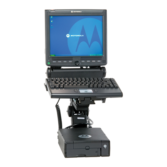
Box, Display and Keyboard and can be mounted in dual airbag-equipped vehicles. Using custom-designed cable adapters, the CPU can be connected to a 12.1” or 8.4” MW810 Mobile Workstation display or 3rd-party LCD, CRT or Flat Screen display. Each component can also be used as a stand-alone product interfacing to 3rd party equipment. -
Page 12: How To Identify The Workstation Release Number
How to identify the workstation release number This manual relates to MW810 Mobile Workstation releases 1.1 and 1.2. The release number reflects the type of hardware and software installed inside the MW810 Mobile Workstation. When receiving the MW810 Mobile Workstation, the release information is included with the documentation attached to the shipping package. -
Page 13: Installation
This section describes the tools and equipment, planning requirements, and product inspections necessary for a smooth installation of the MW810. Proper planning will help to ensure that the installation is completed without difficulty and that no damage occurs to the units or the vehicle. -
Page 14: Planning
• The workstation parts are properly ventilated. • Place the MW810 Mobile Workstation so that it can be easily removed for servicing. • Do not mount the MW810 Mobile Workstation and route its cables where they can be kicked by the driver’s or other passenger’s foot. -
Page 15: Air Bag Considerations
• Select a location that permits routing the RF antenna cable as directly as possible. • If you are mounting the MW810 Mobile Workstation on a plastic dashboard, you must first reinforce the dashboard; otherwise the weight of the display may crack or break the dashboard. - Page 16 MW810 Mobile Workstation Vehicle Installation Manual Figure 1 Air Bag Deployment Zones - Crown Victoria Figure 2 Air Bag Deployment Zones - Caprice Figure 3 Air Bag Deployment Zones - Lumina...
-
Page 17: Environmental Considerations
The display and CPU Box are designed to operate properly in an ambient temperature range of -22°F to 158°F (-30°C to +70°C). The MW810 Mobile Workstation CPU must be installed in an area with adequate air flow to allow for proper ventilation. Installers must install the CPU in an unobstructed location in order to allow proper air flow (see Figure 4). - Page 18 VERY IMPORTANT: Connect the GROUND lead of any device that is connected to the MW810, i.e., radio or any other equipment, to one common chassis point, via a ring lug, as...
- Page 19 Insert a grommet with a 5 mm (0.2 inch) inner diameter into the access hole to avoid damage to the cable (see Figure 6). To MW810 Mobile Workstation Figure 6. Cable Routing into Engine Compartment Take special care not to damage any existing vehicle wires.
-
Page 20: Cable Routing
MW810 Mobile Workstation Vehicle Installation Manual 5. Install the supplied ring lugs onto the stripped end of the black lead, and onto the fuse holder at the end of the red lead (see Figure 7). For 13.8 VDC +/- 20% System, use 15A Fuse For 27.6 VDC +/- 20% System, use 10A Fuse... -
Page 21: 12.1" Display
Installation • Do not locate cables where they can be kicked by the driver or passengers or where they can interfere with operation of the driver’s foot pedals. • When routing the cable, refrain from creating sharp bends or kinks. •... - Page 22 MW810 Mobile Workstation Vehicle Installation Manual Gamber Johnson Mount 11.5” 3.34” Allow Service Loop 2.61” Power Cable CPU to Display Signal Cable 7.4” USB Keyboard Cable 9.6” 1.92” USB Port USB Port 10.7” Display Power USB Port CPU to Display...
- Page 23 Connection to Standard Personal Computer The laptop to MW810, 12.1” Display Signal Cable (optional DVI, P.N FKN8454 or RGB, P.N FKN8449 cable) enables you to interface the MW810, 12.1” Display to any laptop or personal computer. For cable connection, refer to Figure 9.
-
Page 24: 8.4" Display
MW810 Mobile Workstation Vehicle Installation Manual 8.4” Display The 8.4” Display can be attached to a mount by four M4 screws. 9.1" 3.93" W 1.7" 7.1” 3.93" Figure 10 8.4” Display Size The CPU box to Display cable can be ordered in two basic configurations with various lengths: 1) Right side driving countries (driver's seat on left-hand side). - Page 25 Four M4, 10 Screws Adjustment Knob Figure 11 MW810 8.4” Display - Free-standing Pedestal Mount This section describes the tools and equipment, planning requirements, and product inspections necessary for a smooth installation of the 8.4" Display. Proper planning will help to ensure that the installation is completed without difficulty and that no damage occurs to the units or the vehicle.
- Page 26 MW810 Mobile Workstation Vehicle Installation Manual Step 2. If screws and nuts are used for anchoring the mount, mark the hole locations using the base of the mount and drill four 5.5 mm holes into the dashboard. Step 3. If self-tapping screws are used for anchoring the mount, attach the mount to the desired location and drive the screws into the dashboard.
- Page 27 Installation In-dash DIN Mount The In-dash DIN Mount is a rectangular (2” high x 7” wide) mount that can be adapted to most vehicles produced today that contain a standard ‘Single DIN’ opening. During installation, the display can be adjusted to provide optimal accessibility using the following pivot and mounting adjustments (see Figure 13): •...
- Page 28 MW810 Mobile Workstation Vehicle Installation Manual To mount the DIN sleeve inside the radio slot, perform the following steps: The DIN mount can only be adjusted during installation and may require reinstallation before the final position is determined. No end- user adjustment is available.
- Page 29 Installation To Assumable and Install the Display DIN Mount, perform the following steps (see Figure 15): Step 1. Position the left-hand side and right-hand side Arm Brackets inside the DIN Sleeve. Use the holds on the arms to determine the distance of the display from the dash, and fasten the arms using four nuts to inner studs.
- Page 30 MW810 Mobile Workstation Vehicle Installation Manual Step 5. Plug the connector of the display signal cable and use the three screws to secure the connector to the display. Step 6. ote that cables are available with right-side or left-side display exit for right-side or left-side driver seat position.
- Page 31 Swivel Plate. Connection to Standard Personal Computer The Laptop to MW810, 8.4” Display Signal Cable (optional DVI, p/n FKN8547 or RGB, p/n FKN8546 cable) enables you to interface the MW810, 8.4” Display to any laptop or personal computer.
-
Page 32: Cpu Box
The limiting factor for the length of the display signal cable is 5 meter (16.4 feet). Whenever one of the MW810 Mobile Workstation receptacles is not in use, it is recommended to leave the receptacle plug. Use the supplied rubber plugs to cover the unused receptacles (see Figure 18). - Page 33 Note SIM Installation SIM card is a small smart card that fits inside the MW810. The SIM card holds identification information about the MW810 Mobile Workstation WWAN radio including the network activation.
- Page 34 MW810 Mobile Workstation Vehicle Installation Manual Step 4. Slide-in to lock the SIM drawer. SIM Drawer Eject Button SIM Drawer Figure 20 CPU Box - SIM Card Installation The CPU Box can be mounted at any place in the passenger compartment that provides adequate ventilation (see Figure 4).
- Page 35 For GPS Dead Reckoning installation, refer to “Appendix A Installation, Configuration and Calibration of GPS Dead Reckoning” on page 49 Motorola recommends the use of the CPU Box mount/trunnion. Failure to do so may result in hard drive damage due to vibration.
-
Page 36: Keyboard
MW810 Mobile Workstation Vehicle Installation Manual Keyboard The keyboard tray may be placed anywhere in the vehicle. Please ensure that all safety guidelines and air-bag deployment requirements are met. When a mounting tray is used, the keyboard is provided with a quick release holder to allow operation of the keyboard when out of the holder. -
Page 37: Interface To The Mw810 Mobile Workstation Cpu Box
With the mechanical installation complete, hook up the optional antennas and other peripheral devices to the CPU Box and Display. The MW810 Mobile Workstation offers multiple expansion board options each with a different rear panels, so you can add more ports for external modems, video cameras, or other vehicle peripherals as needed (see Figure 23). - Page 38 MW810 Mobile Workstation Vehicle Installation Manual Figure 24 shows an optional connection layout of the MW810. Note that any USB 1.1 or USB 2.0, RS-232 or Bluetooth devices may be used. Ensure that the cables are properly routed to prevent damage to the cables and any operator hazards.
-
Page 39: Wwan Antenna Connection
3. Ensure that the installation surface is grounded by connecting grounding straps between the surface and the vehicle chassis. 4. Ensure that the antenna cable can be easily routed to the MW810. Route the antenna cable as far away as possible from any vehicle electronic control units and associated wiring. -
Page 40: Wlan Radio Antenna Connection
MW810 Mobile Workstation Vehicle Installation Manual Mini-UHF Connection To ensure a secure connection of an antenna cable's mini-UHF plug to a MW810 mini-UHF jack, their interlocking features must be properly engaged. If they are not properly engaged, the plug will come loose. Using a tool (pliers or wrench) will not overcome a poor engagement, and is not recommended. -
Page 41: Gps Connection
Installation GPS Connection The MW810 Mobile Workstation may be supplied with an optional internal module of Global Positioning System (GPS). Connect the cable connector of the GPS antenna to the GPS connector at the rear panel of the CPU Box, on one side, and to the connector of an active GPS antenna on the other side. - Page 42 MW810 Mobile Workstation Vehicle Installation Manual Table 1 details the pin layout of the USB connection Table 1 USB Connection - Pin Layout Pin No. Signal USB- USB+...
-
Page 43: Serial Connection
Installation Serial Connection ® The RS-232 ports are standard IBM PC DB-9 male connectors. These ports can be used to connect an external radio modem, or any other serial device. The devices you connect to the Serial ports usually do not require installing a driver. However, if the serial device requires a software, please use the original driver provided with the device. -
Page 44: Audio Line In Connection
Table 4 10/100 Base-T Ethernet Connection - Pin Layout Pin No. Signal Audio Line In Connection The MW810 Mobile Workstation is equipped with a Audio In connector to which an external microphone can be connected. Audio Line In IN and VREF... -
Page 45: Audio Line Out Connection
The MW810 Mobile Workstation is equipped with two Motorola DC power cables and fuses, one for the CPU Box and the other for the display. To connect power to the MW810 Mobile Workstation units, refer to “Electrical Guidelines” on page 7. - Page 46 MW810 Mobile Workstation Vehicle Installation Manual Step 2. Connect pin 5 to the vehicle ground. Pin 26 Pin1 Pin 5 to vehicle ground Pin 8 to vehicle ignition switch Figure 26 AUX Connection - Ignition Sense Pin-outs Table 5 AUX Connection - Pin Layout Pin No.
- Page 47 Installation Pin No. Signal Description Ground 5V Power output. Maximum 1 Amps. Output is automatically disconnected when CPU Box temperature is exceeds operating range 5V Power output. Maximum 1 Amps. Output is automatically disconnected when CPU Box temperature is exceeds operating range...
-
Page 48: Display Connection
RGB (DISPLAY1 connection) and digital DVI (DISPLAY2 connection). Use only Motorola original integrated molded cables for connection to the MW810 Mobile Workstation display or to 3rd-party LCD, CRT or Flat Screen displays. The CPU Box graphic controller supports resolutions up to 1280x1024. - Page 49 Installation Table 6 DISPLAY 1 Connection - Pin Layout Pin No. Signal HSYNC LINE_OUT_L# LINE_OUT_R# MIC2- Table 7 details the pin layout of the connection DISPLAY 2 Table 7 DISPLAY 2 Connection - Pin Layout Signal TDC2 TDC2# TDC1# TDC1 TDC0 TDC0# HSYNC...
- Page 50 MW810 Mobile Workstation Vehicle Installation Manual Table 7 DISPLAY 2 Connection - Pin Layout VSYNC DDC_CLK0 DDC_DATA0 SECONDERY_MDR MDR2_SPARE1 SEC_DISP_ON_BTN TLC# USB7- USB7+ V_5SUS BLUE GREEN HPDET_5V SEC_DISPLAY_LID# MIC3- MIC3+...
-
Page 51: Connection Of Mw810 Mobile Workstation Cpu Box To A Standard Display
LINE_OUT_R# Connection of MW810 Mobile Workstation CPU Box to a Standard Display The MW810 Mobile Workstation CPU Box to Standard Display Cable (optional DVI, P.N FKN8544 or RGB, P.N FKN8450 cable) enables you to interface the MW810 Mobile Workstation CPU Box to a standard DVI or RGB display. For cable connection, refer to Figure 17. -
Page 52: Connection Of Mw810 Mobile Workstation Auxiliary Port To Vehicle Wiring
MW810 Mobile Workstation Vehicle Installation Manual Connection of MW810 Mobile Workstation Auxiliary Port to Vehicle Wiring The Auxiliary cable with terminal block (FKN8533) enables you to interface the MW810 Mobile Workstation CPU Box to the Vehicle Wiring. For terminal connections, refer to “AUX Connection - Pin Layout”... -
Page 53: Connection Of Alpr Cameras
ALPR Splitter Cable MW810 Mobile Workstation CPU Box DISPLAY 2 ALPR DISPLAY 1 SERIAL 1 W-WAN Mic In Mic In Audio Out Audio Out W-LAN MAIN MAIN Figure 29 Connection of MW810 Mobile Workstation Auxiliary Port to Vehicle Wiring... - Page 54 MW810 Mobile Workstation Vehicle Installation Manual Table 8 details the pin layout of the Connector ALPR Table 8 ALPR Connector Pin layout...
-
Page 55: Turning On The Mw810
Using the Power Button and Ignition Key to Start the MW810 Mobile Workstation The MW810 Mobile Workstation can be turned ON by the following method: 1. Turn ON the ignition switch. 2. Press the Power button of the CPU Box or Display to turn ON the MW810. -
Page 56: Turning Off The Mw810
The MW810 Mobile Workstation can be turned OFF by either one of the following methods: 1. Turn OFF the ignition key. Turn OFF the MW810 Mobile Workstation via the OS. Note that in order to turn ON the MW810, the ignition key should be turned to OFF position, and switched back to ON. -
Page 57: Storage
Installation Storage Important Note: Maximum storage period in shipping package is six months. To refresh storage, assemble the workstation and run Disk Defragmenter (Go to: Start->Programs- >Accessories->System Tools->Disk Defragmenter) - Page 58 MW810 Mobile Workstation Vehicle Installation Manual This Page Intentionally Left Blank...
-
Page 59: Installation, Configuration And Calibration Of Gps Dead Reckoning
CPU Box can not track turns if the gyro is not set properly. When the MW810 is ordered with a GPS Dead Reckoning option, the gyro wired to the U- blox GPS module needs to be situated in accordance to the installation position of the CPU Box. -
Page 60: Vertical Installation - Front Panel Facing Up
MW810 Vehicle Mobile Workstation Installation Manual Vertical Installation - front panel facing up CPU Box Front Step 1. Remove the six screws that secure the top cover of the CPU Box. Gyro Unit Step 2. Orient and mount the Gyro unit as shown in the picture. -
Page 61: Vertical Installation - Back Panel Facing Up
Appendix A Installation, Configuration and Calibration of GPS Dead Reckoning Vertical Installation - back panel facing up Step 1. Remove the six screws that secure the top cover of the CPU Box. Gyro Unit Step 2. Orient and mount the Gyro unit as shown in the picture. -
Page 62: Vertical Installation - Cpu Back Panel Facing Sideways
MW810 Vehicle Mobile Workstation Installation Manual Vertical Installation - CPU back panel facing sideways Step 1. Remove the six screws that secure the top cover of the CPU Box. Gyro Unit Step 2. Orient and mount the Gyro unit as shown in the picture. -
Page 63: Horizontal Installation Of Cpu Box
Appendix A Installation, Configuration and Calibration of GPS Dead Reckoning Horizontal Installation of CPU Box Step 2. Orient the Gyro unit as shown the picture. Step 1. Remove the six screws that secure the top cover of the CPU Box. Gyro Unit Step 2. -
Page 64: Unsupported Cpu Box Positions
MW810 Vehicle Mobile Workstation Installation Manual Unsupported CPU Box positions IMPORTANT: Do not install the CPU Box in the following orientations when using the GPS Dead Reckoning option in the MW8100. Figure 34 GPS Dead Reckoning - Unsupported CPU Box positions Vehicle’s floor... -
Page 65: Vehicle Wire Connections
Appendix A Installation, Configuration and Calibration of GPS Dead Reckoning Vehicle wire connections The GPS Dead Reckoning navigation system connects to the vehicle's reverse signal wires (or reverse light) and the speed signals. This connection signals the navigation system when the vehicle is traveling forward or in reverse See “GPS Dead Reckoning - Vehicle wire connections”... -
Page 66: U-Blox U-Center Configuration
To configure the u-blox GPS receiver, perform the following steps: Step 1. Download the U-Center application from: http://www.u-blox.com/products/ u_center.html. Step 2. Install the U-Center application on the MW810. Step 3. Click START > Programs > U-Blox Products > Tools > U-Center Application to run the U-Center application. - Page 67 Appendix A Installation, Configuration and Calibration of GPS Dead Reckoning Step 7. From the left window pane, select UBX > CFG (Config) > PRT (Ports) Step 8. Set “Protocol in” and “Protocol out” to “0+1 - UBX+NMEA”. Step 9. From the left window pane, select UBX > CFG (Config) > MSG (Messages) Step 10.
- Page 68 MW810 Mobile Workstation Vehicle Installation Manual Step 13. Select the first NAV-EKFSTATUS message from the “Message” drop list and click button to save. Step 14. From the left side window, select UBX > CFG (Config) > CFG (Configuration) Step 15. Check "Save current configuration" and "Devices" options and click the button to save.
- Page 69 Appendix A Installation, Configuration and Calibration of GPS Dead Reckoning Step 18. Verify the wiring connection: a. From the left side window, select UBX > NAV >EKFSTATUS. b. Verify that the Direction change when in reverse gear c. Verify that the gyro reading shows readings around 33000 d.
-
Page 70: Automatic Calibration
MW810 Mobile Workstation Vehicle Installation Manual Automatic Calibration Basics Automatic Calibration takes place continuously & transparently during periods of good GPS reception while driving around. Benefits • Accuracy improves over time of operation • Fully compensates effects from aging (aging effects of gyroscope) •... -
Page 71: Automatic Calibration - Testing Environment
Appendix A Installation, Configuration and Calibration of GPS Dead Reckoning - Gyroscope is calibrated while driving straight (offset) with making turns (scaling factor) Automatic Calibration – Testing Environment Driving recommendation if high accuracy is required very quickly, e.g. for product testing and benchmarking: The following driving directions are recommended to achieve an efficient calibration so dead reckoning yields high accuracy after a short period of time. - Page 72 MW810 Mobile Workstation Vehicle Installation Manual This Page Intentionally Left Blank...
-
Page 73: Appendix B -Accessories
3.5 m (11.5 ft.) Laptop to MW810 DVI Display 8.4" RGB Display Cables FKN8455 3.5 m (11.5 ft.) MW810 8.4" Display to CPU RGB Cable, right side driver FKN8456 5 m (16.4 ft.) MW810 8.4" Display to CPU, RGB Cable, right side... - Page 74 MW810 Mobile Workstation Vehicle Installation Manual Extender Cables FKN8201 USB keyboard extender cable, 1.8 m (6 ft.) ALPR Cables FKN8584 CPU 36 Pin to 50 Pin ALPR 5 m (16.4 ft.) DVI FKN8577 CABLE SPLITTER ALPR 50 Pin Keyboards FLN3673...
- Page 75 5 m (16.4 ft.) MW810 CPU to standard DVI display FKN8460 MODS Adapter Cable FKN8532 Y Cable for MW810 (for indoor use only. Not for vehicle installation) FPN1655 Power supply with Y Cable FKN8544 3.5m (11.5ft.) 50 pin Cable, CPU to Standard Display, DVI...
- Page 76 MW810 Mobile Workstation Vehicle Installation Manual This Page Intentionally Left Blank...
-
Page 77: Acronyms
Acronyms Ampere Positive (Acknowledgment) ALPR Automatic License Plate Recognition Auxiliary Central Processing Unit CVBS Composite Video Blanking and Sync Direct Current DRAM Dynamic Random Access Memory Digital Video Interface Federal Communications Commission GigaHertz GPIO General Purpose Input/Output GPRS General Packet Radio Service Global Positioning System Input/Output Local Area Network... - Page 78 MW810 Mobile Workstation Vehicle Installation Manual Near Infrared Transmission (also cd/m2, a measure of luminance) NTSC National Television System Committee Operating System Power Amplifier Phase Alternation Line Personal Computer PCMCIA Personal Computer Memory Card International Association Peripheral Component Interconnect Portable Radio Modem...
- Page 80 For Europe, the Middle East and Africa, call +420 533 336 123 MOTOROLA and the Stylized M Logo are registered in the U.S. Patent and Trademark Office. All other product or service names are the property of their respective owners.