Sony CFD-G30 Service Manual
Hide thumbs
Also See for CFD-G30:
- Operating instructions manual (72 pages) ,
- Operating instructions manual (36 pages) ,
- Limited warranty (1 page)
Table of Contents
Advertisement
Quick Links
SERVICE MANUAL
Ver 1.0 2000. 02
AUDIO POWER SPECIFICATIONS
POWER OUTPUT AND TOTAL HARMONIC DIST ORTION
With 3.2 Ω loads, both c hannels dr iven fr om 150 – 10,000 Hz; r ated 2.5 W
per c hannel-minim um RMS po wer, with no mor e than 10 % total har monic
distortion in AC oper ation.
Woofer with 4-ohm loads, dr iven a t 50 -150 Hz; r ated 9.5 W minim um RMS
power, with no mor e 10 % total har monic distor tion in AC oper ation.
Other Specifications
CD player section
System
Compact disc digital audio system
Laser diode properties
Material: GaAlAs
Wavelength:780 nm
Emission duration : Continuous
Laser output : Less than 44.6 µW
(This output is the v alue measur ed a t a distance of
about 200 mm fr om the objecti ve lens surf ace on
the optical pick-up block with 7 mm aperture.)
Spindle speed
200 r/min (r pm) to 500 r/min (r pm) (CLV)
Number of channels
2
Frequenc y response
20 – 20,000 Hz + 0.5/-1.5 dB
Wow and f lutter
Below measur able limit
Radio section
Frequenc y range
FM
:
AM
:
Aerials
FM
:
AM
:
Cassette-corder section
Recording system
4 -track 2 channel stereo
Fast winding time
Approx. 110 sec . with Son y cassette C-60
Frequenc y response
TYPE I (normal) : 70 – 13,000 Hz
General
Full r ang e : 10 cm (4 in.) dia., 3.2 Ω, cone type (2)
Speak ers
Woofer : 8 cm (3
Inputs
LINE IN (ster eo minijac k) : Senseti vity 436 mV
Outputs
Headphones jack (stereo minijack)
F or 16 – 68 Ω impedance headphones
Power output (e xcluding US model)
Full range :
4 W + 4 W (at 3.2 Ω, 10 % har monic distor tion in
DC operation)
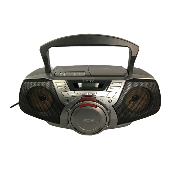
CFD-G30/G50
PHOTO : CFD-G50
CD
Section
Tape deck
Section
SPECIFICATIONS
87.6 – 108 MHz
530 – 1,710 kHz
Telescopic antenna
Built-in ferrite bar aerial
in.) dia., 4 Ω, cone type (1)
1
/
4
Canadian Model
Model Name Using Similar Mechanism
CD Mechanism Type
Optical Pick-up Name
Model Name Using Similar Mechanism
Tape Transport Mechanism Type
Woofer :
12W (at 3.2 Ω, 10 % har monic distor tion in
DC operation)
Power r equir ements
F or CD r adio cassette-cor der :
120V AC, 60 Hz
12V DC, 8 size D (R 20) batteries
F or r emote contor ol (CFD-G50 onl y):
3V DC, 2 size AA (R6) batter ies
Power consumption
AC 30W
Battery life
F or CD r adio cassette-cor der:
FM recording
Son y R20P : approx. 8 h
Son y alkaline LR20 : approx. 18 h
Tape playback
Son y R20P : approx. 1.5 h
Son y alkaline LR20 : approx. 6 h
CD playback
Son y R20P : approx. 1 h
Son y alkaline LR20 : approx. 4 h
Approx. 500 × 206 × 328 mm (w/h/d)
Dimensions
× 8
(19
3
/
4
parts)
Mass
Approx. 7 kg (15 lb . 7 oz) (inc l. ba tter ies)
Supplied accessories
AC power cor d (1)
Remote control (1) (CFD-G50 only)
Design and specif ications ar e subject to c hang e without notice .
CD RADIO CASSETTE-CORDER
US Model
E Model
CFD-G30/G50
CFD-G50
CFD-V17
KSM-213CDM
KSS-213C
CFD-V17
MF-V10-117
× 13 inches) (incl. projecting
1
/
8
Advertisement
Table of Contents

Related Manuals for Sony CFD-G30


Summary of Contents for Sony CFD-G30
-
Page 1: Specifications
CFD-G30/G50 SERVICE MANUAL US Model E Model Ver 1.0 2000. 02 CFD-G30/G50 Canadian Model CFD-G50 PHOTO : CFD-G50 Model Name Using Similar Mechanism CFD-V17 CD Mechanism Type KSM-213CDM Section Optical Pick-up Name KSS-213C Tape deck Model Name Using Similar Mechanism... -
Page 2: Table Of Contents
LES COMPOSANTS IDENTIFÉS PAR UNE MARQUE ! SUR LES DIAGRAMMES SCHÉMATIQUES ET LA LISTE DES PIÈCES SONT CRITIQUES POUR LA SÉCURITÉ DE FONCTIONNEMENT. NE REMPLACER CES COMPOSANTS QUE PAR DES PIÈSES SONY DONT LES NUMÉROS SONT DONNÉS DANS CE MANUEL OU DANS LES SUPPÉMENTS PUBLIÉS PAR SONY. -
Page 3: Service Notes
SECTION 1 SERVICE NOTES Laser component in this product is capable NOTES ON HANDLING THE OPTICAL PICK-UP of emitting radiation exceeding the limit for BLOCK OR BASE UNIT Class 1. The laser diode in the optical pick-up block may suffer electrostatic breakdown because of the potential difference generated by the charged electrostatic load, etc., on clothing and the human body. -
Page 4: General
SECTION 2 GENERAL LOCATION AND FUNCTION OF CONTROLS ,wf,wg,wh CD Z PUSH OPEN/CLOSE button Tape operation buttons CD LID button CD u button N button VOLUME + button m button VOLUME − button M button CD x button x, Z button Speaker button LINE jack... -
Page 5: Disassembly
SECTION 3 DISASSEMBLY • The equipment can be removed using the following procedure. Cabinet (upper) assy Power, Batt, Tuner, batt com board Front cabinet assy Control-1, Head phone board Main, LIine in, Lcd board CD board, Optical pick-up section, Mechanism deck Note : Follow the disassembly procedure in the numerical order given. -
Page 6: Control-1, Head Phone Board
3-2. CONTROL-1, HEAD PHONE BOARD 5 Two connectors 3 Screw +PWH 2.6 × 10 4 HEAD PHONE board 1 Ten screws +BVTP 2.6 × 8 2 CONTROL-1 board 3-3. CABINET (UPPER) ASSY 2 Open the cassette the holder assy by pressing STOP/EJECT button. -
Page 7: Power, Batt, Tuner, Batt Com Board
3-4. POWER, BATT, TUNER, BATT COM BOARD !∞ Connector 8 Power board !¢ Screw 1 Screw +WH 3 × 8 +BVTP 3 × 12 6 Two screws +BVTP 3 × 16 !§ BATT COM board 5 Two screws +BVTP 3 × 10 !º... -
Page 8: Cd Board, Optical Pick-Up Section
3-6. CD BOARD, OPTICAL PICK-UP SECTION, MECHANISM DECK 1 Remove solder 2 Screw +P 2 × 6 3 CD board 4 Three screws +PWH 2.6 × 10 5 Two screws +PWH 2.6 × 10 7 Three screws +BVTP 3 × 10 6 Optical pick-up section 8 Mechanism deck section —... -
Page 9: Adjustment
SECTION 4 ADJUSTMENTS 0dB = 0.775V 4-1. MECHANICAL ADJUSTMENT 4-2. ELECTRICAL ADJUSTMENT PRECAUTION TAPE RECODER SECTION Clean the following parts with a denatured-alchool-moistened swab: Standard output level record/playback head pinch roller Output HP OUT erase head rubber belts 32 Ω capstans Load impedance Demagnetize the record/playback head with a head... - Page 10 • Repeat the procedures in each adjustment several times for the 0 dB = 1 µV TUNER SECTION maximum level meter indication. • The frequency coverage and tracking adjustments should be • Switch Location finally done by the trimmer capacitors. VOLUME : MAX MEGA BASS...
-
Page 11: Diagram
CFD-G30/G50 SECTION 5 DIAGRAMS 5-1. CIRCUIT BOARDS LOCATION CD SECTION Focus Bias Check This check is to be done when the optical block replaced. BATT board POWER board Check Procedure: 1. Connect the oscilloscope to test point TP (VC) and TP (RF) on MAIN board. - Page 12 CFD-G30/G50 5-2. BLOCK DIAGRAMS – TUNER/CD SECTION – TUNER BOARD ANT1 RADIO 6V TELESCOPIC FRONT-END ANTENNA IF AMP,DET,FM MPX QUAD VCC1 VCC2 FM TRACKING FM RF I MIX OUT FM IF RADIO 6V L-CH MAIN FM/AM SECTION MUTE BUFFER R-CH F-COVER.
-
Page 13: Main Section
CFD-G30/G50 – MAIN SECTION – WAVEFORM Note on Printed Wiring Board: IC2 w; • X : parts extracted from the component side. • Y : parts extracted from the conductor side. • b : Pattern from the side which enables seeing. -
Page 14: Schematic Diagram - Cd Section
CFD-G30/G50 5-3. SCHEMATIC DIAGRAM – CD SECTION – • Refer to page 17 for Note on Schematic Diagrams. • Refer to page 17 for Waveforms. • Refer to page 45, 46 for IC Block Diagrams. (Page 35) The components identified by... -
Page 15: Printed Wiring Board - Cd Section
CFD-G30/G50 5-4. PRINTED WIRING BOARD – CD SECTION – • Refer to page 12 for Circuit Boards Location. • Refer to page 17 for Note on Printed Wiring Board. • Semiconductor Location Ref. No. Location IC701 IC702 IC703 Q701 Q702... -
Page 16: Schematic Diagram - Cassette Deck Section
CFD-G30/G50 • Refer to page 17 for Note on Schematic Diagrams. • Refer to page 17 for Waveforms. • Refer to page 46 for IC Block Diagrams. 5-5. SCHEMATIC DIAGRAM – CASSETTE DECK SECTION – — 23 — — 24 —... -
Page 17: Printed Wiring Board - Cassette Deck Section
CFD-G30/G50 5-6. PRINTED WIRING BOARD – CASSETTE DECK SECTION – • Refer to page 12 for Circuit Boards Location. • Refer to page 17 for Note on Printed Wiring Board. — 25 — — 26 —... -
Page 18: Schematic Diagram - Tuner Section
CFD-G30/G50 • Refer to page 17 for Note on Schematic Diagrams. • Refer to page 17 for Waveforms. • Refer to page 47 for IC Block Diagrams. 5-7. SCHEMATIC DIAGRAM – TUNER SECTION – 0.01 100P — 27 — — 28 —... -
Page 19: Printed Wiring Board - Tuner Section
CFD-G30/G50 5-8. PRINTED WIRING BOARD – TUNER SECTION – • Refer to page 12 for Circuit Boards Location. • Refer to page 17 for Note on Printed Wiring Board. — 29 — — 30 —... -
Page 20: Printed Wiring Board - Main Section
CFD-G30/G50 • Refer to page 12 for Circuit Boards Location. • Refer to page 17 for Note on Printed Wiring Board. 5-9. PRINTED WIRING BOARD – MAIN SECTION – • Semiconductor Location Ref. No. Location (Page 42) D321 D322 D325... -
Page 21: Schematic Diagram - Main Section (1/2)
CFD-G30/G50 5-10. SCHEMATIC DIAGRAM – MAIN SECTION (1/2) – • Refer to page 17 for Note on Schematic Diagrams. • Refer to page 48 for IC Block Diagrams. LINE 6.8k 2.2k (Page 40) — 33 — — 34 —... -
Page 22: Schematic Diagram - Main Section (2/2)
CFD-G30/G50 • Refer to page 17 for Note on Schematic Diagrams. • Refer to page 12 for Circuit Boards Location. 5-11. SCHEMATIC DIAGRAM – MAIN SECTION (2/2) – C521 0.01 C573 C574 0.01 0.01 D512 — 35 — — 36 —... -
Page 23: Control Section
CFD-G30/G50 5-12. PRINTED WIRING BOARD AND SCHEMATIC DIAGRAM – CONTROL SECTION – • Refer to page 12 for Circuit Boards Location. • Refer to page 17 for Note on Printed Wiring Board. • Refer to page 17 for Note on Schematic Diagrams. -
Page 24: Schematic Diagram - Power Section
CFD-G30/G50 • Refer to page 17 for Note on Schematic Diagrams. 5-13. SCHEMATIC DIAGRAM – POWER SECTION – *1: F902 4A: G30:E4/G50:E4 6.3A: EXCEPT G30:E4/G50:E4 223mA 219mA 277mA 420mA 0.63A The components identified by mark ! or dotted line with mark ! are critical for safety. -
Page 25: Printed Wiring Board - Power Section
CFD-G30/G50 5-14. PRINTED WIRING BOARD – POWER SECTION – • Refer to page 17 for Note on Printed Wiring Board. — 41 — — 42 —... -
Page 26: Ic Pin Function Description
CFD-G30/G50 5-16. IC PIN FUNCTION DESCRIPTION • IC501 CXP83620-019Q (SYSTEM CONTROL) Pin No. Pin Name Description Pin No. Pin Name Description C-SCOR CD SCOR input CD function output RMC input terminal — Power supply MUTE Mute — External 150 kHz oscillator is connected to this terminal f tex divided-by-16 frequency output terminal —... -
Page 27: Ic Block Diagrams
5-17. IC BLOCK DIAGRAMS IC701 CXA2550M IC703 BA5974FP MUTE INTERFACE LEVEL SHIFT THERMAL SHUTDOWN INTERFACE INTERFACE — 45 —... - Page 28 IC702 CXD2587Q ERROR ASYMMETRY DIGITAL DIGITAL CORRECTOR CORRECTION LRCK OPERATIONAL AMPLIFIER PCMD INTERFACE DEMODULATOR ANALOG SWITCH CONVERTER EMPH XVDD CLOCK XTSL GENERATOR XTAI TIMING TES1 LOGIC XTAO TEST XVSS SERVO DSP PWM GENERATOR AVDD1 FRDR FOCUS FOCUS PWM AOUT1 SERVO GENERATOR FFDR AIN1...
- Page 29 IC1 TA2149N BUFF DECODE BUFF DIVIDE 1/1 or 1/16 BUFF LEVEL BUFF ST/MO FM/AM FMRF AMIF AMIF MUTE IC2 LC72137 REFERENCE PHASE DETECTOR 16 PD DIVIDER CHARGE PUMP XOUT 17 AIN UNLOCK SWALLOW COUNTER FMIN 1/16, 1/17 4bits DETECTOR 18 AOUT 12bits PROGRAMMABLE AMIN DIVIDER...
- Page 30 IC321 LC75342 VREF TEST LOUT ROUT LBASS2 RBASS2 LBASS1 RBASS1 LTRE RTRE LSELO RSELO — 48 —...
-
Page 31: Exploded Views
SECTION 6 EXPLODED VIEWS NOTE: • -XX, -X mean standardized parts, so they may • The mechanical parts with no reference number The components identified by mark 0 or have some differences from the original one. in the exploded views are not supplied. dotted line with mark 0 are critical for safety. -
Page 32: Rear Cabinet Section
6-2. REAR CABINET SECTION ANT1 T901 not supplied not supplied Ref. No. Part No. Description Remarks Ref. No. Part No. Description Remarks X-3378-766-1 HOLDER ASSY, CASSETTE (G50:US,CND,MX) * 63 A-3322-558-A TUNER BOARD, COMPLETE (G30:E4/G50:E4) X-3378-776-1 HOLDER ASSY, CASSETTE (G30/G50:E4,E92) 3-041-991-01 TERMINAL, ANTENNA 3-041-965-01 LID(CD) (G50:US,CND,MX) 3-389-436-41 LID,BATTERY CASE (G50:US,CND,MX) 3-041-965-11 LID(CD) (G30/G50:E4,E92) -
Page 33: Upper Cabinet Section
6-3. UPPER CABINET SECTION S801 LCD651 supplied not supplied Ref. No. Part No. Description Remarks Ref. No. Part No. Description Remarks 3-047-468-01 DAMPER 3-923-736-01 COVER, CD 3-041-964-01 CABINET (UPPER) (G50:US,CND,MX) 3-910-095-21 RUBBER, VIBRATION PROOF 3-041-964-11 CABINET (UPPER) (G30/G50:E4,E92) 3-910-095-31 RUBBER, VIBRATION PROOF 3-032-041-11 BUTTON (REC) (G50:US,CND,MX) 3-921-725-01 SCREW (2.6X10), +PWH 3-032-041-21 BUTTON (REC) (G30/G50:E4,E92) -
Page 34: Mechanism Deck Section (1) (Mf-V10-117)
6-4. MECHANISM DECK SECTION (1) (MF-V10-117) HRP301 HE301 Ref. No. Part No. Description Remarks Ref. No. Part No. Description Remarks 3-933-010-01 SPRING (S/P), TORSION * 162 3-008-587-01 SLIDER (STOP) 3-933-025-01 SPRING (P), TORSION * 163 3-008-591-01 SLIDER (PAUSE) 3-933-026-01 LEVER (P) 3-933-004-01 CLAW, REEL 3-933-024-01 ROLLER, PINCH * 165... -
Page 35: Mechanism Deck Section (2) (Mf-V10-117)
6-5. MECHANISM DECK SECTION (2) (MF-V10-117) S602 S601 M601 Ref. No. Part No. Description Remarks Ref. No. Part No. Description Remarks 3-933-029-01 LEVER, ERASING PREVENTION 3-932-993-01 CHASSIS, OUTSERT 3-933-182-01 SPRING, CASSETTE 3-343-358-01 RING, RETAINING 3-932-995-01 GEAR (MID) 3-933-005-01 SPRING (CAM), COMPRESSION X-3371-667-1 CLUTCH ASSY 3-939-383-02 SPRING, COMPRESSION 3-932-997-01 GEAR (CAM) -
Page 36: Optica Pick-Up Section (Ksm-213Cdm)
6-6. OPTICAL PICK-UP SECTION (KSM-213CDM) not supplied ( * : including M702) * : M702 M701 Ref. No. Part No. Description Remarks Ref. No. Part No. Description Remarks 0 254 2-626-908-01 SHAFT, SLED 8-848-483-05 OPTICAL PICK-UP KSS-213C 2-627-003-02 GEAR (B)(RP) X-2626-202-1 CHASSIS ASSY (MB)(RP),MOTOR(SPINDLE) 2-626-907-01 GEAR (A)(S) (INCLUDING M702) -
Page 37: Electrical Parts List
BATT COM BATT SECTION 7 ELECTRICAL PARTS LIST NOTE: • Due to standardization, replacements in the • CAPACITORS: • SEMICONDUCTORS parts list may be different from the parts uF: µF In each case, u: µ, for example: specified in the diagrams or the components •... - Page 38 Ref. No. Part No. Description Remarks Ref. No. Part No. Description Remarks JC706 1-216-296-91 SHORT JC768 1-216-296-91 SHORT JC707 1-216-296-91 SHORT JC769 1-216-296-91 SHORT JC708 1-216-296-91 SHORT JC770 1-216-296-91 SHORT JC709 1-216-296-91 SHORT JC771 1-216-296-91 SHORT JC710 1-216-296-91 SHORT JC772 1-216-295-91 SHORT JC711 1-216-296-91 SHORT...
- Page 39 CONTROL-1 CONTROL-2 CONTROL-3 HEAD PHONE Ref. No. Part No. Description Remarks Ref. No. Part No. Description Remarks R762 1-216-246-00 RES-CHIP 100K 1/8W < SWITCH > R774 1-216-055-00 METAL CHIP 1.8K 1/10W R775 1-216-049-91 RES-CHIP 1/10W S601 1-762-798-11 SWITCH, KEYBOARD (MEGA BASS) R776 1-216-065-91 RES-CHIP 4.7K...
- Page 40 LINE IN MAIN Ref. No. Part No. Description Remarks Ref. No. Part No. Description Remarks 1-676-525-11 LCD BOARD C126 1-127-869-21 CERAMIC 2700PF C127 1-127-888-21 CERAMIC 0.1uF ********** C128 1-127-888-21 CERAMIC 0.1uF 3-041-989-01 HOLDER (LCD) C129 1-126-960-11 ELECT 20.00% 50V C130 1-126-961-11 ELECT 2.2uF 20.00% 50V...
- Page 41 MAIN Ref. No. Part No. Description Remarks Ref. No. Part No. Description Remarks C513 1-128-802-21 CERAMIC 27PF < IC > C514 1-128-802-21 CERAMIC 27PF C516 1-126-961-11 ELECT 2.2uF 20.00% 50V IC321 8-759-669-03 IC LC75342 C517 1-126-963-11 ELECT 4.7uF 20.00% 50V IC322 8-759-634-51 IC M5218AP C518...
- Page 42 MAIN Ref. No. Part No. Description Remarks Ref. No. Part No. Description Remarks R126 1-247-863-91 CARBON 1/4W R517 1-249-417-11 CARBON 1/4W F R127 1-249-429-11 CARBON 1/4W R521 1-249-417-11 CARBON 1/4W F R128 1-247-895-91 CARBON 470K 1/4W R522 1-249-417-11 CARBON 1/4W F R129 1-249-413-11 CARBON 1/4W F...
- Page 43 POWER Ref. No. Part No. Description Remarks Ref. No. Part No. Description Remarks 1-676-475-11 POWER BOARD C304 1-104-664-11 ELECT 47uF 20.00% 10V C305 1-137-431-11 MYLAR 560PF 5.00% 50V ************* C306 1-163-021-91 CERAMIC CHIP 0.01uF 10.00% 50V 1-533-233-11 HOLDER,FUSE C307 1-163-011-11 CERAMIC CHIP 0.0015uF 10% <...
- Page 44 TUNER Ref. No. Part No. Description Remarks Ref. No. Part No. Description Remarks A-3322-456-A TUNER BOARD, COMPLETE 1-163-251-11 CERAMIC CHIP 100PF 5.00% 50V (G30:US,E92/G50:US,CND,E92,MX) 1-163-181-00 CERAMIC CHIP 100PF 5.00% 50V 1-163-251-11 CERAMIC CHIP 100PF 5.00% 50V ********************** A-3322-558-A TUNER BOARD, COMPLETE (G30:E4/G50:E4) 1-163-021-91 CERAMIC CHIP 0.01uF 10.00% 50V...
- Page 45 TUNER VOL SEL Ref. No. Part No. Description Remarks Ref. No. Part No. Description Remarks JC44 1-216-295-91 SHORT MISCELLANEOUS ************** < COIL > 1-792-040-11 WIRE, PARALLEL (6 CORE) 1-416-533-11 COIL, AIR-CORE 1-452-899-11 MAGNET 1-416-509-11 COIL, AIR-CORE 1-501-883-21 ANTENNA, TELESCOPIC 1-754-117-11 ANTENNA, FERRITE-ROD (MW) 1-692-960-11 SWITCH, PUSH (1 KEY) 1-411-234-21 COIL, AM OSC 1-792-241-11 WIRE, PARALLEL (17 CORE)
- Page 46 CFD-G30/G50 Sony Corporation 2000B1637-1 Personal Audio Division Company 9-927-676-11 Printed in Japan ©2000.2 — 64 — Published by General Engineering Dept.