Table of Contents
Advertisement
HP MSM466-R Access Point Installation
Guide
Abstract
This document describes how to install and initially configure the -MSM466-R Dual Radio Outdoor 802.1 1n Access Point
(hereafter referred to as the AP). This document applies to these MSM466-R models: J9715A (AM), J9716A (WW), J9717A
(JP), J9718A (IL). Professional wireless and electrical equipment experience is required. For controlled mode, see also MSM7xx
Controllers Configuration Guide. For autonomous mode, see also MSM3xx / MSM4xx APs Configuration Guide.
HP Part Number: 5998-3783
Published: March 2013
Edition: 1
Advertisement
Table of Contents

Related Manuals for HP MSM466-R


Summary of Contents for HP MSM466-R
- Page 1 Guide Abstract This document describes how to install and initially configure the -MSM466-R Dual Radio Outdoor 802.1 1n Access Point (hereafter referred to as the AP). This document applies to these MSM466-R models: J9715A (AM), J9716A (WW), J9717A (JP), J9718A (IL). Professional wireless and electrical equipment experience is required. For controlled mode, see also MSM7xx Controllers Configuration Guide.
- Page 2 © Copyright 2013 Hewlett-Packard Development Company, L.P. The information contained herein is subject to change without notice. The only warranties for HP products and services are set forth in the express warranty statements accompanying such products and services. Nothing herein should be construed as constituting an additional warranty. HP shall not be liable for technical or editorial errors or omissions contained herein.
-
Page 3: Table Of Contents
Testing the wireless network.....................19 Before performing additional configuration................19 4 Working with antennas................20 Available antennas.........................20 5 Support and other resources..............21 Online Documentation......................21 Contacting HP........................21 HP Websites..........................21 Typographic conventions......................21 A Regulatory information................22 Notice for U.S.A........................22 Notice for Canada.........................23 Notice for the European Community..................23 Supported external antennas....................24... -
Page 4: Preparing For Installation
1 Preparing for installation Package contents One AP One weatherproof RJ-45 Ethernet connector One pole mounting/wall mounting bracket Bracket bolts (x2), lock washers (x2), flat washers (x4) Wall anchors (x4) and screws (x4) Pole clamps (x2) for a 5 cm (2 inch) diameter pole Documentation Additional equipment needed In addition to the items supplied with the AP, protection equipment will be required according to... -
Page 5: Important Information To Read Before Installing
Failure to do so may result in personal injury, fire, equipment damage, or a voided warranty. The HP hardware warranty provides no protection against damage caused by static discharge or a lightning strike. Lightning arresters (not supplied) are available from HP (J8996A). -
Page 6: Powering The Ap
The AP can be powered by: A 10/100/1000 PoE-enabled (802.3af or 802.3at) switch. PoE-enabled switches are available from HP. HP 1-Port 802.3af Gig PoE Power Injector (J9407B). HP 1-Port 802.3at Gig PoE Power Injector (JD054A). CAUTION: If the AP will be powered by a user-supplied PoE power injector, use only a gigabit-compatible power injector. -
Page 7: Installing
Identify a suitable installation location. The AP is IP67 and NEMA 4X rated, providing protection against water intrusion and salt fog damage. Local electrical and building codes and regional regulations will dictate many aspects of your installation. HP recommends that you test transmission and reception at the proposed location before installing. -
Page 8: Installing Cabling
Hold the screw nut (5) vertically, with the open threads facing up, and drop the body (6) into it, with the RJ-45 connector opening facing up. Hold the clamp ring (3) vertically below the screw nut/body items and screw the body (6) into the threads on the clamp ring (3). -
Page 9: Mounting The Ap
Mounting the AP Pole installation IMPORTANT: The AP and antennas can be mounted on a pole with a diameter of 32 to 57 mm (1.25 to 2.25 inches). The pole must be capable of supporting the AP and antennas at the maximum anticipated wind loading. - Page 10 Figure 5 Mounting Bracket Attached 1. Bracket bolt (x2) 4. Bracket 7. Screw hole (x4) 2. Lock washer (x2) 5. Flat washer (x2) 8. Pole clamp slot (x4) 3. Flat washer (x2) 6. Bracket post (x2) 9. Pole cut out Locate the two bracket bolts (1), the two lock washers (2), and the four flat washers (3, 5).
- Page 11 (5) at the desired position and then fully tighten the pole clamp screw to anchor the AP against the pole (5). Attach the second pole clamp (4) in the same manner as the first, also firmly tightening it. Figure 6 AP mounted on pole 1.
-
Page 12: Wall Installation
Wall installation Refer to Figure 7. Hold the mounting bracket as a drilling template against the wall at the desired position with the two bracket bolt holes (4) facing the left and right sides. Using the four screw holes on the bracket (1), mark four holes for the screws (wall anchors). Figure 7 Mounting bracket 1. - Page 13 Refer to Figure 8. Locate the two bracket bolts (1), the two lock washers (2), and the four flat washers (3, 5). Onto each bracket bolt (1), thread a lock washer (2) followed by a flat washer (3). Push both washers against the bracket bolt (1) head. Figure 8 Mounting Bracket Attached (wall not shown) 1.
- Page 14 Verify that the bracket (4) is now connected to the AP and the wall as illustrated in Figures 8 and 9, respectively. Figure 9 AP mounted on wall 1. Bracket post 2. Bracket 3. Wall 10. Rotate the AP up or down to the desired position and then firmly tighten both bracket bolts to 50 kgf-cm (43.4 lbf-in).
-
Page 15: Connecting The Ap
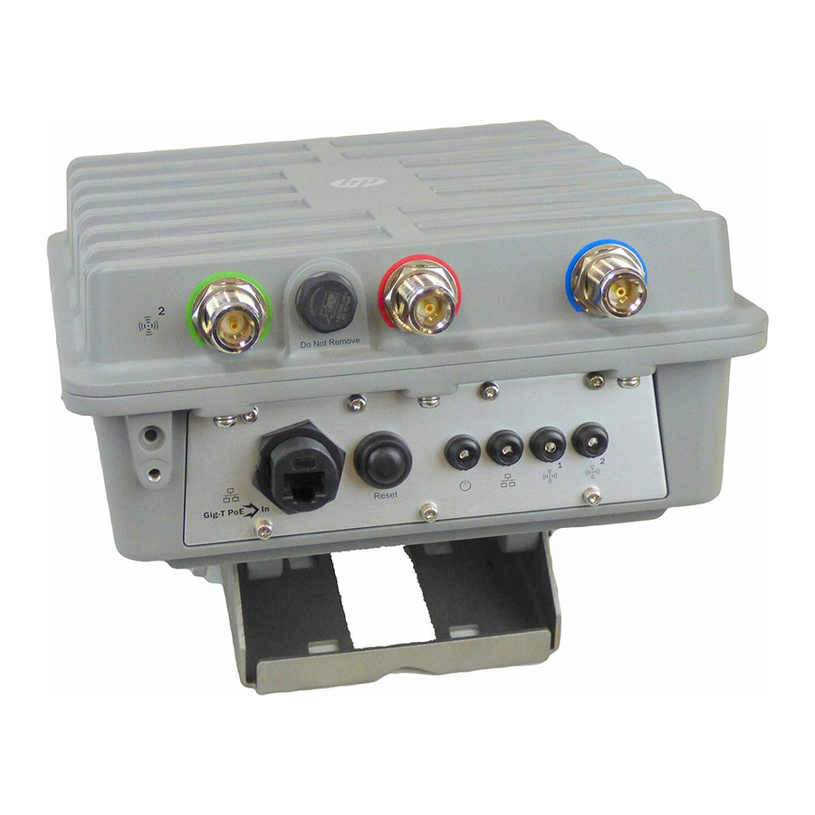
Install antennas including antenna connector lightning arresters as described in the respective antenna guide available online (search by antenna part number). An HP Lightning Arrester (J8996A) Guide is also available online. - Page 16 Attaching the Ethernet cable Refer to Figure 1 1. Connect the Ethernet cable to the Ethernet connector (see “AP key components (bottom end)” (page 4)). Figure 1 1 Drip loop 1. Pole 2. 15 cm (6 inches) 3. 25 cm (10 inches) Create a drip loop in the Ethernet cable below the AP.
-
Page 17: Initially Configuring (Autonomous Mode)
3 Initially configuring (autonomous mode) This procedure describes how to switch a factory-default AP from controlled mode (the default) to autonomous mode and then perform its initial configuration and establish a wireless connection through the AP to the Internet. Understanding operating modes The AP can operate in one of two modes: controlled (the default) or autonomous. -
Page 18: Logging In
“Important information to read before installing” (page At the password prompt HP recommends that you change the default password and select Save. Passwords must be at least six characters long and include four different characters. If you forget this password, you will have to reset the AP to factory defaults to regain access. -
Page 19: Assigning An Ip Address To The Ap
IP address and a DNS address automatically as described in your operating system documentation. By default, the AP creates a wireless network named HP in the 5GHz band for 802.1 1n and 802.1 1a users. Connect your computer to this wireless network, specifying the pre-shared key you set earlier in Step 2 of “Configuring basic wireless protection”... -
Page 20: Working With Antennas
Depending on the country of use, the antenna selected, and your radio settings, it may be mandatory to reduce the radio transmission power level to maintain regulatory compliance. For specific power limits for your country, consult the HP MSM466-R External Antenna RF Power-level Setting Guide available from www.hp.com/support/manuals... -
Page 21: Support And Other Resources
5 Support and other resources Online Documentation You can download documentation from the HP Support Website at: www.hp.com/support/manuals. Search by product number or name. Contacting HP For worldwide technical support information, see the HP support Website: www.hp.com/ networking/support Before contacting HP, collect the following information:... -
Page 22: A Regulatory Information
A Regulatory information Notice for U.S.A. Manufacturer's FCC Declaration of Conformity statement Manufacturer: Hewlett-Packard Company 3000 Hanover Street Palo Alto, CA 94304- 1 185 USA For questions regarding this declaration, contact the Product Regulations Manager at the above address. FCC Class B statement This FCC Class B device complies with Part 15 of the FCC rules. -
Page 23: Notice For Canada
R&TTE Directive 1999/5/EC. Compliance with these directives implies conformity to harmonized European standards (European Norms) that are listed on the EU Declaration of Conformity that has been issued by HP for this device. See also “Waste Electrical and Electronic Equipment (WEEE) statements” (page 26) Countries of operation &... -
Page 24: Supported External Antennas
2.4 GHz operation This device may be operated outdoors or indoors in all EU and EFTA countries using the 2.4 GHz band (Channels 1 - 13), except where noted below. In France, this device may use the entire 2400 - 2483.5 MHz band (Channels 1 through 13) for indoor applications. -
Page 25: Notice For Taiwan
Notice for Taiwan DGT LPD (Low Power Device) statement Korean notices Class B equipment Turkish recycling notice Türkiye Cumhuriyeti: EEE Yönetmeliğine Uygundur Vietnamese Information Technology and Communications compliance marking Notice for Taiwan... -
Page 26: B Recycle Statements
B Recycle statements Waste Electrical and Electronic Equipment (WEEE) statements English recycling notice Disposal of waste equipment by users in private household in the European Union This symbol means do not dispose of your product with your other household waste. Instead, you should protect human health and the environment by handing over your waste equipment to a designated collection point for the recycling of waste electrical and electronic equipment. -
Page 27: Estonian Recycling Notice
Estonian recycling notice Äravisatavate seadmete likvideerimine Euroopa Liidu eramajapidamistes See märk näitab, et seadet ei tohi visata olmeprügi hulka. Inimeste tervise ja keskkonna säästmise nimel tuleb äravisatav toode tuua elektriliste ja elektrooniliste seadmete käitlemisega egelevasse kogumispunkti. Küsimuste korral pöörduge kohaliku prügikäitlusettevõtte poole. Finnish recycling notice Kotitalousjätteiden hävittäminen Euroopan unionin alueella Tämä... -
Page 28: Italian Recycling Notice
Italian recycling notice Smaltimento di apparecchiature usate da parte di utenti privati nell'Unione Europea Questo simbolo avvisa di non smaltire il prodotto con i normali rifi uti domestici. Rispettare la salute umana e l'ambiente conferendo l'apparecchiatura dismessa a un centro di raccolta designato per il riciclo di apparecchiature elettroniche ed elettriche. -
Page 29: Romanian Recycling Notice
Romanian recycling notice Casarea echipamentului uzat de către utilizatorii casnici din Uniunea Europeană Acest simbol înseamnă să nu se arunce produsul cu alte deşeuri menajere. În schimb, trebuie să protejaţi sănătatea umană şi mediul predând echipamentul uzat la un punct de colectare desemnat pentru reciclarea echipamentelor electrice şi electronice uzate.