Sony WM-FS555 Service Manual
Radio cassette player
Hide thumbs
Also See for WM-FS555:
- Service manual (22 pages) ,
- Operating instructions (2 pages) ,
- Manual (2 pages)
Table of Contents
Advertisement
WM-FS555/FS556
SERVICE MANUAL
Ver 1.2 2003.02
Sony Corporation
9-873-595-03
Personal Audio Company
2003B0200-1
Pubulished by Sony Engineering Corporation
© 2003.02
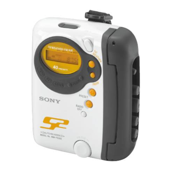
Photo : WM-FS555
Model Name Using Similar Mechanism
MD Mechanism Type
SPECIFICATIONS
• Frequency
TV: 2-13 ch
WEATHER: 1-7ch
FM: 87.5-108 MHz
AM: 530-1710 kHz (North, Central and South America)
531-1602 kHz (Other counries)
• Power requirements
1.5 V DC battery size AA (R6) × 1
• Dimensions
Approx. 102.3 × 117.5 × 47.3 mm (4
including projecting parts and controls
• Mass
Approx. 219 g (7.8 oz) (main unit only)
• Supplied accessories
Stereo headphones or earphones (1)
Hand strap with belt clip (1)
Design and specifications are subject to change witout notice.
Canadian Model
NEW
MF-WMFS555-114
1
/
× 4
/
× 1
7
/
inches)
3
8
4
8
RADIO CASSETTE PLAYER
US Model
WM-FS555/FS556
AEP Model
E Model
WM-FS555
Advertisement
Table of Contents

Related Manuals for Sony WM-FS555


Summary of Contents for Sony WM-FS555
- Page 1 • Supplied accessories Stereo headphones or earphones (1) Hand strap with belt clip (1) Design and specifications are subject to change witout notice. RADIO CASSETTE PLAYER Sony Corporation 9-873-595-03 Personal Audio Company 2003B0200-1 Pubulished by Sony Engineering Corporation © 2003.02...
-
Page 2: Table Of Contents
WM-FS555/FS556 TABLE OF CONTENTS Flexible Circuit Board Repairing Specifications ................1 • Keep the temperature of the soldering iron around 270°C during 1. GENERAL repairing............... 2 • Do not touch the soldering iron on the same conductor of the circuit board (within 3 times). -
Page 3: Disassembly
WM-FS555/FS556 SECTION 2 DISASSEMBLY The equipment can be removed using the following procedure. Mechanism deck Belt, Capstan/reel motor (M601), Chassis, H/P board Main board Magnetic head (playback) (HP901) Note : Follow the disassembly procedure in the numerical order given. 2-1. CHASSIS, H/P BOARD 2 Two screws (B1.7 ×... -
Page 4: Mechanism Deck
WM-FS555/FS556 2-3. MECHANISM DECK Chassis 1 Claws Mechanism deck 2-4. BELT, CAPSTAN/REEL MOTOR (M601), MAGNETIC HEAD (PLAYBACK) (HP901) 2 Two screws (M1.4) 4 Two screws (M1.4) 3 Capstan/reel motor Mechanism deck (M601) • How to apply the belt Capstan/reel motor... -
Page 5: Adjustments
WM-FS555/FS556 SECTION 3 ADJUSTMENTS 3-1. MECHANICAL ADJUSTMENTS 3-2. ELECTRICAL ADJUSTMENTS PRECAUTION PRECAUTION 1. Clean the following parts with a denatured-alcohol-moistened • Supplied voltage : 1.5 V. swab : • Switch and control position (MENU display) playback head pinch roller MEGA BASS : OFF... - Page 6 WM-FS555/FS556 TUNER SECTION 0 dB = 1µV AM TRACKING ADJUSTMENT Adjust for a maximum reading on level meter. AM Section 620kHz <621kHz> BAND : AM 1,400kHz <1,395kHz> AM RF signal Put the lead-wire generator antenna close to the set. FM FREQUENCY COVERAGE CONFIRMATION...
- Page 7 WM-FS555/FS556 Adjustment Location : [MAIN BOARD] (SIDE A) L2 : FM Tracking Adjustment L7 : TV Tracking Adjustment CT1 : AM Tracking Adjustment L5 : AM Frequency Coverage Adjustment L4: AM Tracking Adjustment...
-
Page 8: Diagrams
WM-FS555/FS556 SECTION 4 DIAGRAMS 4-1. EXPLANATION OF IC TERMINALS IC701 TC9329FA-CFX1740 (SYSTEM CONTROL) Pin No. Pin name Description 1 – 4 COMI-4 LCD common drive. 5 – 19 S1-15 LCD segment drive. 20 – 22 K01-03 Key output. 23 – 26 K1-4 Key input. -
Page 9: Block Diagrams
WM-FS555/FS556 4-2. BLOCK DIAGRAMS EXCEPT US MODEL POWER AMP PRE AMP HP901 IC301 (2/2) US MODEL IC301 (1/2) PLAY BACK RV301 HEAD VOLUME PRE AMP R-CH PRE OUTA J301 PW INA OUTA HEADPHONE PW NFA Q101 AVSL PRE NFA Q305... -
Page 10: Printed Wiring Boards - Main Section
WM-FS555/FS556 4-3. PRINTED WIRING BOARDS – MAIN SECTION – Semiconductor M601 Location CAPSTAN/REEL MOTOR Ref. No. Location (SIDE A) MAIN BOARD (SIDE B) MAIN BOARD HOLD . D401 D402 D701 HP901 IC301 PLAYBACK IC601 IC701 HEAD IC703 L-CH Q101 Q102... -
Page 11: Schematic Diagram - Main Section (1/2)
WM-FS555/FS556 4-4. SCHEMATIC DIAGRAM − MAIN SECTION (1/2) − Refer to page 13 for Notes. Refer to page 13 for Waveforms. Refer to page 13 for IC Block Diagrams. -
Page 12: Schematic Diagram - Main Section (2/2)
WM-FS555/FS556 4-5. SCHEMATIC DIAGRAM − MAIN SECTION (2/2) − Refer to page 13 for Notes. Refer to page 14 for IC Block Diagrams. -
Page 13: Ic Block Diagrams
WM-FS555/FS556 Note on Schematic Diagram: MAIN SECTION Waveforms • All capacitors are in µF unless otherwise noted. pF: µµF 50 WV or less are not indicated except for electrolytics and tantalums. • All resistors are in Ω and W or less unless otherwise specified. - Page 14 WM-FS555/FS556 IC301 TA2160FN (EL) RF & REF PW C AGC DET PW A PW B PRE A PRE B BST SW IC601 MM1279XVBE MOTIVE CONTROL DRIVER CIRCUIT MOTIVE SOFT MOTIVE LOGIC SWITCH /OSC INVERTER BIAS VREF SPEED CURRENT REFERENCE CONTROL...
-
Page 15: Exploded Views
WM-FS555/FS556 SECTION 5 EXPLODED VIEWS NOTE : • Hardware (# mark) list and accessories and packing • -XX, -X mean standardized parts, so they materials are given in the last of this parts list. may have some difference from the original one. -
Page 16: Cabinet Section
WM-FS555/FS556 5-2. CABINET SECTION MF-WMFS555-114 LCD701 Ref. No. Part No. Description Remark Ref. No. Part No. Description Remark 3-386-371-21 PACKING, HP JACK 3-227-297-01 BUTTON (PLAY) 3-221-321-11 KNOB (VOL) 3-227-300-01 BUTTON (REW) 3-012-927-01 RING, O 3-235-970-01 CHASSIS X-3381-679-1 CABINET (REAR) SUB ASSY (FS555:US, 3-318-203-32 SCREW (B1.7), TAPPING... -
Page 17: Mechanism Deck Section
WM-FS555/FS556 Ver 1.1 2003.01 5-3. MECHANISM SECTION (MF-WMFS555-114) supplied supplied supplied supplied supplied HP901 M601 supplied Ref. No. Part No. Description Remark Ref. No. Part No. Description Remark X-3369-749-8 PINCH LEVER (N) ASSY 3-920-990-21 SPRING (UD), COMPRESSION X-3372-619-3 WHEEL ASSY (NP), CAPSTAN 3-704-197-71 SCREW (M1.4) -
Page 18: Electrical Parts List
WM-FS555/FS556 Ver 1.2 2003.02 SECTION 6 MAIN ELECTRICAL PARTS LIST NOTE : • Due to standardization, replacements in the • Items marked “ * ”are not stocked since they When indicating parts by reference num- parts list may be different from the parts are seldom required for routine service. - Page 19 WM-FS555/FS556 MAIN Ref. No. Part No. Description Remark Ref. No. Part No. Description Remark C312 1-135-149-21 TANTALUM CHIP 2.2uF D402 8-719-404-50 DIODE MA111-TX D701 8-719-049-09 DIODE 1SS367-T3SONY C316 1-115-156-11 CERAMIC CHIP C322 1-115-416-11 CERAMIC CHIP 0.001uF <FERRITE BEAD> C323 1-115-156-11 CERAMIC CHIP C324 1-104-847-11 TANTAL.
- Page 20 WM-FS555/FS556 MAIN Ref. No. Part No. Description Remark Ref. No. Part No. Description Remark <RESISTOR> R301 1-216-845-11 METAL CHIP 100K 1/16W R302 1-216-845-11 METAL CHIP 100K 1/16W 1-216-821-11 METAL CHIP 1/16W R303 1-216-845-11 METAL CHIP 100K 1/16W 1-216-833-11 METAL CHIP...
- Page 21 WM-FS555/FS556 Ver 1.2 2003.02 MAIN Ref. No. Part No. Description Remark S707 1-771-053-12 SWITCH, KEY BOARD (SET) S708 1-771-053-12 SWITCH, KEY BOARD (TUNING+) S711 1-771-053-12 SWITCH, KEY BOARD (MENU) <TRANSFORMER> T401 1-437-569-11 TRANSFORMER, DC-DC CONVERTER <THERMISTOR> TH601 1-810-794-11 THERMISTOR, POSITIVE) <VIBLATOR>...
-
Page 22: Revision History
Also, clicking the version at the upper right on the revised page allows you to jump to the next revised page. Ver. Date Description of Revision 2002.02 2003.01 Part No. correction of exploded views (Ref. No. 127). (SPM-02058) 2003.02 6US model and 2CND model addition for WM-FS555. (ENG-03006)