Table of Contents
Advertisement
REW
PLAY
POWER
EJECT/ STOP
STANDBY
/
CH(TRACKING)
AV 2 IN VDEO
L(MONO)-AUDIO-R
DV-NC55S/H
EJECT/
OPERATE
STOP
REW
PLAY/X2
/
C H
REC
LINE 3 IN VDEO
L(MONO)-AUDIO-R
DV-NC60H
1. IMPORTANT SERVICE NOTES ........................................................................................................ 2
2. FEATURES ........................................................................................................................................ 3
3. SPECIFICATIONS ............................................................................................................................. 3
4. PART NAMES .................................................................................................................................... 5
5. MAINTENANCE CHECK ITEMS AND EXECUTION TIME ............................................................... 9
6. DISASSEMBLY METHOD ............................................................................................................... 10
7. OPERATION OF PICKUP ............................................................................................................... 14
8. ADJUSTMENT, REPLACEMENT AND ASSEMBLY OF MECHANICAL UNITS ............................ 15
9. ELECTRICAL ADJUSTMENT .......................................................................................................... 38
10. TEST MODE .................................................................................................................................... 41
11. TROUBLESHOOTING ..................................................................................................................... 44
12. IC FUNCTION LIST ......................................................................................................................... 58
13. BLOCK DIAGRAMS ......................................................................................................................... 82
14. SCHEMATIC DIAGRAMS ................................................................................................................ 92
15. PRINTED WIRING BOARD ASSEMBLIES ................................................................................... 114
16. REPLACEMENT PARTS LIST ...................................................................................................... 137
17. PACKING OF THE SET ................................................................................................................. 159
SERVICE MANUAL
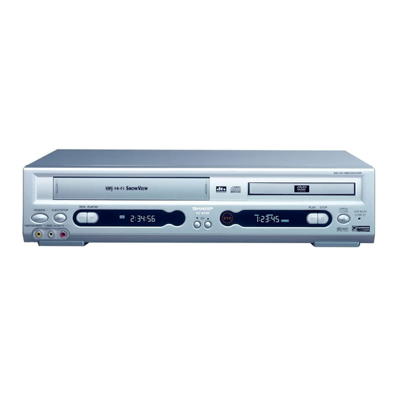
VCR/DVD COMBINATION MODEL
PLAY STOP
OPEN/
CLOSE
VCR DVD
(AV 1 )
MODELS
DVD / CD / VIDEO CD PLAYER
OPEN/
VCR DVD
CLOSE
(LINE 3 )
DVD
PLAY
STOP
OUT
In the interests of user-safety (Required by safety regula-
tions in some countries) the set should be restored to its
original condition and only parts identical to those specified
be used.
QSURROUND
CONTENTS
SHARP CORPORATION
1
S01B9DV-NC55S
DV-NC55S
DV-NC55H
DV-NC60H
Page
DV-NC55S/H
DV-NC60H
Advertisement
Table of Contents

Related Manuals for Sharp DV-NC55S


Summary of Contents for Sharp DV-NC55S
-
Page 1: Table Of Contents
DV-NC55S/H DV-NC60H SERVICE MANUAL S01B9DV-NC55S VCR/DVD COMBINATION MODEL PLAY STOP PLAY OPEN/ POWER EJECT/ STOP CLOSE VCR DVD (AV 1 ) STANDBY CH(TRACKING) AV 2 IN VDEO L(MONO)-AUDIO-R DV-NC55S DV-NC55S/H DV-NC55H DV-NC60H MODELS DVD / CD / VIDEO CD PLAYER... -
Page 2: Important Service Notes
DV-NC55S/H DV-NC60H 1. IMPORTANT SERVICE NOTES • This Unit is classified as a CLASS 1 LASER Note: product. This unit can be used only where the power • The CLASS 1 LASER PRODUCT label is located supply is AC 230V-240V, 50Hz. It cannot be used on the rear cover. -
Page 3: Features
• S-VHS Simple Playback • HQ (High Quality) Circuitry • Simple Recording Timer • Sharp Super Picture Ë Ë Ë Ë Ë DVD • Plays DVD and Audio CD discs as well as CD-R/CD-RW discs recorded in MP3 file format •... - Page 4 DV-NC55S/H DV-NC60H Recording/Playback Time: (SP) 240 min (With E-240 Cassette) (LP) 480 min (With E-240 Cassette) (EP) 720 min (With E-240 Cassette) Channel Coverage: UHF E21-E69 Antenna Input: 75Ω Video Input: Input level: 0.5 to 2.0 Vp-p (75Ω) Video Output: Output level: 1.0 Vp-p (75Ω) Audio Output: Output level: –3.8 dBs (47kΩ)
-
Page 5: Maintenance Check Items And Execution Time
DV-NC55S/H DV-NC60H 5. MAINTENANCE CHECK ITEMS AND EXECUTION TIME MECHANICAL PARTS REGUIRING PERIODICAL INSPECTION Use the following table as a guide to maintain the mechanical parts in good operating condition. Maintained 1,000 hrs. 2,000 hrs. Parts Pickup Spindle Unit Sled Motor... -
Page 6: Disassembly Method
DV-NC55S/H DV-NC60H 6. DISASSEMBLY METHOD 6-1. DISASSEMBLY METHOD 1) Removing the cabinet. (1) Remove the seven screws 1 and 2. 2) Removing the rear panel. (1) Remove the ten screws 3. (2) Remove the three screws 4. 3) Removing the front panel. - Page 7 DV-NC55S/H DV-NC60H (14)Remove the connectors j. (15)Remove the five screws k and l. 6) Removing the cassette housing control/VCR mechanism. (1) Remove the two screws ;. (2) Remove the two screws (3) Remove the one screw 7) Removing the terminal plate.
- Page 8 DV-NC55S/H DV-NC60H 6-2. EXTENSION CABLE USE POINT (FOUR PLACES) Parts Code Price Code Name/Description QCNW-8600AJZZ Extension cable (FFC), 29pin DVD main CN801–INTERFACE CN8202 QCNW-8601AJZZ Extension cable (FFC), 23pin INTERFACE CN8203–DVD display CN5001 QCNW-8605AJZZ Extension cable (FFC), 9pin DVD main CN802–AV SC2003...
- Page 9 DV-NC55S/H DV-NC60H 6-3. REPLACEMENT OF MAIN PARTS <Take out disk> 1. Remove the mechanism with angle from the set (refer to 35 on page 156). 2. It is in such cases as the thin driver, and it is pushed in slowly, and a tray is drawn in the arrow direction the slide rack on the left of the base chassis.
-
Page 10: Operation Of Pickup
DV-NC55S/H DV-NC60H 7. OPERATION OF PICKUP 7-1. CIRCUIT CONFIGURATION OF PICKUP The pickup unit reads signals from the disk, and the flexible cable is connected to the board. The following signals flow through the cable. 7-3. POLARITIES OF SIGNAL 7-2. EQUIVALENT CIRCUIT OF PICKUP... -
Page 11: Adjustment, Replacement And Assembly Of Mechanical Units
DV-NC55S/H DV-NC60H 8. ADJUSTMENT, REPLACEMENT AND ASSEMBLY OF MECHANICAL UNITS The explanation given below relates to the on-site general service (field service) but it does not relates to the adjustment and replacement which need high-grade equipment, jigs and skill. For example, the drum assembling, replacement and adjustment service must be performed by the person who have finished the technical courses. - Page 12 DV-NC55S/H DV-NC60H 8-2. MAINTENANCE CHECK ITEMS AND EXECUTION TIME Perform the maintenance with the regular intervals as follows so as to maintain the quality of machine. 1000 1500 2000 Possible symptom Maintained Remarks hrs. hrs. hrs. hrs. encountered Parts Abnormal rotation or significant Guide roller ass’y...
- Page 13 DV-NC55S/H DV-NC60H 8-3. FUNCTION OF MAJOR MECHANICAL PARTS (TOP VIEW) Function Function Full erase head Reverse guide lever ass’y Supply pole base ass’y Casecon drive gear Tension arm ass’y Take-up reel disk Idler wheel ass’y Pinch roller lever ass’y Pinch drive lever ass’y Drum ass’y...
- Page 14 DV-NC55S/H DV-NC60H FUNCTION OF MAJOR MECHANICAL PARTS (BOTTOM VIEW) Function Function Slow brake Clutch lever Master cam Limiter pulley ass'y Capstan D.D. motor Casecon drive gear Reel belt Shifter...
- Page 15 DV-NC55S/H DV-NC60H 8-4. DISASSEMBLING THE MECHANISM/MAIN PWB ASSEMBLY 2. Removing the mechanism and cassette housing. 1. When removing the mechanism from the main PWB. Remove 2 screws 3 fixing the cassette housing to the Remove the PWB bottom plate 1 screw 1.
- Page 16 DV-NC55S/H DV-NC60H 8-5. CARES WHEN REASSEMBLING cassette housing. (Conditions: When mechanism and PWB INSTALLING THE CASSETTE HOUSING have been installed) When the cassette housing is installed on the mechanism, the initial setting is essential condition. 2. Mechanical initial setting There are two initial setting methods, namely electrical and Feed the pulley feed gear of loading motor with screw mechanical.
- Page 17 DV-NC55S/H DV-NC60H 8-6. REMOVING AND INSTALLING THE CAS- Notes: SETTE HOUSING 1. When fitting the S/E sensor holder to the cassette controller frame L/R, take care. • Removal 2. Misengagement of teeth of casecon drive gear and drive 1. In the cassette removing mode, remove the cassette.
- Page 18 DV-NC55S/H DV-NC60H 8-8. REEL DISK REPLACEMENT AND HEIGHT Notes: CHECK 1. When installing the reel disk, take due care so that the • Removal tension band ass'y is not deformed and grease does no 1. Remove the cassette housing control assembly.
- Page 19 DV-NC55S/H DV-NC60H 2. Whenever replacing the reel disk, perform the height Notes: checking and adjustment. 1. Hold the torque gauge by hand so that it is not moved. 2. Do not keep the reel disk in lock state. Do not allow long- time measurement.
- Page 20 DV-NC55S/H DV-NC60H Notes: 8-12.CHECKING AND ADJUSTMENT OF TAKE- 1. Hold the torque gauge by hand so that it is not moved. UP TORQUE IN VIDEO SEARCH REWIND 2. Do not keep the reel disk in lock state. Do not allow long- MODE time measurement.
- Page 21 DV-NC55S/H DV-NC60H 8-13.CHECKING THE VIDEO SEARCH REWIND BACK TENSION • Remove the cassette housing control assembly. • After short-circuiting between TP5102 and TP5103 Tension gauge Pinch roller provided goes left at VCR display PWB, plug in the 8.8~11.8N power cord.
- Page 22 DV-NC55S/H DV-NC60H • Checking Tension pole adjuster adjusting range 1. Set a cassette tape, push the REC button to place the unit in the SP record mode. Now check the tension pole Tension pole adjuster position. 2. Visually check to see if the right edge of the tension pole is within the 2.3 ±...
- Page 23 DV-NC55S/H DV-NC60H • Adjustment • Checking the brake torque at the take-up side 1. If the indication of torque cassette meter is lower than the setting, shift the tension spring engagement to the part A. Torque gauge 2. If the indication of torque cassette meter is higher than the setting, shift the tension spring engagement to the part B.
- Page 24 DV-NC55S/H DV-NC60H 3. Align the left end of gear of A/C head arm with the 8-18. REPLACEMENT OF A/C (AUDIO/CONTROL) punched mark of chassis, tentatively tighten the screws HEAD 1 and 2 so as to ensure smooth motion of A/C head 1.
- Page 25 DV-NC55S/H DV-NC60H 8-19.A/C HEAD HEIGHT ROUGH ADJUSTMENT 8-20.HEIGHT ADJUSTMENT OF REVERSE GUIDE • Setting Azimuth screw 1. Adjust the height from the mechanism chassis to the reverse guide lower flange to 13.38 mm, using the reverse guide height adjustment jig, in tape loading state.
- Page 26 DV-NC55S/H DV-NC60H Notes: 8-21. ADJUSTMENT OF TAPE DRIVE TRAIN 1. Previously set the tracking control in the center position, 1. Tape run rough adjustment and adjust the ATR signal waveform to maximum with X 1 Remove the cassette housing control assembly.
- Page 27 DV-NC55S/H DV-NC60H 3 Next, press the tracking button (+), (–) and change the ATR signal waveform from max to min and from PB CHROMA min to max. At this time adjust the height of supply Signal and take-up side guide roller with the adjustment driver (JiGDRiVER-4) so that the ATR signal wave- form changes nearly parallel.
- Page 28 DV-NC55S/H DV-NC60H 8-23. REPLACEMENT OF DRUM D.D. MOTOR 8-22.REPLACEMENT OF THE CAPSTAN D.D. 1. Set the ejection mode. (DIRECT DRIVE) MOTOR 2. Withdraw the main power plug from the socket. • Remove the mechanism from the main PWB (refer to 8- 4 item 1 When removing the mechanism from the main •...
- Page 29 DV-NC55S/H DV-NC60H 8-24.REPLACING THE UPPER AND LOWER 8-25.ASSEMBLING OF PHASE MATCHING DRUM ASSEMBLY MECHANISM COMPONENTS • Assemble the phase matching mechanism compo- • Replacement (Perform in the numerical order) nents in the following order. 1 Remove the motor as stated in 8-23 D.D. motor replace- 1.
- Page 30 DV-NC55S/H DV-NC60H 1Insert Reverse Guide Lever Ass’y Insert reverse guide lever ass'y 2 Insert pinch drive cam Align here. Turn the reverse guide lever assembly counterclockwise Fit the pinch drive cam so that the notch of pinch to the stopper.
- Page 31 DV-NC55S/H DV-NC60H 1. Make sure that the loading gear is at the Phase-Match- 8-26. INSTALLING THE SHIFTER ing point 1 as shown below. 2. Install, paying attention to insert point 5 and release point 3. Drum 3. For the phase matching at the insert point 1, see the Phase-Matching point 2 as shown below.
- Page 32 DV-NC55S/H DV-NC60H 8-27.INSTALLING THE MASTER CAM (AT 8-28. REPLACEMENT OF LOADING MOTOR • Removal REAR SIDE OF MECHANISM CHASSIS) 1. Make sure beforehand that the shifter is at the point as shown below. 2. Place the master cam in the position as shown below.
- Page 33 DV-NC55S/H DV-NC60H 8-29. ASSEMBLY OF CASSETTE HOUSING 1. Drive Gear and R Drive angle ass’y MSPRT0381AJFJ Apply grease Apply grease Apply grease Figure 8-48. 2. Synchro Gear, Drive Gear L and Drive Gear R LANGF9592AJFW Top surface should be free from scratches or soil.
-
Page 34: Electrical Adjustment
DV-NC55S/H DV-NC60H 9. ELECTRICAL ADJUSTMENT Notes: • Before the adjustment: Electrical adjustments discussed here are often required after replacement of electronic components and mechanical parts such as video heads. Check that the mechanism and all electric components are in good working condition prior to the adjustments, otherwise adjustments can not be completed. - Page 35 DV-NC55S/H DV-NC60H SERVO CIRCUIT ADJUSTMENT ADJUSTMENT OF HEAD SWITCHING POINT CH-1: 1V/div 50µs/div Measuring Dual-trace oscilloscope CH-2 CH-2: 2V/div 50µs/div instrument Colour TV monitor VIDEO OUT Mode Playback Cassette Alignment tape (VROCPSV) 6.5 ± 0.5H (lines) CH-1 V-sync. HEAD Test point Pin(2) of P201 (H.SW.P.) to CH-1,...
- Page 36 DV-NC55S/H DV-NC60H ADJUSTMENT OF PAL SYSTEM FV(False Vertical Sync) OF STILL PICTURE Measuring Colour TV monitor instrument Mode Playback still Cassette Self-recorded tape (SP mode) (See Note below 2) Control Tracking control buttons (+) or (–) Specification No vertical jitter of picture 1.
-
Page 37: Test Mode
DV-NC55S/H DV-NC60H 10. TEST MODE "NO DISC" state "F0" key input (Press the "play" key and the "stop" key for 5 seconds.) F0000000 00000000 <Press the "1" key on the remote control or "stop" key on the main unit.> The preparation date display of the program... - Page 38 DV-NC55S/H DV-NC60H From (1) "3" Key input DYNMIC TEST 30000000 00000000 Laser test mode "1" Key input The tray opens, the DVD laser is lit, LASER TEST spinning is performed and the sled moves to the outer periphery. 30000001 000000DD "1"...
- Page 39 DV-NC55S/H DV-NC60H From (2) Following playback, jump test mode "3" Key input PLAY TEST Load a disc after the tray is opened. 30000001 00000000 "Open/Close" Key input Following playback state (~~~~~~~~ is a sector ID) ~~~~~~~~ Pressing the keys on the remote control mentioned in the table below enables the test jump.
-
Page 40: Troubleshooting
11. TROUBLESHOOTING (DVD) FLOW CHART NO.1 FLOW CHART NO.3 The fluorescent display tube does not light. No operation is possible from the infrared remote control. Is the supply voltage of 5V fed to pin(14) and pin Check the PC 5V line. Operation is possible from the DVD, but no Replace the remote control receiver or replace the (38) of IC5001? - Page 41 FLOW CHART NO.6 FLOW CHART NO.9 The [No Disc] indication. (In case focus servo does Picture do not operate normally. not function.) Set the disc on the disc tray. Is the focus control signal output from the pin(158) Check the pins(10) and (11) of IC701 periphery of IC701? circuit.
- Page 42 FLOW CHART NO.10 Sound do not operate normally. Are the audio interface signals inputted to the pins Check the line between the pins of IC6010 and the Set the disc on the disc tray. of IC6010? pins of IC6004 and the sound mute periphery IC6010 2PIN L OUT circuit.(Q6007-8.)
- Page 43 FLOW CHART NO.4 (VCR) A cassette tape is not take in. FLOW CHART NO.1 Check R717. Is "L" level applied at pin(19) of IC701. The VCR flourescent display tube fails light up. Check start sensor shutter. Are start sensor shutter go to openwhen the Is the supply voltage of 5V feed to pin(7) of IC5101? Check STBY 5V line.
- Page 44 FLOW CHART NO.7 FLOW CHART NO.9 No power is turned on. The drum motor fails to run. Does power control(H) signal at pin(94) of IC701 Check IC701. Is the voltage more than about 2.6V DC given out Check IC1701. change from "L" to "H" level? of pin(58) of IC701.
- Page 45 FLOW CHART NO.14 FLOW CHART NO.12 Drum servo does not function. Picture E-E does not appear. Is there 14.3MHz oscillation at pins(37) and (38) Check peripheral circuit of X701. Is picture signal input into pins(30), (28) and (31) 1 External input mode of IC701? of IC201? •...
- Page 46 FLOW CHART NO.15 Although picture record is possible, color does not appear (E-E mode is possible). Picture (luminance) record is impossible (E-E mode is possible). Is luminance signal (approx. 0.5 Check between the pins(18) and Check the periphery of pin(61) of Is voltage 5V applied to the chroma Vp-p) input to the pin(19) of IC201? (19) of IC201.
- Page 47 FLOW CHART NO.16 Playback picture does not appear (E-E mode is possible). Although picture is played back, color does not appear (E-E mode is possible). Is voltage 5V applied to the chroma Is FM signal (approx. 200mVp-p) Check the periphery of pin(61) of Check between the pins(79) and power terminal pin(61) of IC201? input to the pin(78) of IC201?
- Page 48 FLOW CHART NO.17 Hi-Fi SOUND MODE TROUBLESHOOTING(1) (For Hi-Fi model) No Hi-Fi E-E sound heard <For Hi-Fi mode> <For normal mode> Is there audio signal inputted at Check line ranging from pins Is there audio signal inputted at each input terminal as shown in (31),(30) of IC1701 (NICAM/GR), each input terminal of IC201 as table?
- Page 49 FLOW CHART NO.20 LINEAR SOUND MODE TROUBLESHOOTING(1) (For MONO model) FLOW CHART NO.18 Hi-Fi SOUND MODE TROUBLESHOOTING(2) (For Hi-Fi model) No E-E sound No Hi-Fi sound recording (E-E mode is posible). Is there audio signal inputted at input terminal as Replace IC6301.
- Page 50 FLOW CHART NO.23 NICAM/IGR TROUBLESHOOTING (For Hi-Fi model) FLOW CHART NO.21 LINEAR SOUND MODE TROUBLESHOOTING(2) (For Hi-Fi and MONO model) No NICAM/IGR No linear sound recording (E-E mode is possible) Check the AUDIO MUTE (H) line between pin (99) Is "L" level applied at pin (99) of IC201? of IC201 and pin (21) of IC701.
- Page 51 FLOW CHART NO.24 DECODER TROUBLESHOOTING (For 2 SCART Hi-Fi and MONO model) Not output from 21pin connector in video and audio signal. Check STBY 5V line. Is voltage 5V applied to the video section power terminal at pins(24), (29) of IC2501? Is voltage 12V applied to the audio section power Check STBY 12V line.
- Page 52 (POWER) FLOW CHART NO.1 FLOW CHART NO.5 No power The DVD power cannot be turned on. The fuse blows out even when it is replaced with new one. See FLOW CHART NO.2 <Fuse blown out.>. Does the change from STANDBY LED indicate Is the fuse good? turn-off? Is the normal state restored when once unplugged...
- Page 53 FLOW CHART NO.9 FLOW CHART NO.6 PC -22V is not output. PC 9V is not output. Is -22V voltage supplied at emitter of Q8202? Check the AT -22V line. Is 12V voltage supplied at pin(1) of IC9052? Check the secondary circuit, AT 12V and PC 12V switch(Q9053) circuit.
-
Page 54: Ic Function List
DV-NC55S/H DV-NC60H 12. IC FUNCTION LIST 12-1. IC301 TA1323F RF PROCESSOR Pin No. Terminal name Operation function Terminal DC Voltage(TYP.) Remarks – GND terminal. – P2TP TE+input (CD) P2TN TE–input (CD) LDO2 O Drive ouput 2 – MDI2 Monitor input 2 –... - Page 55 DV-NC55S/H DV-NC60H Pin No. Terminal name Operation function Terminal DC Voltage(TYP.) Remarks Frequency adjustment When EQF is raised, shift to the high frequency side occurs. Adjusting range: GND - Vdd MDI1 Monitor input 1 – LDO1 O Drive output 1 –...
- Page 56 DV-NC55S/H DV-NC60H 12-2. IC501 IX1689GE FLASH MEMORY Pin No. Symbol Type Name and function Byte selection address: When the device is in the x8 mode, the low or high order byte is Input selected. It is not used in the x16 mode.
- Page 57 DV-NC55S/H DV-NC60H • Block Diagram 8-14 Output Output Input Input Buffer Buffer Buffer Buffer I/O Logic BYTE# DATA QUEUE REGISTER Register Register ESRs Data Comparator Input Buffer Y-DECODER Y GATING/SENSING RY/BY# ADDRESS QUEUE Program Erase LATCHES X-DECODER Voltage Switch ADDRESS COUNTER 12-3.
- Page 58 DV-NC55S/H DV-NC60H 12-4. IC504 IX1687GE MICRO COM. • Block Diagram Port D Port E /IRQ7 /IRQ6 /IRQ5 /IRQ4 EXTAL XTAL STBY H8S/2000 CPU WDTOVF Interruption controller /Ø DMAC ROM * /HWR /LWR /LCAS/WAIT/BFEQO /BACK /BREQ /CS0 /CS1 /CS2 /CS3 /SCK1...
- Page 59 DV-NC55S/H DV-NC60H 12-5. IC508 IX1761GE TRACK BUFFER INTERFACE Pin No. Terminal name Operation function VDD1 Supply Digital power supply +3.3V HADR0 Input CPU Address bus HADR1 Input CPU Address bus HADR2 Input CPU Address bus HADR3 Input CPU Address bus...
- Page 60 DV-NC55S/H DV-NC60H Pin No. Terminal name Operation function PDI[8] Output Input DVD/CD data PDI[7] Output Input DVD/CD data PDI[6] Output Input DVD/CD data PDI[5] Output Input DVD/CD data PDI[4] Output Input DVD/CD data PDI[3] Output Input DVD/CD data PDI[2] Output...
- Page 61 DV-NC55S/H DV-NC60H • Block Diagram 75 74 73 72 71 70 69 68 67 66 65 64 63 62 61 60 59 58 57 56 55 54 53 52 51 VDD1 5VBUFO[B] PSYCI 5VBUFI[B] Interface PDRQI 5VBUFO[A] PDCKI 5VBUFI[A] DVDREQ...
- Page 62 DV-NC55S/H DV-NC60H 12-6. IC601 IX1720GE AV DECODER • Terminal description Name Type Description Host interface, CD-DSP interface, sub-code interface (32-pin) Reset input (active Low). When shifting from the assert state to deassert state, RESET# initialization process of this device is started.
- Page 63 DV-NC55S/H DV-NC60H Name Type Description Host interface, CD-DSP interface, sub-code interface (32-pin)...continued Host ready output (active High). Use this signal when the stream is transferred via the host bus. External pull-up resistor is required. Prior to transfer of each packet (1 HRDY O(p.d.)
- Page 64 DV-NC55S/H DV-NC60H Name Type Description Digital audio port (8-pin) Audio master clock I/O. Sampling frequency can be selected among 384fs, 256fs, AMCLK I/O(p.u.) 192fs, and 128fs (programmable). S/PDIF transmitter output. It can be connected to DAC as the fourth audio output S/PDIF (AOUT[3]) O(p.d.)
- Page 65 DV-NC55S/H DV-NC60H • Block Diagram VDDA GNDP STNDBY# RAMDAT4 RAMDAT11 GNDA VDDP RESET# RAMDAT5 SCNENBL VDDP RAMDAT10 VCLKx2 RAMDAT6 GNDP GNDC RAMDAT9 TESTMODE VDDP VDDAAM AMCLK RAMDAT7 GNDAAM GNDP S/PDIF/AOUT3 RAMDAT8 GPIO VDDP PCLK VDDP GNDP AOUT0 AOUT1 RAMDQM AOUT2...
- Page 66 DV-NC55S/H DV-NC60H 12-7. IC602-3 IX0751TA 16M SDRAM Pin No. Terminal Name Name Input Function Clock The system clock input. All other inputs are referenced to the SDRAM on the rising edge of CLK. Clock Enable Controls internal clock signal and when deactivated, the SDRAM will be one of the states among power down, suspend or self refresh.
- Page 67 DV-NC55S/H DV-NC60H 12-8. IC701 TC94A03F SERVO/DATA PROCESSOR Pin No. Terminal Name In/Output Operation function 3/5V system Remarks ASLCN Output Data slice negative pole output 3V system Analog output terminal ASLCO Output Analog data slice output 3V system Analog output terminal...
- Page 68 DV-NC55S/H DV-NC60H Pin No. Terminal Name In/Output Operation function 3/5V system Remarks – – SMCK Output 22M system clock output 5V system VMCK Output Data output system (signal processing 5V system system) clock output VDD3 – 3.3V digital power supply –...
- Page 69 DV-NC55S/H DV-NC60H Pin No. Terminal Name In/Output Operation function 3/5V system Remarks BD13 BD14 In/Output External RAM data I/O 5V system BD15 – – VDD3 – 3.3V digital power supply – PLCK In/Output PLL system clock I/O 3V system TESM5 –...
- Page 70 DV-NC55S/H DV-NC60H Pin No. Terminal Name In/Output Operation function 3/5V system Remarks EXTAD Input General-purpose external ADC input 3V system Analog input terminal VREF – Reference power supply for analog system 3V system only: 1.65V Output Focus EQ output 3V system...
- Page 71 DV-NC55S/H DV-NC60H 12-9. IC702 IX3420CE 4M EDO DRAM Terminal Terminal name Function 16-19, 22-26 Address inputs. Row address strobe. UCAS Column address strobe/upper byte control. LCAS Column address strobe/lower byte control. Write enable. Output enable. 2-5, 7-10 Data inputs/outputs. 31-34, 36-39 1, 6, 20 +3.3V power supply.
- Page 72 DV-NC55S/H DV-NC60H 12-10. IC5001 PT6312LQ FL DRIVER Pin No. Terminal name Operation function SW1 to SW4 General purpose input pins DOUT Data output pin (N-Channel, Open-Drain) This pin outputs serial data at the falling edge of the shift clock (starting from the lower bit).
- Page 73 DV-NC55S/H DV-NC60H 12-11. IC6001 PCM1737 AUDIO DAC Pin No. Terminal name Operation function LRCK LRCK clock input (fs) DATA Audio • Data input Bit clock input for data. CLKO System clock buffered output. SCLK System clock input. DGND – Digital ground.
- Page 74 DV-NC55S/H DV-NC60H 12-12. IC7701 BA5984FP MOTOR DRIVER Pin No. Terminal name Operation function Pin No. Terminal name Operation function LD-FWD Loading driver FWD input terminal V04(+) Driver CH4 Negative output SL_IN(+) CH1 Former stage amplifier nonreverse input terminal V04(-) Driver CH4 Positive output...
- Page 75 DV-NC55S/H DV-NC60H 12-13. IC8201 IX1757GE INTERFACE MICOM. • Terminal description Pin No. Terminal Name In/Output Operation function TRAY ACK(L) Input Input terminal of [TRAY ACK] from DVD microcomputer DVD LED(L) Output DVD LED control terminal It outputs [L] and is lit during DVD output.
- Page 76 DV-NC55S/H DV-NC60H • Block Diagram...
- Page 77 DV-NC55S/H DV-NC60H - M E M O -...
-
Page 78: Block Diagrams
DV-NC55S/H DV-NC55S/H DV-NC60H DV-NC60H 13. BLOCK DIAGRAMS 13-1. SYSTEM SERVO BLOCK DIAGRAM FROM INTERFACE BLOCK DUB(H) DUB(H) (FROM PIN 37 OF IC8201) (TO BASE OF Q503, Q302 AND Q205) EJECT/STOP /STOP 82~83... - Page 79 DV-NC55S/H DV-NC55S/H DV-NC60H DV-NC60H 13-2. MAIN BLOCK DIAGRAM 84~85...
- Page 80 DV-NC55S/H DV-NC55S/H DV-NC60H DV-NC60H 13-3. SIGNAL FLOW BLOCK DIAGRAM EE Signal PB Luminance Signal REC Luminance Signal PB Chrominance Signal REC Chrominance Signal 86~87...
- Page 81 DV-NC55S/H DV-NC55S/H DV-NC60H DV-NC60H 13-4. AUDIO BLOCK DIAGRAM EE Signal PB Signal REC Signal 88~89...
- Page 82 DV-NC55S/H DV-NC55S/H DV-NC60H DV-NC60H 13-5. POWER BLOCK DIAGRAM 90~91...
-
Page 83: Schematic Diagrams
DV-NC55S/H DV-NC55S/H DV-NC60H DV-NC60H 14. SCHEMATIC DIAGRAMS 14-1. DVD MAIN (1) CIRCUIT SCHEMATIC DIAGRAM 92~93... - Page 84 DV-NC55S/H DV-NC55S/H DV-NC60H DV-NC60H 14-2. DVD MAIN (2) CIRCUIT SCHEMATIC DIAGRAM 94~95...
- Page 85 DV-NC55S/H DV-NC60H 14-3. VCR DISPLAY CIRCUIT SCHEMATIC DIAGRAM...
- Page 86 DV-NC55S/H DV-NC60H 14-4. DVD DISPLAY CIRCUIT SCHEMATIC DIAGRAM...
- Page 87 DV-NC55S/H DV-NC55S/H DV-NC60H DV-NC60H 14-5. AV CIRCUIT SCHEMATIC DIAGRAM 98~99...
- Page 88 DV-NC55S/H DV-NC55S/H DV-NC60H DV-NC60H 14-6. TERMINAL CIRCUIT SCHEMATIC DIAGRAM 100~101...
- Page 89 DV-NC55S/H DV-NC55S/H DV-NC60H DV-NC60H å AND SHADED COMPONENTS=SAFETY RELATED PARTS 14-7. POWER CIRCUIT SCHEMATIC DIAGRAM 102~103...
- Page 90 DV-NC55S/H DV-NC55S/H DV-NC60H DV-NC60H 14-9. VCR MAIN (1) CIRCUIT SCHEMATIC DIAGRAM 106~107...
- Page 91 DV-NC55S/H DV-NC55S/H DV-NC60H DV-NC60H 14-10. VCR MAIN (2) CIRCUIT SCHEMATIC DIAGRAM 108~109...
- Page 92 DV-NC55S/H DV-NC55S/H DV-NC60H DV-NC60H å AND SHADED COMPONENTS=SAFETY RELATED PARTS 14-11. VCR MAIN (3) CIRCUIT SCHEMATIC DIAGRAM å 110~111...
- Page 93 DV-NC55S/H DV-NC55S/H DV-NC60H DV-NC60H 14-12. VCR MAIN (4) CIRCUIT SCHEMATIC DIAGRAM 112~113...
-
Page 94: Printed Wiring Board Assemblies
DV-NC55S/H DV-NC60H 15. PRINTED WIRING BOARD ASSEMBLIES DVD MAIN PWB Component Side SIDE A Q308 CN702 CN701 Q309 C213 TP831 TP318 C210 TP7705TP7704TP7703 TP7702TP7701 TP7711TP7710TP7709 TP7708TP7707TP7706 TP320 TP322 R341 C309 C302 TP323 TP832 R342 C212 R311 TP321 TP333 TP833 R336... - Page 95 DV-NC55S/H DV-NC60H Wiring Side SIDE A...
- Page 96 DV-NC55S/H DV-NC60H Component Side SIDE B CN302 R323 C707 R321 R315 R707 C305 R310 Q701 L702 C729 Q301 D301 C710 R728 C728 C705 C716 R304 C304 C706 R708 C709 TP712 C306 TP701 C737 R738 R737 C319 C738 C708 R740 R739...
- Page 97 DV-NC55S/H DV-NC60H VCR DISPLAY PWB Component Side SIDE A Wiring Side SIDE A Component Side SIDE B Wiring Side SIDE B...
- Page 98 DV-NC55S/H DV-NC60H DVD DISPLAY PWB Component Side SIDE A Wiring Side SIDE A Component Side SIDE B Wiring Side SIDE B...
- Page 99 DV-NC55S/H DV-NC60H AV PWB Component Side SIDE A Wiring Side SIDE A...
- Page 100 DV-NC55S/H DV-NC60H Component Side SIDE B Q2316 Q2014 Q2006 R2341 R6061 Q2311 Q2309 Q2315 Q2310 Q2313 R2340 R2339 R6075 Q2005 R6076 C2018 IC2001 Q2317 R6068 R6175 R2001 Q2003 R6176 Q6010 Q2001 C2019 R2004 R2011 Q2004 Q6110 Q2002 R2012 R6069 Q6012...
- Page 101 DV-NC55S/H DV-NC60H TERMINAL PWB Component Side SIDE A Wiring Side SIDE A...
- Page 102 DV-NC55S/H DV-NC60H Component Side SIDE B Wiring Side SIDE B...
- Page 103 DV-NC55S/H DV-NC60H POWER PWB Component Side SIDE A Wiring Side SIDE A...
- Page 104 DV-NC55S/H DV-NC60H Component Side SIDE B Wiring Side SIDE B...
- Page 105 DV-NC55S/H DV-NC60H INTERFACE PWB Component Side SIDE A Wiring Side SIDE A...
- Page 106 DV-NC55S/H DV-NC60H Component Side SIDE B Wiring Side SIDE B...
- Page 107 DV-NC55S/H DV-NC55S/H DV-NC60H DV-NC60H VCR MAIN PWB Component Side SIDE A 128~129...
- Page 108 DV-NC55S/H DV-NC55S/H DV-NC60H DV-NC60H Wiring Side SIDE A 130~131...
- Page 109 DV-NC55S/H DV-NC55S/H DV-NC60H DV-NC60H Component Side SIDE B 132~133...
- Page 110 DV-NC55S/H DV-NC55S/H DV-NC60H DV-NC60H Wiring Side SIDE B 134~135...
- Page 111 DV-NC55S/H DV-NC60H - M E M O -...
-
Page 112: Replacement Parts List
DV-NC55S/H DV-NC60H 16. REPLACEMENT PARTS LIST/ Ref. No. Part No. Description Code Ref. No. Part No. Description Code EXPLODED VIEWS IC702 RH-iX3420CEZZ J IX3420CE, 4M EDO DRAM AT IC705 VHiNJM12904-1 J NJM12904 IC7701 VHiBA5984FP-1 J BA5984FP, Motor Driver ELECTRICAL PARTS LIST... - Page 113 DV-NC55S/H DV-NC60H Ref. No. Part No. Description Code Ref. No. Part No. Description Code DUNTK6054TE6E C726 VCKYCY1CB104K J 0.1 16V Ceramic DVD MAIN PWB UNIT(Continued) C727 VCKYCY1CB104K J 0.1 16V Ceramic C728 VCCCCY1HH221J J 220p 50V Ceramic C508 VCKYCY1CB104K J 0.1...
- Page 114 DV-NC55S/H DV-NC60H Ref. No. Part No. Description Code Ref. No. Part No. Description Code DUNTK6054TE6E R728 VRS-CY1JF331J J 330 1/16W Metal Oxide AA DVD MAIN PWB UNIT(Continued) R729 VRS-CY1JF393J J 39k 1/16W Metal Oxide AA R730 VRS-CY1JF273J J 27k 1/16W Metal Oxide AA...
- Page 115 DV-NC55S/H DV-NC60H Ref. No. Part No. Description Code Ref. No. Part No. Description Code DUNTK6054TE6E R5116 VRD-RA2BE822J J 8.2k 1/8W Carbon DVD MAIN PWB UNIT(Continued) (NC60H) R5116 VRS-CY1JF822J J 8.2k 1/16W Metal Oxide AA R801 RBLN-0076TAZZ J Balun, BLN-0076TA (NC55S/H)
- Page 116 DV-NC55S/H DV-NC60H Ref. No. Part No. Description Code Ref. No. Part No. Description Code DUNTKB041TEV1(DV-NC55S/H) C2009 VCEA9M0JW107M J 100 6.3V Electrolytic DUNTKB085TEV1(DV-NC60H) C2010 VCEA9M1CW106M J 10 16V Electrolytic DVD DISPLAY PWB UNIT C2011 VCEA9M1CW106M J 10 16V Electrolytic C2012 VCEA9M1CW106M J 10...
- Page 117 DV-NC55S/H DV-NC60H Ref. No. Part No. Description Code Ref. No. Part No. Description Code DUNTKB045TEV1 C2508 VCEA9M1CW106M J 10 16V Electrolytic AV PWB UNIT(Continued) C2509 VCEA9M1HW105M J 1 50V Electrolytic C2510 VCEA9M1HW105M J 1 50V Electrolytic R6176 VRS-CY1JF000J 1/16W Metal Oxide AA...
- Page 118 DV-NC55S/H DV-NC60H Ref. No. Part No. Description Code Ref. No. Part No. Description Code DUNTKB046TEV1 å D910 RH-DX0220CEZZ J DX0220CE TERMINAL PWB UNIT(Continued) å D911 RH-DX0220CEZZ J DX0220CE å D912 RH-DX0220CEZZ J DX0220CE å D913 RH-DX0220CEZZ J DX0220CE R2560 VRS-CY1JF183J...
- Page 119 DV-NC55S/H DV-NC60H Ref. No. Part No. Description Code Ref. No. Part No. Description Code DUNTKB047TEV1(DV-NC55S/H) DUNTKB040TEV1(DV-NC55S/H) DUNTKB087TEV1(DV-NC60H) DUNTKB084TEV1(DV-NC60H) POWER PWB UNIT(Continued) INTERFACE PWB UNIT å R908 VRD-RA2BE563J J 56k 1/8W Carbon INTEGRATED CIRCUITS å R909 VRS-CY1JF473J J 47k 1/16W Metal Oxide AA...
- Page 120 DV-NC55S/H DV-NC60H Ref. No. Part No. Description Code Ref. No. Part No. Description Code DUNTKB040TEV1(DV-NC55S/H) R8207 VRS-CY1JF473J J 47k 1/16W Metal Oxide AA DUNTKB084TEV1(DV-NC60H) R8208 VRS-CY1JF103J J 10k 1/16W Metal Oxide AA INTERFACE PWB UNIT(Continued) R8209 VRS-CY1JF103J J 10k 1/16W Metal Oxide AA...
- Page 121 DV-NC55S/H DV-NC60H Ref. No. Part No. Description Code Ref. No. Part No. Description Code DUNTKB043TEV1(DV-NC55H/60H) CAPACITORS DUNTKB043TEV2(DV-NC55S) C201 VCEA9M0JW107M J 100 6.3V Electrolytic VCR MAIN PWB UNIT(Continued) C202 VCKYCY1EF104Z J 0.1 25V Ceramic C203 VCCCCY1HH121J J 120p 50V Ceramic Q602...
- Page 122 DV-NC55S/H DV-NC60H Ref. No. Part No. Description Code Ref. No. Part No. Description Code DUNTKB043TEV1(DV-NC55H/60H) C776 VCKYCY1EF104Z J 0.1 25V Ceramic DUNTKB043TEV2(DV-NC55S) C780 VCKYCY1CB473K J 0.047 16V Ceramic VCR MAIN PWB UNIT(Continued) C781 VCKYCY1EB103K J 0.01 25V Ceramic C794 VCCCCY1HH6R0D J 6p...
- Page 123 DV-NC55S/H DV-NC60H Ref. No. Part No. Description Code Ref. No. Part No. Description Code DUNTKB043TEV1(DV-NC55H/60H) R610 VRS-CY1JF473J J 47k 1/16W Metal Oxide AA DUNTKB043TEV2(DV-NC55S) R611 VRS-CY1JF562J J 5.6k 1/16W Metal Oxide AA VCR MAIN PWB UNIT(Continued) R612 VRS-CY1JF104J J 100k 1/16W Metal Oxide AA...
- Page 124 DV-NC55S/H DV-NC60H Ref. No. Part No. Description Code Ref. No. Part No. Description Code DUNTKB043TEV1(DV-NC55H/60H) R9909 VRD-RM2HD182J J 1.8k 1/2W Carbon DUNTKB043TEV2(DV-NC55S) R9910 VRS-CY1JF221J J 220 1/16W Metal Oxide AA VCR MAIN PWB UNIT(Continued) R9911 VRD-RM2HD562J J 5.6k 1/2W Carbon...
- Page 125 DV-NC55S/H DV-NC60H Ref. No. Part No. Description Code Ref. No. Part No. Description Code SUPPLIED ACCESSORIES MECHANISM PARTS (VCR PART) QCNW-8077UMZZ U 21Pin Cable LBNDK1011AJZZ J Tension Band Ass’y QCNW-7870UMZZ U RF Cable LBOSZ1007AJZZ J Tension Arm boss RRMCGA005WJSA U Remote Control Unit...
- Page 126 DV-NC55S/H DV-NC60H Ref. No. Part No. Description Code Ref. No. Part No. Description Code SCREW, NUTS AND WASHERS CABINET PARTS XBPSD26P08000 J Screw 2.6P+8S A/C Head AA CCABA3167TEV1 U Top Cabinet Ass'y 202-1 XHPSD26P06WS0 J C2.6P+6S(A/C) CPNLC2990TEV1 U KS Panel(NC55H)
- Page 127 DV-NC55S/H DV-NC60H Ref. No. Part No. Description Code Ref. No. Part No. Description Code XHPSF30P10WS0 J Screw PSPAZ0641AJZZ J Spacer PSLDM9385AJZZ J Spacer PSLDM4591AJFW J Shild Plate(NC55S/H) TLABS0417AJZZ J Laser Caution Label GCOVA3065AJZZ U Rear Panel QCNW-A226WJZZ U Connecting Cord...
- Page 128 DV-NC55S/H DV-NC60H MECHANISM EXPLODED VIEW (DVD PART) Ref. No. Part No. Description Code Ref. No. Part No. Description Code Dry Coating Dry Coating Dry Coating Dry Coating Grease Grease 401-11 401-13 401-10 Grease 401-12 Grease 401-4 401-3 401-2 Grease 401-5 å...
- Page 129 DV-NC55S/H DV-NC60H MECHANISM EXPLODED VIEW (VCR PART) Ref. No. Part No. Description Code Ref. No. Part No. Description Code 202-1 202-2 535-1 535-2...
- Page 130 DV-NC55S/H DV-NC60H CASSETTE HOUSING CONTROL EXPLODED VIEW Ref. No. Part No. Description Code Ref. No. Part No. Description Code...
- Page 131 DV-NC55S/H DV-NC60H CABINET EXPLODED VIEW Ref. No. Part No. Description Code Ref. No. Part No. Description Code DV-NC55S/H DV-NC60H...
- Page 132 DV-NC55S/H DV-NC60H FRONT PANEL EXPLODED VIEW(DV-NC55S/H) Ref. No. Part No. Description Code Ref. No. Part No. Description Code 601-10 601-7 601-3 601-9 601-5 601-1 601-10 601-6 601-4 601-12 601-2...
- Page 133 DV-NC55S/H DV-NC60H FRONT PANEL EXPLODED VIEW(DV-NC60H) Ref. No. Part No. Description Code Ref. No. Part No. Description Code 601-9 601-8 601-5 601-6 601-7 601-10 601-1 601-3 601-2 601-4...
-
Page 134: Packing Of The Set
DV-NC55S/H DV-NC60H 17. PACKING OF THE SET Ref. No. Part No. Description Code Ref. No. Part No. Description Code No.5 No.4 No.3 No.7 No.1, 2 No.9 No.8 No.6 ACCESSORIES PACKING PARTS (NOT REPLACEMENT ITEM) Model Parts Code Description Remarks Model... - Page 135 Part No. Description Code © COPYRIGHT 2001 BY SHARP CORPORATION ALL RIGHTS RESERVED. No part of this publication may be reproduced, stored in a retrieval system, or transmitted in any form or by any means, electronic, mechanical, photocopying, recording, or otherwise, without prior written permission of the publisher.