Advertisement
Quick Links
Advertisement

Related Manuals for Bosch TC9320


Summary of Contents for Bosch TC9320
- Page 1 TC9320, TC9320C Instruction Manual EN Indoor Ceiling Housings...
-
Page 2: Important Safeguards
3. Heed Warnings - All warnings on the unit and in the replace it properly in its carton and notify the shipper. If any operating instructions should be adhered to. items are missing, notify your Bosch Sales Representa- 4. Follow Instructions - All operating and user instructions tive or Customer Service. -
Page 3: Product Instructions
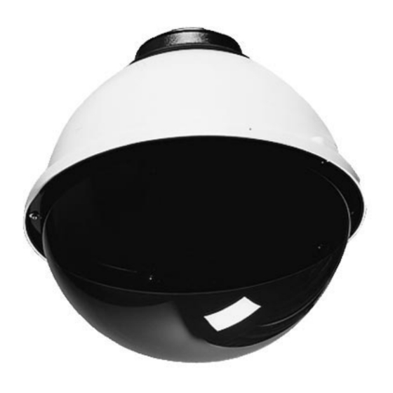
Figure 1 PRODUCT INSTRUCTIONS MODELS TC9320/TC9320C Description: A discreet housing system designed for outdoor Ceiling Coupling CEILING COUPLING applications. Heaters and blowers are available as options. 32-VL135 Designed for pendant mounting, but can be wall, pole, or roof mount with optional brackets. Unit is also available with liner assembles with "L"... - Page 4 PAN/TILT AND LINER ASSEMBLIES TC6410PT a. Mount the metal arms to the metal adapter brackets (30- TC6270PT TC6410PT TC6280PT VL383 using the #6-32 x 1/2" bolts, lockwashers, and hex nuts. Refer to fig. 2 & 3 for proper orientation and placement. NOTE: For proper operation of pan/tilt, it is important that bolt head is oriented against the metal adapter bracket, not the Figure 2...
- Page 5 BLOWER Figure 5 ELECTRICAL ACCESSORIES INSTRUCTIONS #6-32 BOLTS The TC9320 (L) housing can be purchased with optional silicon strip heaters and a muffin-type blower. The standard housing includes the terminal block with cover, as well as the terminal THERMOSTAT bracket used to mount this equipment to the mounting bracket.
-
Page 6: Side View
with (2) #6-32 bolts, as shown in Fig. 6. Wiring Diagram 1) Use the diagram below to complete electrical con- 6) Connect the female lead on the heater wire to one of the nections, for 24 VAC units. HT 36121 and BT 36122 are posts on the thermostat. - Page 8 The Netherlands Republic of Singapore Fax: 1-717-735-6560 Tele +31 40 27 80000 Tel: 65 (6) 319 3486 www.boschsecuritysystems.com © 2004 Bosch Security Systems GmbH 3935 890 16812 04-33 | Updated August 10, 2004 | Data subject to change without notice.