Table of Contents
Advertisement
Quick Links
Notes: This model's DVD changer mechanism unit is CRS1D. Please refer to the original Service Manual
(Order No. MD0603065A3) for this mechanism.
Specifications
AMPLIFIER SECTION
RMS Output Power: Dolby Digital Mode
Front Ch (High Ch)
Front Ch (Low Ch)
Surround Ch
Center Ch
Subwoofer Ch
Total RMS Dolby Digital mode power
110 W per channel (3 Ω), 1 kHz,
10% THD
55 W per channel (6 Ω), 100 Hz,
10% THD
110 W per channel (3 Ω), 1 kHz,
10% THD
110 W per channel (3 Ω), 1 kHz,
10% THD
110 W per channel (3 Ω), 100 Hz,
10% THD
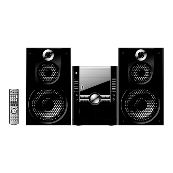
DVD Stereo System
SA-VK960GC
SA-VK960GCS
SA-VK960GCT
SA-VK960GS
Colour
(K)... Black Type
PMPO output power
FM/AM TUNER, TERMINALS SECTION
Preset station
Frequency Modulation (FM)
Frequency range
Sensitivity
S/N 26 dB
Antenna terminals
Amplitude Modulation (AM)
© 2007 Matsushita Electric Industrial Co. Ltd.. All
rights
reserved.
distribution is a violation of law.
ORDER NO. MD0707009CE
880 W
10000 W
FM 20 stations
AM 15 stations
87.50 to 108.00 MHz (50 kHz
step)
4.0 µV (IHF)
2.2 µV
75 Ω (unbalanced)
Unauthorized
copying
and
Advertisement
Table of Contents

Related Manuals for Panasonic SA-VK960GC


Summary of Contents for Panasonic SA-VK960GC
-
Page 1: Specifications
ORDER NO. MD0707009CE DVD Stereo System SA-VK960GC SA-VK960GCS SA-VK960GCT SA-VK960GS Colour (K)... Black Type Notes: This model’s DVD changer mechanism unit is CRS1D. Please refer to the original Service Manual (Order No. MD0603065A3) for this mechanism. Specifications AMPLIFIER SECTION 880 W... - Page 2 Media file format support MP3 (*.mp3) narrow pictures may not be displayed. WMA (*.wma) MPEG4 data recorded with the Panasonic SD multi cameras or JPEG (*.jpg, *.jpeg) DVD video recorders. MPEG4 (*.asf) Conforming to SD VIDEO specifications (ASF standard) / MPEG4...
- Page 3 SA-VK960GC / SA-VK960GCS / SA-VK960GCT / SA-VK960GS Notes: 1. Specifications are subject to change without notice. Mass and dimensions are approximate. 2. Total harmonic distortion is measured by the digital spectrum analyzer. SYSTEM Refer to the respective original service manuals for *1, *2, *3, *4.
-
Page 4: Table Of Contents
SA-VK960GC / SA-VK960GCS / SA-VK960GCT / SA-VK960GS CONTENTS Page Page 1 Safety Precautions 10.17. Replacement of Cassette Lid 1.1. General Guidelines 10.18. Disassembly of Deck P.C.B 1.2. Safety Precaution for AC Power Supply Cord (For GS 10.19. Disassembly of D-Amp P.C.B. & Speaker P.C.B. - Page 5 SA-VK960GC / SA-VK960GCS / SA-VK960GCT / SA-VK960GS 18.5. Deck Circuit 20.1. Basic Troubleshooting Guide for Traverse Unit (DVD 18.6. D-Amp Circuit Module P.C.B) 18.7. SMPS Circuit 21 Terminal Function of IC 18.8. Speaker/Optical Pickup Unit Circuit 19 Printed Circuit Board 21.1.
-
Page 6: Safety Precautions
SA-VK960GC / SA-VK960GCS / SA-VK960GCT / SA-VK960GS 1 Safety Precautions 1.1. General Guidelines 1. When servicing, observe the original lead dress. If a short circuit is found, replace all parts which have been overheated or damaged by the short circuit. -
Page 7: Safety Precaution For Ac Power Supply Cord (For Gs Only)
SA-VK960GC / SA-VK960GCS / SA-VK960GCT / SA-VK960GS 1.2. Safety Precaution for AC Power Supply Cord (For GS only) Before use Remove the connector cover. How to replace the fuse The location of the fuse differs according to the type of AC power plug (fi gures A and B). -
Page 8: Safety Parts Information
SA-VK960GC / SA-VK960GCS / SA-VK960GCT / SA-VK960GS 1.6. Safety Parts Information Safety Parts List: There are special components used in this equipment which are important for safety. These parts are marked by in the Schematic Diagrams & Replacement Parts List. It is essential that these critical parts should be replaced with manufacturer’s specified parts to prevent shock, fire or other hazards. -
Page 9: Prevention Of Electrostatic Discharge (Esd) To
SA-VK960GC / SA-VK960GCS / SA-VK960GCT / SA-VK960GS 2 Prevention of Electrostatic Discharge (ESD) to Electrostatically Sensitive (ES) Devices Some semiconductor (solid state) devices can be damaged easily by electricity. Such components commonly are called Electrostatically Sensitive (ES) Devices. Examples of typical ES devices are integrated circuits and some field-effect transistors and semiconductor “chip”... -
Page 10: Precaution Of Laser Diode
SA-VK960GC / SA-VK960GCS / SA-VK960GCT / SA-VK960GS 3 Precaution of Laser Diode CAUTION : This product utilizes a laser diode with the unit turned on, invisible laser radiation is emitted from the pickup lens. Wavelength : 662nm (DVD)/785nm (CD) Maximum output radiation power from pickup : 100µW/VDE Laser radiation from pickup unit is safety level, but be sure the followings: 1. -
Page 11: About Lead Free Solder (Pbf)
SA-VK960GC / SA-VK960GCS / SA-VK960GCT / SA-VK960GS 4 About Lead Free Solder (PbF) 4.1. Service caution based on legal restrictions 4.1.1. General description about Lead Free Solder (PbF) The lead free solder has been used in the mounting process of all electrical components on the printed circuit boards used for this equipment in considering the globally environmental conservation. -
Page 12: Handling Precautions For Traverse Unit
SA-VK960GC / SA-VK960GCS / SA-VK960GCT / SA-VK960GS 5 Handling Precautions for Traverse Unit The laser diode used inside optical pickup could be destroyed due to static electricity as a potential difference is caused by electrostatic load discharged from clothes or human body. Handling the parts carefully to avoid electrostatic destruction during repair. - Page 13 SA-VK960GC / SA-VK960GCS / SA-VK960GCT / SA-VK960GS Fig. 5.2...
-
Page 14: Accessories
SA-VK960GC / SA-VK960GCS / SA-VK960GCT / SA-VK960GS 6 Accessories • • • • Note: Refer to “Replacement Parts List” (Section 23) for the part number. FM antenna wire Remote control AM loop antenna AC cord (For GC/GCS/GCT/GS) Video cable AC cord (For GS only) -
Page 15: Operation Procedures
SA-VK960GC / SA-VK960GCS / SA-VK960GCT / SA-VK960GS 7 Operation Procedures 7.1. Main Unit Key Buttons Operations Refer to the numbers in parentheses for page reference. Buttons such as function the same as the controls on the remote control. AC supply indicator [AC IN]... -
Page 16: Remote Control Key Buttons Operations
SA-VK960GC / SA-VK960GCS / SA-VK960GCT / SA-VK960GS 7.2. Remote Control Key Buttons Operations Buttons labelled such as function in exactly the same way as the buttons on the main unit. Television operations [CLOCK/TIMER] [SLEEP/A.OFF] [ PLAY/REC] Numeric [DISC] [DIMMER] [PLAY MODE... -
Page 17: Portable Audio Equipment Connection & Operation
SA-VK960GC / SA-VK960GCS / SA-VK960GCT / SA-VK960GS 7.3. Portable Audio Equipment Connection & Operation Before connection Disconnect the AC power supply cord. Turn off all equipment and read the appropriate operating instructions. The equipment connections described are examples only. Peripheral equipment and optional cables are sold separately unless otherwise indicated. -
Page 18: Usb Connection & Operation
SA-VK960GC / SA-VK960GCS / SA-VK960GCT / SA-VK960GS 7.4. USB Connection & Operation The USB connectivity enables you to connect and play tracks or les from USB mass storage class devices. Typically, USB memory devices. (Bulk only transfer) Preparation Before connecting any USB mass storage device to the unit, ensure that the data stored therein has been backed up. -
Page 19: About Divx Vod Content
SA-VK960GC / SA-VK960GCS / SA-VK960GCT / SA-VK960GS 7.5. About DivX VOD Content DivX Video-on-Demand (VOD) content is encrypted for Regarding DivX content that can only be played a copyright protection. In order to play DivX VOD content on set number of times this unit, you first need to register the unit. -
Page 20: Disc Information
Closing the session will also work. MPEG4 data recorded with the Panasonic SD multi cameras or DVD video recorders [conforming to SD VIDEO specifications (ASF standard)/MPEG4 (Simple Pro file) video system/G.726 audio system]. - Page 21 SA-VK960GC / SA-VK960GCS / SA-VK960GCT / SA-VK960GS 7.6.2. File Extension Type Support (WMA/MP3/JPEG/MPEG4/DivX) When there are more than eight groups, the eighth group (Extension: ".JPG", ".jpg", ".JPEG" or ".jpeg") onwards will be displayed on one vertical line in the JPEG fi les taken on a digital camera that conform to DCF menu screen.
-
Page 22: Dvd/Cd Changer Mechanism Unit
SA-VK960GC / SA-VK960GCS / SA-VK960GCT / SA-VK960GS 8 DVD/CD Changer Mechanism Unit 8.1. CRS1D Mechanism Overview... -
Page 23: General Feature
SA-VK960GC / SA-VK960GCS / SA-VK960GCT / SA-VK960GS 8.1.1. General Feature • • • • This is a five disc changer mechanism for CD/DVD. The outline figure is shown below. • • • • The mechanism has "CHANGE WHILE PLAY" function. It open other trays for disc exchanging while one tray is at PLAY position performing recording or reproducing. - Page 24 SA-VK960GC / SA-VK960GCS / SA-VK960GCT / SA-VK960GS Condition Explanation Change The state when one of the opened tray being driven from OPEN position to STOCK position and other opened trays remain still at OPEN position. Close All The state where all open trays will being driven from OPEN position to STOCK position, one by one from...
-
Page 25: Self Diagnosis And Special Mode Setting
SA-VK960GC / SA-VK960GCS / SA-VK960GCT / SA-VK960GS 9 Self Diagnosis and Special Mode Setting This unit is equipped with functions for checking and inspecting. 9.1. Service Mode Summary Table 9.1.1. Service Mode Summary Table (For DVD) The service modes can be activated by pressing various button combination on the main unit and remote control unit. -
Page 26: Service Mode Table (For Dvd)
SA-VK960GC / SA-VK960GCS / SA-VK960GCT / SA-VK960GS 9.2. Service Mode Table (For DVD) By pressing various button combinations on the player and remote control unit can activate the various service modes for checking. Special Note: Due to the limitations of the no. characters that can be shown on FL Display, the “FL Display” button on the remote control unit is used to show the following page. -
Page 27: Service Mode Table
SA-VK960GC / SA-VK960GCS / SA-VK960GCT / SA-VK960GS 9.2.2. Service Mode Table 2 Key Operation Item FL Display Mode Name Description Front Key (Display 1) DVD laser DVD laser drive current measurement. In STOP (no disc) mode, drive current DVD laser drive current is measured... - Page 28 SA-VK960GC / SA-VK960GCS / SA-VK960GCT / SA-VK960GS 9.2.3. Service Mode Table 3 Item Key Operation FL Display Mode Name Description Front Key Micro-processor Micro-processor firmware version In STOP (no disc) (Display 1) firmware version display & EEPROM checksum display. mode, press [STOP] display &...
- Page 29 SA-VK960GC / SA-VK960GCS / SA-VK960GCT / SA-VK960GS Product Region TV Broadcasting Model Series Country Region Signal System Region Display Code OSD Menu Language System (Default) (Default) English, Spanish, Canadian P, PC, PX USA, Canada, PX NTSC NTSC (*A) French Japan...
- Page 30 SA-VK960GC / SA-VK960GCS / SA-VK960GCT / SA-VK960GS 9.2.4. Service Mode Table 4 Item Key Operation FL Display Mode Name Description Front Key DVD Module DVD Module P.C.B. firmware version In STOP (no disc) P.C.B. firmware is displayed on the FL Display.
- Page 31 SA-VK960GC / SA-VK960GCS / SA-VK960GCT / SA-VK960GS 9.2.5. Service Mode Table 5 Item Key Operation FL Display Mode Name Description Front Key Timer 1 check Timer 1 check In STOP (no disc) (Display 1) Laser operation timer is measured mode, press [STOP] separately for DVD laser and CD laser.
- Page 32 SA-VK960GC / SA-VK960GCS / SA-VK960GCT / SA-VK960GS 9.2.6. Optical Pickup Unit Breakdown Diagnosis The unit is equipped with the optical pickup self-diagnosis function and tilt adjustment check function. Follow the procedure described below during repair in order to perform self-diagnosis and tilt adjustment effectively. Especially when "NO DISC" is displayed, be sure to apply the self-diagnosis function before replacing with an optical pickup.
-
Page 33: Service Mode Table (For Inspection)
SA-VK960GC / SA-VK960GCS / SA-VK960GCT / SA-VK960GS 9.3. Service Mode Table (For Inspection) 9.3.1. Service Mode Table 1 Item Key Operation FL Display Mode Name Description Front Key Self-Diagnostic To enter into self-diagnostic checking In DVD/CD or tape mode (ensure no Mode for main unit. - Page 34 SA-VK960GC / SA-VK960GCS / SA-VK960GCT / SA-VK960GS 9.3.2. Service Mode Table 2 Item Key Operation FL Display Mode Name Description Front Key Firmware Version To check the EEPROM checksum and (Condition 1) In Doctor Mode, press [STOP] button Check Micro-P firmware version.
- Page 35 SA-VK960GC / SA-VK960GCS / SA-VK960GCT / SA-VK960GS 9.3.3. Service Mode Table 3 Item Key Operation FL Display Mode Name Description Front Key DVD/CD Changer To check the operation of changer unit In Doctor Mode, press [DISC] button (Display 1) Operation Check for disc change.
- Page 36 SA-VK960GC / SA-VK960GCS / SA-VK960GCT / SA-VK960GS 9.3.4. CD/DVD changer unit ageing test mode Below is the process flow chart of ageing for the CD/DVD changer unit. (CRS1D) Tray 1 Tray 5 Tray 3 Tray 2 Tray 4 MODE 3...
- Page 37 SA-VK960GC / SA-VK960GCS / SA-VK960GCT / SA-VK960GS MODE 3 PLAY-CHANGE-OPEN mode aging (1 cycle) CHANGE while PLAY 4 AGING MODE 3-d ALL OPEN ALL OPEN DISC 5 LOAD DISC 3 LOAD DISC 4 LOAD DISC 2 LOAD WAIT 500ms ALL CLOSE...
-
Page 38: Dvd Self Diagnostic Function-Error Code
SA-VK960GC / SA-VK960GCS / SA-VK960GCT / SA-VK960GS 9.4. DVD Self Diagnostic Function-Error Code 9.4.1. DVD Module Error Code Table Error Diagnosis Contents Description of error Automatic FL Display Remarks Code U702 HDMI/DVI I2C The communication error of I2C Press [... - Page 39 SA-VK960GC / SA-VK960GCS / SA-VK960GCT / SA-VK960GS 9.4.2. Mechanism Error Code Table Error Diagnosis Contents Description of error Automatic FL Display Remarks Code H01 Tray loading error The tray opening and closing is Press [ STOP] on abnormal. CLOSE and OPEN of the main unit for next error.
- Page 40 SA-VK960GC / SA-VK960GCS / SA-VK960GCT / SA-VK960GS 9.4.3. Power Supply Error Code Table Error Diagnosis Contents Description of error Automatic FL Display Remarks Code F61 The abnormalities In normal operation, when DCDET2 Press [ STOP] on in an output or power goes to "L" (Low) (Not during POWER main unit for next error.
- Page 41 SA-VK960GC / SA-VK960GCS / SA-VK960GCT / SA-VK960GS 9.4.5. USB Error Code Table Error Diagnosis Contents Description of error Automatic FL Display Remarks Code F650 USB device: Devices Devices other than the mass storage Press [ STOP] on other than mass class are connected.
- Page 42 SA-VK960GC / SA-VK960GCS / SA-VK960GCT / SA-VK960GS 9.4.6. CD/DVD Changer Mechanism Error Code Table Error Diagnosis Contents Description of error Automatic FL Display Remarks Code IHMS Cam gear abnormality Cam gear does not rotate to For CD/DVD changer unit (CRS1D).
- Page 43 SA-VK960GC / SA-VK960GCS / SA-VK960GCT / SA-VK960GS Error Diagnosis Contents Description of error Automatic FL Display Remarks Code PDRV Cam gear/gear Cam gear does not move from For CD/DVD changer unit (CRS1D). "HOME" to "PLAY" drive assembly abnormal Press [SINGLE CHANGE] on main position.
- Page 44 SA-VK960GC / SA-VK960GCS / SA-VK960GCT / SA-VK960GS 9.4.7. Deck Mechanism Error Code Table Error Diagnosis Contents Description of error Automatic FL Display Remarks Code Mode switch Detection of switch for "On" when the For Deck Mechanism abnormal (Plunger deck mechanism is in the driving Unit (Deck 1/2).
-
Page 45: Sales Demonstration Lock Function
SA-VK960GC / SA-VK960GCS / SA-VK960GCT / SA-VK960GS 9.5. Sales Demonstration Lock Function This function prevents discs from being lost when the unit is used for sales demonstrations by disabling the disc eject function. "LOCKED" is displayed on the unit, and ordinary operation is disabled. - Page 46 SA-VK960GC / SA-VK960GCS / SA-VK960GCT / SA-VK960GS 5. a. When updating is finished, remove the disc according to the message appearing on the screen. b. Remove the disc according to the message appearing on the screen. 6. Turn off the power.
-
Page 47: Assembling And Disassembling
SA-VK960GC / SA-VK960GCS / SA-VK960GCT / SA-VK960GS 10 Assembling and Disassembling “ATTENTION SERVICER” Be careful when disassembling and servicing. Some chassis components may have sharp edges. Special Note: 1. This model uses a DVD/CD changer mechanism unit (CRS1D). In this following section does not contain the necessary assembly and disassembly information except the assembly and disassembly of the traverse unit. - Page 48 SA-VK960GC / SA-VK960GCS / SA-VK960GCT / SA-VK960GS • • • • Installation of Belt • • • • Rectification for Tape Jam problem...
-
Page 49: Disassembly Flow Chart
SA-VK960GC / SA-VK960GCS / SA-VK960GCT / SA-VK960GS 10.1. Disassembly Flow Chart 10.3. Top Cabinet 10.4. DVD/CD Changer 10.6. USB Relay P.C.B. 10.7. Rear Panel Mechanism Unit 10.5. DVD Module P.C.B. 10.10. Front Panel 10.27. Rectification for 10.25. Traverse Unit Tape Jam Problem 10.25.1. -
Page 50: Main Components And P.c.b. Locations
SA-VK960GC / SA-VK960GCS / SA-VK960GCT / SA-VK960GS 10.2. Main Components and P.C.B. Locations... -
Page 51: Disassembly Of Top Cabinet
SA-VK960GC / SA-VK960GCS / SA-VK960GCT / SA-VK960GS 10.3. Disassembly of Top Cabinet 10.4. Disassembly of the DVD/CD Changer Mechanism Unit Step 1 Remove 3 screws at each side of the top cabinet. • • • • Follow (Step 1) to (Step 5) of Item 10.3. -
Page 52: Disassembly Of Dvd Module
SA-VK960GC / SA-VK960GCS / SA-VK960GCT / SA-VK960GS position before proceeding to the disassembly of DVD Module P.C.B. For procedures to set the trays in “STOCK” position, please refer to original Service Manual for CRS1D, Section 4.3. Setting the trays in “STOCK” position, Order No. -
Page 53: Disassembly Of Rear Panel
SA-VK960GC / SA-VK960GCS / SA-VK960GCT / SA-VK960GS Step 1 Detach FFC cables at the connectors (CN8002-A & Step 4 Remove 10 screws at the rear panel. (For GC only) CN8003) on USB Relay P.C.B. Step 5 Release the tab at each side of the rear panel in the Step 2 Release the catches. -
Page 54: Replacement Of Regulator Ic (Ic2810)
SA-VK960GC / SA-VK960GCS / SA-VK960GCT / SA-VK960GS Step 2 Remove 1 screw. Step 3 Remove the regulator IC (IC2810) from the heatsink. Caution: Handle the heatsink with caution due to its high temperature after prolonged use. Touching it may lead to injuries. - Page 55 SA-VK960GC / SA-VK960GCS / SA-VK960GCT / SA-VK960GS Step 4 Release the claws and tab at each side of the front panel in the direction of arrows. Step 2 Detach FFC cable at the connector (CN8002-A) on USB Relay P.C.B. Step 5 Release the claws at the bottom part of the front panel.
-
Page 56: Disassembly Of Mic P.c.b
SA-VK960GC / SA-VK960GCS / SA-VK960GCT / SA-VK960GS Step 3 Flip Panel P.C.B to another side to detach cables at the 10.11. Disassembly of Mic P.C.B. connectors (CN6902 & CN6601) on Panel P.C.B. • • • • Follow (Step 1) to (Step 5) of Item 10.3. -
Page 57: Disassembly Of Usb P.c.b
SA-VK960GC / SA-VK960GCS / SA-VK960GCT / SA-VK960GS Note: Do not misplace the DVD lid spring. Store it in safe place. 10.16. Disassembly of Deck 10.14. Disassembly of USB P.C.B Mechanism Unit • • • • Follow (Step 1) to (Step 5) of Item 10.3. -
Page 58: Replacement Of Cassette Lid
SA-VK960GC / SA-VK960GCS / SA-VK960GCT / SA-VK960GS Note: Do not misplace the cassette open spring. Store it in safe place. 10.17. Replacement of Cassette Lid • • • • Follow (Step 1) to (Step 5) of Item 10.3. • • • • Follow (Step 1) to (Step 6) of Item 10.10. -
Page 59: Disassembly Of D-Amp P.c.b. & Speaker
SA-VK960GC / SA-VK960GCS / SA-VK960GCT / SA-VK960GS • • • • Disassembly of D-Amp P.C.B. 10.19. Disassembly of D-Amp P.C.B. Step 4 Remove 3 screws . & Speaker P.C.B. Step 5 Detach cable at the connector (CN5502) on D-Amp P.C.B. -
Page 60: Disassembly Of Smps
SA-VK960GC / SA-VK960GCS / SA-VK960GCT / SA-VK960GS Step 2 Remove 2 screws from SMPS P.C.B. Step 3 Detach cables from the connectors (CN5502) on D-Amp Step 2 Remove the heatsink clip A by releasing its claws in the P.C.B and (CNP5904) on SMPS P.C.B. -
Page 61: Replacement Of Regulator Diode (D5904/D5905)
SA-VK960GC / SA-VK960GCS / SA-VK960GCT / SA-VK960GS Step 2 Remove 1 screw. Step 3 Remove the switch regulator IC (IC5701) from the sub heat sink unit. Caution : Handle the sub heat sink unit with caution due to its high temperature after prolonged use. Touching it may lead to injuries. -
Page 62: Disassembly Of Traverse Unit
SA-VK960GC / SA-VK960GCS / SA-VK960GCT / SA-VK960GS Step 2 Remove 1 screw. Step 3 Remove the regulator diode (D5702) from the small heat sink . Caution : Handle the small heat sink with caution due to its high temperature after prolonged use. Touching it may lead to injuries. -
Page 63: Disassembly Of Deck Mechanism
SA-VK960GC / SA-VK960GCS / SA-VK960GCT / SA-VK960GS 10.25.1. Disassembly of Traverse Deck (DT69U3) Step 4 Remove the traverse deck (DT69U3) from the middle Step 1 Release the catch in the direction of arrows (1) and chassis. press the pin in the direction of arrow (2). - Page 64 SA-VK960GC / SA-VK960GCS / SA-VK960GCT / SA-VK960GS Step 4 Remove 3 sub-chassis screws. (for DECK 1 & 2) Step 5 Remove the capstan belt A and B. Step 3 Remove 2 head block unit screws. Step 4 Remove the head block unit.
- Page 65 SA-VK960GC / SA-VK960GCS / SA-VK960GCT / SA-VK960GS 10.26.3. Installation of Belt Step 1 The boss and marking should be positioned horizontally. Step 2 Put the winding belt on the pulley temporarily. Step 3 Install the flywheel F assembly. Step 5 Install the winding lever and thrust spring while pressing Step 4 Put the winding belt on the flywheel F.
-
Page 66: Rectification For Tape Jam Problem
SA-VK960GC / SA-VK960GCS / SA-VK960GCT / SA-VK960GS Step 8 Put the capstan belt B on the capstan motor assembly 10.27. Rectification for Tape Jam pulley. Step 9 Install the sub-chassis to the deck mechanism, and then Problem tighten screws. • • • • Follow (Step 1) to (Step 5) of Item 10.3. - Page 67 SA-VK960GC / SA-VK960GCS / SA-VK960GCT / SA-VK960GS Step 2 Push the lever upward and open the cassette lid. Remove the cassette tape.
-
Page 68: Service Position
SA-VK960GC / SA-VK960GCS / SA-VK960GCT / SA-VK960GS 11 Service Position 11.1. Checking & Repairing Main P.C.B. Step 1 Remove the top cabinet to service Main P.C.B. Step 5 Release the tab at each side of the front panel. Step 6 Release the hooks at the bottom of the front panel. -
Page 69: Checking & Repairing Deck
SA-VK960GC / SA-VK960GCS / SA-VK960GCT / SA-VK960GS Note : An object (eg. box) can be placed beneath the DVD/CD changer mechanism unit to adjust its position height. 11.4. Checking & Repairing Deck 11.6. Checking & Repairing Mic P.C.B. P.C.B. • • • • Follow (Step 1) to (Step 7) of Item 11.3. -
Page 70: Checking & Repairing Dvd Module
SA-VK960GC / SA-VK960GCS / SA-VK960GCT / SA-VK960GS Note : Insulate Mic P.C.B from other parts with insulating material (eg. plastic). 11.7. Checking & Repairing DVD Step 3 Flip over DVD Module P.C.B. to the side B and position Module P.C.B. - Page 71 SA-VK960GC / SA-VK960GCS / SA-VK960GCT / SA-VK960GS Step 6 Remove 3 screws at the rear panel. (For GCS/GCT/GS) Step 6 Remove 1 screw at the rear panel. (For GC only) Step 7 Release the tab at each side of the rear panel in the Step 11 Flip the unit (including the front panel, rear panel, D- direction of arrow.
-
Page 72: Checking & Repairing Smps
SA-VK960GC / SA-VK960GCS / SA-VK960GCT / SA-VK960GS Note : Insulate D-Amp P.C.B from other parts with insulating material (eg.plastic). Step 14 Connect DVD/CD changer mechanism unit at the 11.9. Checking & Repairing SMPS connectors (CN2036 & CN2038) on Main P.C.B. -
Page 73: Adjustment Procedures
SA-VK960GC / SA-VK960GCS / SA-VK960GCT / SA-VK960GS 12 Adjustment Procedures 12.1. Cassette Deck Section • • • • Measurement Condition − − − − Reverse-mode selector switch: − − − − Tape edit: NORMAL − − − − Make sure head, capstan and press roller are clean. -
Page 74: Tuner Section
SA-VK960GC / SA-VK960GCS / SA-VK960GCT / SA-VK960GS 12.1.4. Bias Frequency Adjustment (Deck 1/2) 1. Set the unit to “AUX” position. 2. Insert the Normal blank tape (QZZCRA) into DECK 2 and set the unit to “REC” mode (use key). Fig. 2 3. -
Page 75: Illustration Of Ics, Transistors And Diodes
SA-VK960GC / SA-VK960GCS / SA-VK960GCT / SA-VK960GS 13 Illustration of ICs, Transistors and Diodes RFKWMHB02320 C0CBCBD00018 (8P) AN7348S-E1 (24P) C0GBG0000048 (GC/GS) C0EBA0000029 (4P) C0ABBA000168 (8P) RFKWMHB03320 MN2DS0018MP (216P) C0ABBB000230 (8P) C0FBBK000050 (28P) (GCS/GCT) C1BB00001012 (80P) C0JBAB000011 (14P) C0ABCB000052 (14P) C0JBAB000908 (6P) -
Page 76: Voltage And Waveform Chart
SA-VK960GC / SA-VK960GCS / SA-VK960GCT / SA-VK960GS 14 Voltage and Waveform Chart Note: Circuit voltage and waveform described herein shall be regarded as reference information when probing defect point, because it may differ from an actual measuring value due to difference of Measuring instrument and its measuring condition and product itself. -
Page 77: Main P.c.b
SA-VK960GC / SA-VK960GCS / SA-VK960GCT / SA-VK960GS 14.2. Main P.C.B. IC2000 Ref No. MODE CD PLAY STANDBY Ref No. IC2000 MODE CD PLAY STANDBY Ref No. IC2200 MODE CD PLAY STANDBY IC2200 Ref No. MODE CD PLAY STANDBY IC2200 Ref No. -
Page 78: Panel P.c.b
SA-VK960GC / SA-VK960GCS / SA-VK960GCT / SA-VK960GS Ref No. Q2000 Q2001 Q2002 Q2110 Q2111 MODE CD PLAY STANDBY Ref No. Q2200 Q2201 Q2202 Q2340 Q2341 MODE CD PLAY -1.7 -1.7 -1.7 -4.7 -4.7 STANDBY -1.7 Q2342 Q2370 Q2371 Q2500 Q2501 Ref No. -
Page 79: Deck/Deck Mechanism & Mic P.c.b
SA-VK960GC / SA-VK960GCS / SA-VK960GCT / SA-VK960GS 14.4. Deck/Deck Mechanism & Mic P.C.B. IC1001 Ref No. MODE CD PLAY 11.3 STANDBY IC1001 Ref No. MODE CD PLAY STANDBY IC1004 Ref No. MODE CD PLAY STANDBY Ref No. Q1003 Q1004 Q1005... -
Page 80: Smps P.c.b
SA-VK960GC / SA-VK960GCS / SA-VK960GCT / SA-VK960GS 14.6. SMPS P.C.B. IC5701 IC5790 Ref No. MODE CD PLAY -30.3 -30.7 30.4 -27.6 -30.7 -30.6 -30.6 -30.7 -30.3 -27.5 -29.4 -26.6 -26.3 STANDBY -30.4 -30.7 30.4 -27.7 -30.8 -30.6 -30.6 -30.7 -30.5 -27.8... -
Page 81: Waveform Chart
SA-VK960GC / SA-VK960GCS / SA-VK960GCT / SA-VK960GS 14.7. Waveform Chart 14.7.1. Waveform 1 0.6Vp-p(20usec/div) 1Vp-p(20usec/div) 0.4Vp-p(20usec/div) 0.4Vp-p(20usec/div) 2Vp-p(20usec/div) 1.2Vp-p(20usec/div) 0.1Vp-p(200usec/div) 0.3Vp-p(200usec/div) 0.2Vp-p(200usec/div) 3.3Vp-p(200usec/div) 6.8Vp-p(200usec/div) 4.6Vp-p(200usec/div) 7.2Vp-p(200usec/div) 5.9Vp-p(200usec/div) 2.1Vp-p(200usec/div) 1.1Vp-p(200usec/div) 1.2Vp-p(200usec/div) 0.7Vp-p(200usec/div) 0.7Vp-p(200usec/div) 0.6Vp-p(200usec/div) 5.9Vp-p(5msec/div) 3Vp-p(200usec/div) 1.8Vp-p(200usec/div) 0.3Vp-p(200usec/div) - Page 82 SA-VK960GC / SA-VK960GCS / SA-VK960GCT / SA-VK960GS 14.7.2. Waveform 2 1Vp-p(200usec/div) 0.16Vp-p(200usec/div) 0.4Vp-p(5msec/div) 6.8Vp-p(200usec/div) 6.8Vp-p(200usec/div) 4.6Vp-p(200usec/div) 7.2Vp-p(200usec/div) 2.2Vp-p(5msec/div) 1.7Vp-p(10usec/div) 4.4Vp-p(50nsec/div) 4.2Vp-p(50nsec/div) 7.6Vp-p(1usec/div) 7.6Vp-p(1usec/div) 3.1Vp-p(5msec/div) 70Vp-p(1usec/div) 1.75Vp-p(200usec/div) 7.6Vp-p(1usec/div) 3.1Vp-p(5msec/div) 70Vp-p(1usec/div) 1.75Vp-p(200usec/div) 3.1Vp-p(5msec/div) 70Vp-p(1usec/div) 1.75Vp-p(200usec/div) 7.6Vp-p(1usec/div)
- Page 83 SA-VK960GC / SA-VK960GCS / SA-VK960GCT / SA-VK960GS 14.7.3. Waveform 3 3.1Vp-p(5msec/div) 70Vp-p(1usec/div) 1.75Vp-p(200usec/div)
- Page 84 SA-VK960GC / SA-VK960GCS / SA-VK960GCT / SA-VK960GS...
-
Page 85: Wiring Connection Diagram
SA-VK960GC / SA-VK960GCS / SA-VK960GCT / SA-VK960GS 15 Wiring Connection Diagram USB RELAY P.C.B. (SOLDER SIDE) CN2810 CN6701 H5903 MIC P.C.B. CN8003 CNP5904 (SOLDER SIDE) D-AMP P.C.B. (SOLDER SIDE) CN5603 JK6901 JK6902 *CN8002-A SMPS P.C.B. CN5604 CN5502 *W1C *W1B (SOLDER SIDE) - Page 86 SA-VK960GC / SA-VK960GCS / SA-VK960GCT / SA-VK960GS...
-
Page 87: Block Diagram
SA-VK960GC / SA-VK960GCS / SA-VK960GCT / SA-VK960GS 16 Block Diagram 16.1. System Control IC2600 FL6601 C2CBYY000470 MICROPROCESSOR H6703 CNP5904 FL DISPLAY FROM SMPS H6703 CNP5904 CN2038 CN2038 CN2038 HOME CN2038 ST_SW CN2602 CN6703 CN2038 FL_RST RESET OPEN_SW H6703 CNP5904 TO/FROM... -
Page 88: Dvd (Servo)
SA-VK960GC / SA-VK960GCS / SA-VK960GCT / SA-VK960GS 16.2. DVD (Servo) : CD HEAD SIGNAL LINE : DVD RF SIGNAL LINE : TRACKING ERROR SIGNAL LINE : DVD HEAD SIGNAL LINE : MOTOR DRIVE SIGNAL LINE : FOCUS ERROR SIGNAL LINE... -
Page 89: Dvd (Audio)
SA-VK960GC / SA-VK960GCS / SA-VK960GCT / SA-VK960GS 16.3. DVD (Audio) : DVD RF SIGNAL LINE : DVD AUDIO SIGNAL LINE : MAIN SIGNAL LINE : USB SIGNAL LINE IC8421 IC8001 C0FBBK000050 MN2DS0018MP DV5.0 LSI AUDIO DAC OPTICAL PICK-UP UNIT FP8531... -
Page 90: Dvd (Video)
SA-VK960GC / SA-VK960GCS / SA-VK960GCT / SA-VK960GS 16.4. DVD (Video) : DVD VIDEO SIGNAL LINE IC8001 IC2000 MN2DS0018MP C9ZB00000461 DV5.0 LSI VIDEO BUFFER BIAS Q8331 FP8101 CN2036 Y/PY/G CY IN 12 MHz DAC1 OUT BUFFER CY OUT JK2001 Y(RED) CLAMP... -
Page 91: Deck
SA-VK960GC / SA-VK960GCS / SA-VK960GCT / SA-VK960GS 16.5. Deck : TAPE RECORD SIGNAL LINE : TAPE PLAYBACK SIGNAL LINE IC1001 AN7348S-E1 P.B EQ/REC AMP/ALC/TPS AMP L_CH PB_L CN1001 CNP2101 PLAYBACK CS1001 HEAD R_CH PB_R CN1001 CNP2101 FROM / TO RECORD/PLAY... -
Page 92: Audio
SA-VK960GC / SA-VK960GCS / SA-VK960GCT / SA-VK960GS 16.6. Audio : AUDIO SOURCE SIGNAL LINE : TAPE RECORD SIGNAL LINE : MAIN SIGNAL LINE : AM / FM SIGNAL LINE : MIC / MUSIC PORT / AUX SIGNAL LINE : TAPE PLAYBACK SIGNAL LINE... -
Page 93: Audio Digital Amp
SA-VK960GC / SA-VK960GCS / SA-VK960GCT / SA-VK960GS 16.7. Audio Digital Amp + 30V - 30V IC5300 :MAIN SIGNAL LINE C1BA00000487 AUDIO DIGITAL POWER AMP SPEAKERS - 30V + 30V IC5200 FRONT L C1BA00000487 FROM AUDIO BOOT1 AUDIO DIGITAL POWER AMP... -
Page 94: Power
SA-VK960GC / SA-VK960GCS / SA-VK960GCT / SA-VK960GS 16.8. Power Q2700 IC5801 POWER C0DABYY00002 VREF T5801 SWITCHING SUPPLY REGULATOR TRANSFORMER Q2702 D2700 PCONT POWER DVREF SWITCH SUPPLY START Q2701 PCONT SWITCH D5803 CNP2710 CN5902 SYS6V SYS6V CNP2810 CN2810 CN5502 H5903 PCONT... -
Page 95: Schematic Diagram Notes
SA-VK960GC / SA-VK960GCS / SA-VK960GCT / SA-VK960GS 17 Schematic Diagram Notes • • • • This schematic diagram may be modified at any time • • • • Resistor with the development of new technology. Unit of resistance is OHM [Ω] (K=1,000, M=1,000,000). - Page 96 SA-VK960GC / SA-VK960GCS / SA-VK960GCT / SA-VK960GS...
-
Page 97: Schematic Diagram
SA-VK960GC / SA-VK960GCS / SA-VK960GCT / SA-VK960GS 18 Schematic Diagram 18.1. DVD Module Circuit SCHEMATIC DIAGRAM - 1 : DVD RF SIGNAL LINE : CD HEAD SIGNAL LINE : DVD AUDIO SIGNAL LINE : FOCUS ERROR SIGNAL LINE : USB SIGNAL LINE... - Page 98 SA-VK960GC / SA-VK960GCS / SA-VK960GCT / SA-VK960GS SCHEMATIC DIAGRAM - 2 DVD MODULE CIRCUIT : +B SIGNAL LINE : DVD AUDIO SIGNAL LINE : DVD VIDEO SIGNAL LINE : MAIN SIGNAL LINE : USB SIGNAL LINE FP8101 VGND Y_PY_G LB8303...
- Page 99 SA-VK960GC / SA-VK960GCS / SA-VK960GCT / SA-VK960GS SCHEMATIC DIAGRAM - 3 DVD MODULE CIRCUIT : +B SIGNAL LINE : MOTOR DRIVE SIGNAL LINE : DVD RF SIGNAL LINE : DVD AUDIO SIGNAL LINE TO DVD MODULE SECTION (1/4) L8201 G1C100K00019...
- Page 100 SA-VK960GC / SA-VK960GCS / SA-VK960GCT / SA-VK960GS SCHEMATIC DIAGRAM - 4 : CD HEAD SIGNAL LINE : MOTOR DRIVE SIGNAL LINE : DVD RF SIGNAL LINE DVD MODULE CIRCUIT : +B SIGNAL LINE : DVD HEAD SIGNAL LINE : TRACKING ERROR SIGNAL LINE...
-
Page 101: Main Circuit
SA-VK960GC / SA-VK960GCS / SA-VK960GCT / SA-VK960GS 18.2. Main Circuit SCHEMATIC DIAGRAM - 5 : +B SIGNAL LINE : MAIN SIGNAL LINE : AUX / MUSIC PORT SIGNAL LINE MAIN CIRCUIT : TAPE PLAYBACK SIGNAL LINE : DVD VIDEO SIGNAL LINE... - Page 102 SA-VK960GC / SA-VK960GCS / SA-VK960GCT / SA-VK960GS SCHEMATIC DIAGRAM - 6 MAIN CIRCUIT CN2602 : +B SIGNAL LINE : -B SIGNAL LINE : MAIN SIGNAL LINE DVREF DVREF HALF_1 HALF_1 MODE1 MODE1 PLUNGER_2 PLUNGER_2 PLUNGER_1 PLUNGER_1 IC2401 M+12V C2625 M+9V...
- Page 103 SA-VK960GC / SA-VK960GCS / SA-VK960GCT / SA-VK960GS SCHEMATIC DIAGRAM - 7 : +B SIGNAL LINE : TAPE RECORD SIGNAL LINE : MIC / MUSIC PORT SIGNAL LINE MAIN CIRCUIT : -B SIGNAL LINE : TAPE PLAYBACK SIGNAL LINE : MAIN SIGNAL LINE...
- Page 104 SA-VK960GC / SA-VK960GCS / SA-VK960GCT / SA-VK960GS SCHEMATIC DIAGRAM - 8 : +B SIGNAL LINE : MAIN SIGNAL LINE MAIN CIRCUIT : -B SIGNAL LINE : MIC SIGNAL LINE CNP2913 TO FAN TO MAIN SECTION (2/4) Q2900 B1ACKD000006 CNP2032 TO MAIN...
-
Page 105: Panel Circuit
SA-VK960GC / SA-VK960GCS / SA-VK960GCT / SA-VK960GS 18.3. Panel Circuit SCHEMATIC DIAGRAM - 9 PANEL CIRCUIT Z6702 B3RAD0000125 REMOTE SENSOR FL6601 : +B SIGNAL LINE A2BD00000163 C6719 : -B SIGNAL LINE FL DISPLAY 0.01 H6703 : MAIN SIGNAL LINE C6720... -
Page 106: Tact Switch/Mic/Deck Mechanism/Usb Relay/Usb Circuit
PHOTO INTERRUPTOR D951 D1_CRO2 HALF_PB MA2C16500E VREF_GND R952 MODE_PB R9031 PHOTO_T R953 S952 HALF HALF MAIN CIRCUIT STBY_5V LJ2* (CNP2032) IN SCHEMATIC VREF_GND DIAGRAM - 8 PHOTO_S SA-VK960GC/GCS/GCT/GS TACT SWITCH / MIC / DECK MECHANISM / USB RELAY / USB CIRCUIT... -
Page 107: Deck Circuit
SA-VK960GC / SA-VK960GCS / SA-VK960GCT / SA-VK960GS 18.5. Deck Circuit SCHEMATIC DIAGRAM - 11 DECK CIRCUIT : +B SIGNAL LINE : TAPE RECORD SIGNAL LINE : TAPE PLAYBACK SIGNAL LINE MAIN CIRCUIT (CNP2101) IN SCHEMATIC DIAGRAM - 7 CN1001 PBOUTL R1055 2.2K... -
Page 108: D-Amp Circuit
SA-VK960GC / SA-VK960GCS / SA-VK960GCT / SA-VK960GS 18.6. D-Amp Circuit SCHEMATIC DIAGRAM - 12 D-AMP CIRCUIT : +B SIGNAL LINE : -B SIGNAL LINE : MAIN SIGNAL LINE C5508 ZJ5003 CN5502 L5601 J0JKB0000020 C5648 -30V_SENSE -30V_SENSE ZJ5001 -30V_SENSE C5630 C5649... - Page 109 SA-VK960GC / SA-VK960GCS / SA-VK960GCT / SA-VK960GS SCHEMATIC DIAGRAM - 13 D-AMP CIRCUIT CN5604 : +B SIGNAL LINE : -B SIGNAL LINE : MAIN SIGNAL LINE SUR_R SUR_L CENT FR_R SPEAKER CIRCUIT (HW5604) FR_L IN SCHEMATIC SW_R DIAGRAM - 18...
-
Page 110: Smps Circuit
SA-VK960GC / SA-VK960GCS / SA-VK960GCT / SA-VK960GS 18.7. SMPS Circuit SCHEMATIC DIAGRAM - 14 SMPS CIRCUIT (FOR GC ONLY) : +B SIGNAL LINE : -B SIGNAL LINE DC_DET DC_DET QR5500 Q5502 R5509 +30V W5806 B1GBCFJN0033 B1BACG000023 DC DETECT REGULATOR R5510... - Page 111 SA-VK960GC / SA-VK960GCS / SA-VK960GCT / SA-VK960GS SCHEMATIC DIAGRAM - 15 SMPS CIRCUIT (FOR GC ONLY) : +B SIGNAL LINE : -B SIGNAL LINE D5803 T5801 B0EAMM000057 R5803 ETS19AB1Z6AG SUB TRANSFORMER R5807 D5802 1.5K B0EAMM000057 R5817 R5808 C5805 100K 50V22...
- Page 112 SA-VK960GC / SA-VK960GCS / SA-VK960GCT / SA-VK960GS SCHEMATIC DIAGRAM - 16 SMPS CIRCUIT (FOR GCS/GCT/GS ONLY) : +B SIGNAL LINE : -B SIGNAL LINE DC_DET DC_DET QR5500 Q5502 +30V B1GBCFJN0033 W5806 B1BACG000023 R5509 DC DETECT REGULATOR R5510 Q5503 C5507 B1BACG000023 0.01...
- Page 113 SA-VK960GC / SA-VK960GCS / SA-VK960GCT / SA-VK960GS SCHEMATIC DIAGRAM - 17 SMPS CIRCUIT (FOR GCS/GCT/GS ONLY) : +B SIGNAL LINE : -B SIGNAL LINE D5790 R5816 B0EAMM000057 D5803 T5801 B0EAMM000057 R5803 ETS19AB1Z6AG SUB TRANSFORMER R5807 D5802 1.5K B0EAMM000057 R5817 R5808...
-
Page 114: Speaker/Optical Pickup Unit Circuit
SA-VK960GC / SA-VK960GCS / SA-VK960GCT / SA-VK960GS 18.8. Speaker/Optical Pickup Unit Circuit SCHEMATIC DIAGRAM - 18 SPEAKER CIRCUIT : +B SIGNAL LINE : -B SIGNAL LINE : MAIN SIGNAL LINE SL_OUT L5606 G0B9R5K00001 R5617 SUR_L R5621 SUR_R L5607 G0B9R5K00001 SR_OUT... - Page 115 SA-VK960GC / SA-VK960GCS / SA-VK960GCT / SA-VK960GS SCHEMATIC DIAGRAM - 19 OPTICAL PICKUP UNIT CIRCUIT (FOR REFERENCE ONLY) TO ACT TO HFM GND(Im) DVD MODULE VREF2(RF-) CIRCUIT (FP8531) PIN(DVD) IN SCHEMATIC LD(CD) LD GND DIAGRAM - 4 LD(DVD) GND(OEIC) VREF1...
- Page 116 SA-VK960GC / SA-VK960GCS / SA-VK960GCT / SA-VK960GS...
-
Page 117: Printed Circuit Board
SA-VK960GC / SA-VK960GCS / SA-VK960GCT / SA-VK960GS 19 Printed Circuit Board 19.1. DVD Module P.C.B. DVD MODULE P.C.B. (REPX0562H...GC/GS, REPX0562J...GCS/GCT) FP8531 (TO OPTICAL PICKUP UNIT) C8258 C8256 R8263 C8262 LB8530 C8530 R8261 IC8251 C8257 C8254 C8572 R8533 RX8534 Q8552 C8251... -
Page 118: Main P.c.b
SA-VK960GC / SA-VK960GCS / SA-VK960GCT / SA-VK960GS 19.2. Main P.C.B. MAIN P.C.B. (REPV0141A...GC/GS, REPV0141B...GCS/GCT) W2331 C2930 Q2906 W2320 R2005 W2330 R2001 L2001 L2004 C2900 W3068 C2907 W2319 W2303 C2004 DZ2901 C2019 Q2902 Q2904 C2909 C2903 W3069 Q2900 W2343 C2018 R2907... -
Page 119: Panel/Usb Relay/Usb P.c.b
SA-VK960GC / SA-VK960GCS / SA-VK960GCT / SA-VK960GS 19.3. Panel/USB Relay/USB P.C.B. USB RELAY P.C.B. PANEL P.C.B. (REPV0142A) (REPV0141A...GC/GS) (REPV0141B...GCS/GCT) 0141A-1 0141A-1 S6721 CN8003 (OPEN/ CLOSE) S6722 (MULTI CHGE) S6701 (POWER) CN8002-A* S6723 (DISK CHANGE) S6724 S6702 (DISC 1) (SURR_ENHANCER) SENSOR... -
Page 120: Tact Switch/Mic/Deck/Deck Mechanism P.c.b
SA-VK960GC / SA-VK960GCS / SA-VK960GCT / SA-VK960GS 19.4. Tact Switch/Mic/Deck/Deck Mechanism P.C.B. DECK MECHANISM P.C.B. DECK P.C.B. (REPV0142A) TACT SWITCH P.C.B. (REPV0142A) (REPX0321B) IC1004 R1024 S6714 S6715 C1006 (DECK 1/2) (REC) 6 5 4 C1009 R1027 H6704 R6722 CS1002 (TO R/P HEAD) -
Page 121: D-Amp/Speaker P.c.b
SA-VK960GC / SA-VK960GCS / SA-VK960GCT / SA-VK960GS 19.5. D-Amp/Speaker P.C.B. D-AMP P.C.B. (REPV0144A) W6007 W6009 ZJ5000 W5023 ZJ5001 R5600 W5024 W5016 W5017 W5026 W5012 W5018 W5013 R5607 C5431 C5600 W6013 Q5603 W5154 C5309 C5334 Q5600 W5029 C5310 W5027 C5209 W5028... -
Page 122: Smps
SA-VK960GC / SA-VK960GCS / SA-VK960GCT / SA-VK960GS 19.6. SMPS P.C.B. SMPS P.C.B. (REPV0143A...GCS/GCT/GS) H5903 CNP5904 R5706 IC5701 D5701 C5710 C5718 IC5901 W5621 C5510 C5717 LB5701 D5704 R5907 R5519 W5604 R5904 C5904 QR5503 C5905 R5509 R5903 R5705 R5908 C5701 C5511 R5910... - Page 123 SA-VK960GC / SA-VK960GCS / SA-VK960GCT / SA-VK960GS SMPS P.C.B. (REPV0143B...GC) H5903 CNP5904 R5706 IC5701 D5701 C5710 C5718 C5717 W5621 C5510 D5704 LB5701 R5907 W5604 R5519 R5904 IC5901 C5904 QR5503 C5905 R5509 R5908 R5903 R5705 C5916 C5701 R5910 C5508 C5706 Q5504...
- Page 124 SA-VK960GC / SA-VK960GCS / SA-VK960GCT / SA-VK960GS...
-
Page 125: Basic Troubleshooting Guide
SA-VK960GC / SA-VK960GCS / SA-VK960GCT / SA-VK960GS 20 Basic Troubleshooting Guide 20.1. Basic Troubleshooting Guide for Traverse Unit (DVD Module P.C.B) Problems Checking Points Checking Components 1) Distorted picture or a) Check SDRAM address, IC8051 abnormal sound is head data bus, CLK and other... -
Page 126: Terminal Function Of Ic
SA-VK960GC / SA-VK960GCS / SA-VK960GCT / SA-VK960GS 21 Terminal Function of IC 21.1. IC2600 (C2CBYY000470): Signal Name Function System Control IC 56 MUTE_W MUTE Wireless (VK750 PANAMEX) 57 MUTE_HP Head Phone Mute signal Signal Name Function 58 MUTE_C Center Control Mute Signal... - Page 127 SA-VK960GC / SA-VK960GCS / SA-VK960GCT / SA-VK960GS 21.2. IC6701 (C0HBB0000064): FL Terminal Name I/O Function Driver IC Segment driver output pin Segment driver output pin Terminal Name I/O Function Segment driver output pin 1 Segment driver output pin 2 Segment driver output pin 5...
-
Page 128: Exploded Views
SA-VK960GC / SA-VK960GCS / SA-VK960GCT / SA-VK960GS 22 Exploded Views... -
Page 129: Cabinet Parts Location
SA-VK960GC / SA-VK960GCS / SA-VK960GCT / SA-VK960GS 22.1. Cabinet Parts Location... - Page 130 SA-VK960GC / SA-VK960GCS / SA-VK960GCT / SA-VK960GS...
-
Page 131: Deck Mechanism Unit Parts Location (Raa4901-S)
SA-VK960GC / SA-VK960GCS / SA-VK960GCT / SA-VK960GS 22.2. Deck Mechanism Unit Parts Location (RAA4901-S) - Page 132 SA-VK960GC / SA-VK960GCS / SA-VK960GCT / SA-VK960GS...
-
Page 133: Packaging (Sf-Vk960)
SA-VK960GC / SA-VK960GCS / SA-VK960GCT / SA-VK960GS 22.3. Packaging (SF-VK960) -
Page 134: Replacement Parts List
SA-VK960GC / SA-VK960GCS / SA-VK960GCT / SA-VK960GS 23 Replacement Parts List Notes: • • • • Important safety notice: Components identified by mark have special characteristics important for safety. Furthermore, special parts which have purposes of fire-retardent (resistors), high-quality sound (capacitors), low noise (resistors), etc are used. -
Page 135: Component Parts List
SA-VK960GC / SA-VK960GCS / SA-VK960GCT / SA-VK960GS 23.1. Component Parts List Ref. Part No. Part Name & Description Remarks RXXXX0079-1 SUB HEAT SINK UNIT Ref. Part No. Part Name & Description Remarks RGLV0075-Q USB LIGHT PIECE TUC25628 SMALL HEATSINK CABINET AND CHASSIS... - Page 136 SA-VK960GC / SA-VK960GCS / SA-VK960GCT / SA-VK960GS Ref. Part No. Part Name & Description Remarks Ref. Part No. Part Name & Description Remarks REPV0143B SMPS P.C.B. Q2342 B1GDCFGA0018 TRANSISTOR (RTL)GC Q2370 B1ABEB000002 TRANSISTOR REPX0321B DECK MECHANISM P.C.B. Q2371 B1GDCFGA0018 TRANSISTOR...
- Page 137 SA-VK960GC / SA-VK960GCS / SA-VK960GCT / SA-VK960GS Ref. Part No. Part Name & Description Remarks Ref. Part No. Part Name & Description Remarks Q8551 2SD1819A0L TRANSISTOR D6702 B0BC8R100004 DIODE Q8552 B1ADGB000008 TRANSISTOR D6704 B0BC5R600003 DIODE Q8561 2SD1819A0L TRANSISTOR D6705 B0BC3R400001...
- Page 138 SA-VK960GC / SA-VK960GCS / SA-VK960GCT / SA-VK960GS Ref. Part No. Part Name & Description Remarks Ref. Part No. Part Name & Description Remarks CONNECTORS L5603 G0B185LA0002 COIL L5604 G0B185LA0002 COIL CN971 K1MN10B00104 10P FFC CONNECTOR L5605 G0B185LA0002 COIL CN1001 K1MN11B00016...
- Page 139 SA-VK960GC / SA-VK960GCS / SA-VK960GCT / SA-VK960GS Ref. Part No. Part Name & Description Remarks Ref. Part No. Part Name & Description Remarks T5701 ETS42BJ1H6AC MAIN TRANSFORMER E5701 K9ZZ00001279 EARTH PLATE T5801 ETS19AB1Z6AG SUB-TRANSFORMER E5702 K9ZZ00001279 EARTH PLATE COMPONENT COMBINATION...
- Page 140 SA-VK960GC / SA-VK960GCS / SA-VK960GCT / SA-VK960GS Ref. Part No. Part Name & Description Remarks Ref. Part No. Part Name & Description Remarks R1085 D0GB473JA007 47K 1/16W R2226 D0GB123JA007 12K 1/16W R1086 D0GB222JA007 2.2K 1/16W R2227 D0GB393JA007 39K 1/16W R1087...
- Page 141 SA-VK960GC / SA-VK960GCS / SA-VK960GCT / SA-VK960GS Ref. Part No. Part Name & Description Remarks Ref. Part No. Part Name & Description Remarks R2376 D0GB333JA007 33K 1/16W R2617 ERJ3GEYJ103V 10K 1/16W R2377 D0GB333JA007 33K 1/16W R2618 D0GB473JA007 47K 1/16W R2378...
- Page 142 SA-VK960GC / SA-VK960GCS / SA-VK960GCT / SA-VK960GS Ref. Part No. Part Name & Description Remarks Ref. Part No. Part Name & Description Remarks R2696 ERJ3GEYJ103V 10K 1/16W R5205 ERJ8GEYJ100V 10 1/8W R2697 D0GB223JA007 22K 1/16W R5206 ERJ8GEYJ100V 10 1/8W R2699...
- Page 143 SA-VK960GC / SA-VK960GCS / SA-VK960GCT / SA-VK960GS Ref. Part No. Part Name & Description Remarks Ref. Part No. Part Name & Description Remarks R5607 ERJ3GEYJ103V 10K 1/16W R5975 ERG2SJ470E 47 1/32W R5608 ERJ3GEYJ103V 10K 1/16W R5977 ERJ3GEYJ394V 390K 1/16W [M]GCS/...
- Page 144 SA-VK960GC / SA-VK960GCS / SA-VK960GCT / SA-VK960GS Ref. Part No. Part Name & Description Remarks Ref. Part No. Part Name & Description Remarks R6766 D0GB153JA007 15K 1/16W R8313 ERJ2RHD153X 15K 1/16W R6767 D0GB153JA007 15K 1/16W R8314 ERJ2RHD153X 15K 1/16W R6768...
- Page 145 SA-VK960GC / SA-VK960GCS / SA-VK960GCT / SA-VK960GS Ref. Part No. Part Name & Description Remarks Ref. Part No. Part Name & Description Remarks RX8017 D1H88204A024 CHIP RESISTOR W3054 ERJ3GEY0R00V CHIP RESISTOR RX8018 D1H422020001 CHIP RESISTOR W3055 ERJ3GEY0R00V CHIP RESISTOR RX8019...
- Page 146 SA-VK960GC / SA-VK960GCS / SA-VK960GCT / SA-VK960GS Ref. Part No. Part Name & Description Remarks Ref. Part No. Part Name & Description Remarks C1026 F2A0J470A245 47 6.3V C2116 ECJ1VB1H681K 680P 50V C1027 F1H1H102A219 1000P 50V C2117 ECJ1VB1H681K 680P 50V C1030...
- Page 147 SA-VK960GC / SA-VK960GCS / SA-VK960GCT / SA-VK960GS Ref. Part No. Part Name & Description Remarks Ref. Part No. Part Name & Description Remarks C2273 F2A1H100A145 10 50V C2504 ECJ1VB1C473K 0.047 16V C2274 F1H1H102A219 1000P 50V C2505 ECJ1VB1C823K 0.082 16V C2275...
- Page 148 SA-VK960GC / SA-VK960GCS / SA-VK960GCT / SA-VK960GS Ref. Part No. Part Name & Description Remarks Ref. Part No. Part Name & Description Remarks C2726 F1H1H103A219 0.01 50V C5212 ECJ1VB1H153K 0.015 50V C2810 F1H1H103A219 0.01 50V C5213 ECJ2VC2A221J 220P 100V C2811...
- Page 149 SA-VK960GC / SA-VK960GCS / SA-VK960GCT / SA-VK960GS Ref. Part No. Part Name & Description Remarks Ref. Part No. Part Name & Description Remarks C5415 ECJ1VB1H104K 0.1 50V C5707 ECKE3D152KBP 1500P 2000V [M]GCS/ GCT/GS C5416 ECJ2VC2A221J 220P 100V C5707 ECKE3D821KBP 820P 2000V...
- Page 150 SA-VK960GC / SA-VK960GCS / SA-VK960GCT / SA-VK960GS Ref. Part No. Part Name & Description Remarks Ref. Part No. Part Name & Description Remarks C6721 ECJ2VB1H331K 330P 50V C8111 ECJ0EB1A104K 0.1 10V C6722 ECJ2VB1H331K 330P 50V C8112 ECJ1VB0J105K 1 6.3V C6723...
- Page 151 SA-VK960GC / SA-VK960GCS / SA-VK960GCT / SA-VK960GS Ref. Part No. Part Name & Description Remarks C8530 ECJ0EF1C104Z 0.1 16V C8531 ECJ0EC1H101J 100P 50V C8532 ECJ0EC1H221J 220P 50V C8533 ECJ0EF1C104Z 0.1 16V C8541 ECJ0EB1E472K 4700P 25V C8550 F2G0J330A031 33 6.3V C8551 ECJ0EF1C104Z 0.1 16V...