Table of Contents
Advertisement
1.1
Features
The Toshiba T3400/T3400CT is one of the lightest and most advanced portable computers
available. Utilizing advanced technology and high-speed components, the T3400/T3400CT
offers excellent display legibility, battery operation and IBM PC/AT compatibility. The
T3400/T3400CT system unit consists of the following features:
Microprocessor
The T3400/T3400CT uses an SL Enhanced Intel 486SX-33 microprocessor that
operates at 33 MHz, 3.3 Volts.
Cache memory
The T3400/T3400CT has an 8 Kilobyte (KB) cache memory stored in the i486SX
microprocessor.
Disk storage
The T3400/T3400CT has an internal 120 Megabyte (MB) Hard Disk Drive (HDD)
with an average access time of 17 milliseconds. An external 3.5-inch Floppy Disk
Drive (FDD) supports 2HD floppy disks (1.44 MB) and 2DD floppy disks (720 KB).
Memory
The T3400/T3400CT comes standard with 4 MB of CMOS Random-Access Memory
(RAM) 3.3 Volts. This includes 640 KB of conventional memory and 3,456 KB of
extended memory which can be utilized as expanded memory compatible with Lotus/
Intel/Microsoft-Expanded Memory Specifications (LIM-EMS).
Monochrome LCD (T3400)
A high-resolution, Liquid Crystal Display (LCD) displays 640 x 480 pixels with a
64-level gray scale.
The T3400 internal display controller supports Video Graphics Array (VGA) func-
tions on the internal display and Super VGA (SVGA) functions on the external
display.
TFT color LCD (T3400CT)
A high-resolution, Thin-Film Transistor (TFT) full-color LCD displays 640 x 480
pixels. The T3400CT internal display controller supports VGA functions for internal
display and Super VGA (SVGA) functions for external display.
Keyboard
An easy-to-use 82/84-key keyboard includes a keypad overlay for fast numeric data
entry or cursor and page control. The computer keyboard supports software that uses
a 101- or 102-key enhanced keyboard.
T3400/T3400CT Maintenance Manual
1-1
Advertisement
Table of Contents
Troubleshooting

Related Manuals for Toshiba T3400


Summary of Contents for Toshiba T3400
- Page 1 Features The Toshiba T3400/T3400CT is one of the lightest and most advanced portable computers available. Utilizing advanced technology and high-speed components, the T3400/T3400CT offers excellent display legibility, battery operation and IBM PC/AT compatibility. The T3400/T3400CT system unit consists of the following features:...
- Page 2 The T3400/T3400CT has three batteries: a main battery, backup battery, and Real- Time Clock (RTC) battery. Personal Computer Memory Card International Association (PCMCIA) card slot The T3400/T3400CT has one PCMCIA slot for installation of an MiNC Toshiba card modem or other industry-standard PCMCIA release 2.0 card. Parallel port The T3400/T3400CT parallel interface port serves two purposes.
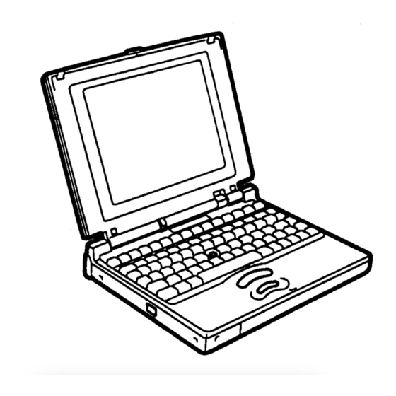
- Page 3 The T3400/T3400CT Personal Computer is shown in Figure 1-1. T3400/T3400CT system configuration is shown in Figure 1-2. Figure 1-1 T3400/T3400CT Personal Computer Figure 1-2 T3400/T3400CT System Unit Configuration T3400/T3400CT Maintenance Manual...
-
Page 4: System Unit Block Diagram
System Unit Block Diagram Figure 1-3 is a block diagram of the T3400/T3400CT system unit. Figure 1-3 T3400/T3400CT System Board Block Diagram T3400/T3400CT Maintenance Manual... - Page 5 The T3400/T3400CT system board includes the following major components: i486SX-33 CPU Super Integration (SI) T9901 Gate Array (GA), which houses the following: • Two Direct Memory Access Controllers (DMAC): 82C37 • Two Programmable Interrupt Controllers (PIC): 82C59 • One Programmable Interval Timer (PIT): 82C54 •...
- Page 6 - Toshiba Special Register • Processing Speed Controller • Data Bus Change Controller • Data Latch PCMCIA Controller GA This GA has the following functions: • Memory Card Controller - PCMCIA IC Card Controller - Toshiba Modem Card Controller T3400/T3400CT Maintenance Manual...
- Page 7 2,000 1,000 Formatted 1,311 Number of heads Number of cylinders Access time (ms) Track to track Average Head settling time Recording track density (tpi) Data transfer rate (Kbps) Rotation speed (rpm) Recording method Modified Frequency Modulation (MFM) T3400/T3400CT Maintenance Manual...
-
Page 8: Inch Hard Disk Drive
The HDD is a random-access, non-volatile storage device. It has a non-removable 2.5-inch magnetic disk and mini-Winchester type magnetic heads. The T3400/T3400CT supports a 120 MB HDD. The HDD is shown in Figure 1-5. Specifications for the HDD are provided in Table 1-2. - Page 9 The 82-key (USA) or 84-key (European) keyboard is mounted on the system unit. The keyboard is connected to the KBC on the system board via a 19-pin flat cable. The keyboard is shown in Figure 1-6. See Appendix F for optional configurations. Figure 1-6 Keyboard T3400/T3400CT Maintenance Manual...
- Page 10 1.6.1 Monochrome LCD Module The T3400 monochrome LCD supports 640 x 480 pixels with a video controller and 64 levels of gray. The video controller includes the functions of the VGA and SVGA. The LCD receives vertical and horizontal synchronizing signals, 8-bit data signals (4-bit upper block data signal and 4-bit lower block data signal), and shift clock for data transmis- sion.
- Page 11 The FL inverter board supplies the high-frequency current needed to illuminate the FL. Specifications for the FL inverter board are provided in Table 1-4. Table 1-4 Monochrome FL Inverter Board Specifications Item Specifications Input Voltage (VDC) Power Voltage (VAC) 1,100 (r.m.s) Output Current (mA) 5.0 (r.m.s) Frequency (KHz) 1-11 T3400/T3400CT Maintenance Manual...
-
Page 12: Tft Color Lcd
Table 1-5 TFT Color LCD Specifications Item Specifications Number of dots (dots) 640 x 480 Dot pitch (mm) 0.249 (W) x 0.249 (H) Display area (mm) 159.36 (W) x 119.52 (H) Contrast 55:1 (minimum) FL current (mA) FL frequency (KHz) 1-12 T3400/T3400CT Maintenance Manual... - Page 13 The FL inverter board supplies high-frequency current to light the LCD Fluorescent Lamp. Specifications for the FL inverter are provided in Table 1-6. Table 1-6 FL Inverter Board Specifications Item Specifications Input Voltage (VDC) Power Output Voltage (VAC) 1,100 (r.m.s) Current (mA) Frequency (KHz) 1-13 T3400/T3400CT Maintenance Manual...
-
Page 14: Power Supply
Table 1-7 Power Supply Output Ratings Regulation Maximum Use for Name voltage tolerance current Ripple (mA) (mV) System logic, FDD, HDD, ±5 3,500 Display DSPV +10.8/+15 ±5 RS-232-C Flash ROM ±5 RAM, CPU +3.3 ±5 1,170 RS-232C 1-14 T3400/T3400CT Maintenance Manual... - Page 15 Batteries The T3400/T3400CT has three types of batteries: Main battery pack Backup battery RTC battery Battery specifications are provided in Table 1-8. Table 1-8 Battery Specifications Battery name Material Output voltage Capacity Main battery pack Lithium-Ion 10.8 V 3,000 mAH...
- Page 16 AC adapter > Main battery pack > Backup battery The backup battery is charged by the main battery pack or AC adapter when the system is powered on. Table 1-10 shows the charging time and data preservation period of the backup battery. 1-16 T3400/T3400CT Maintenance Manual...
- Page 17 Table 1-11 shows the charging time and data preservation period of the RTC battery. Table 1-11 RTC Battery Charging/Data Preservation Time RTC Battery Time Charging Time Power On 48 Hours Power Off Doesn’t charge Data preservation period (full charge) 1 month 1-17 T3400/T3400CT Maintenance Manual...
-
Page 18: Troubleshooting
Diagnostics Disk operations are described in Chapter 3 and detailed replacement procedures are given in Chapter 4. The following tools are necessary for troubleshooting: 1. T3400/T3400CT Diagnostics Disk Phillips-head screwdriver (2 mm) Toshiba MS-DOS system disk(s) 2DD or 2HD formatted work disk for FDD testing... -
Page 19: Troubleshooting Flowchart
(F31PRT), then turn the POWER switch on. The computer will override the password function by erasing the current password. Verify with the customer that Toshiba MS-DOS is installed on the hard disk. Non- Toshiba operating systems can cause the computer to malfunction. - Page 20 Figure 2-1 Troubleshooting Flowchart T3400/T3400CT Maintenance Manual...
- Page 21 If an error is detected on the floppy disk test, perform the floppy disk drive troubleshooting procedures in Section 2.5. If an error is detected on the hard disk test, perform the hard disk drive troubleshooting procedures in Section 2.6. T3400/T3400CT Maintenance Manual...
-
Page 22: Power Supply Troubleshooting
Check 2 If the DC IN icon flashes green when the AC adapter is connected, its voltage output is abnormal. Connect a new AC adapter and turn the T3400/T3400CT on again to verify the indicator condition. Check 3 The battery pack may be malfunctioning. - Page 23 If the battery terminal is clean and not bent, go to Check 4. Check 4 Connect a new AC adapter. If the indicator does not glow, go to Check 5. Check 5 Install a new battery pack. If the indicator does not glow, go to Procedure 3. T3400/T3400CT Maintenance Manual...
- Page 24 Connection and Replacement Check The power supply board is interfaced to the system board through the joint board, which may be disconnected or damaged. Disassemble the T3400/T3400CT following the steps described in Chapter 4, Replacement Procedures, and perform the following checks.
-
Page 25: System Board Troubleshooting
The procedures provided are: Procedure 1: Message Check Procedure 2: Printer Port LED Check on Boot Mode Procedure 3: Printer Port LED Check on Resume Mode Procedure 4: Diagnostic Test Program Execution Check Procedure 5: Replacement Check T3400/T3400CT Maintenance Manual... - Page 26 If an error message is shown on the display, perform Check 1. If there is no error message, go to Procedure 2. If Toshiba MS-DOS is properly loaded, go to Procedure 3. Check 1 If one of the following error messages is displayed on the screen, press the F1 key as instructed.
- Page 27 (17) PIC #2 ERROR (18) KEYBOARD ERROR (19) KBC ERROR (20) HDC ERROR (21) HDD #0 ERROR (22) HDD #1 ERROR (23) NO FDD ERROR (24) FDD ERROR (25) TIMER INTERRUPT ERROR (26) RTC UPDATE ERROR 2-10 T3400/T3400CT Maintenance Manual...
- Page 28 PRT and the computer to boot mode. Figure 2-2 Printer Port LED To use the printer port LED, follow these steps: Turn on the T3400/T3400CT power, then set to boot mode. Turn off the power. Plug the printer port LED into the PRT/FDD connector.
- Page 29 ADDRESS = XXXXXXXXH READ DATA = XXXXXXXXH WRITE DATA = XXXXXXXXH EXTENDED MEMORY PARITY ERROR ADDRESS = XXXX0000H - XXXXFFFFH DMA page register test DMA PAGE REGISTER ERROR READ DATA = XXH WRITE DATA = XXH 2-12 T3400/T3400CT Maintenance Manual...
- Page 30 Section 2.7. Check 3 If error code 5Ah is displayed, go to the HDD Troubleshooting Procedures in Section 2.6. Check 4 If error code 60h is displayed, go to the FDD Troubleshooting Procedures in Section 2.5. 2-13 T3400/T3400CT Maintenance Manual...
- Page 31 PRT and the computer to resume mode. To use the printer port LED, follow these steps: Turn on the T3400/T3400CT power, then set to resume mode. Turn off the power. Plug the printer port LED into the PRT/FDD connector.
- Page 32 If an error is detected during the tests, go to Procedure 5. Procedure 5 Replacement Check The system board may be damaged. Disassemble the T3400/T3400CT following the steps described in Chapter 4, Replacement Procedures, and perform the following check: Check 1 Replace the system board.
- Page 33 FDD head cleaning is one option available in the Diagnostic Program. Detailed procedures are given in Chapter 3, Tests and Diagnostics. After loading Toshiba MS-DOS, run the Diagnostic Program and then clean the FDD heads using the cleaning kit. If the FDD does not function properly after cleaning, go to Procedure If the test program in Procedure 3 cannot be executed, go to Procedure 2.
- Page 34 Procedure 3 Diagnostic Test Program Execution Check The FDD Diagnostic Test program is stored on the T3400/T3400CT Diagnostics Disk. After loading Toshiba MS-DOS, run the diagnostic program. Refer to Chapter 3, Tests and Diag- nostics, for more information about the diagnostics test procedures.
- Page 35 The FDD or FDD cable may be defective. Replace the FDD and cable. If the FDD is still not functioning properly, perform Check 3. Check 3 Replace the system board following the steps in Chapter 4, Replacement Proce- dures. 2-18 T3400/T3400CT Maintenance Manual...
-
Page 36: Hard Disk Drive Troubleshooting
Procedure 1 Partition Check Insert the Toshiba MS-DOS system disk and turn on the computer, then perform the follow- ing checks: Type C: and press Enter . Go to Check 2 if the drive will not change to C. Go to Check 1 Procedure 2 if the drive changes to C. - Page 37 Non-System disk or disk error Replace and press any key Check 3 Using the Toshiba MS-DOS system disk, install a system program on the hard disk using the SYS command. If the following message appears on the display, the system program has been transferred to the HDD.
- Page 38 HDD. If the following message appears on the display, the HDD is formatted. Format complete If any other error message appears on the display, refer to the Toshiba MS-DOS Manual for more information and perform Check 2. Check 2 Using the T3400/T3400CT Diagnostic Disk, format the HDD with a low-level format option.
- Page 39 Procedure 4 Diagnostic Test Program Execution Check The HDD test program is stored on the T3400/T3400CT Diagnostics Disk. Perform all of the HDD tests in the Hard Disk Drive Test. Refer to Chapter 3, Tests and Diagnostics, for more information about the HDD test program.
-
Page 40: Keyboard Troubleshooting
Connector and Replacement Check The keyboard is connected to the system board by a 19-pin flat cable. This cable may be disconnected or damaged. Disassemble the T3400/T3400CT as described in Chapter 4, Replacement Procedures, and perform the following checks: Check 1 Make sure the keyboard cable is not damaged and is connected to the system board. -
Page 41: Display Troubleshooting
Procedure 2 Diagnostic Test Program Execution Check The Display Test program is stored on the T3400/T3400CT Diagnostic Disk. This program checks the display controller on the system board. After loading Toshiba MS-DOS, run the Diagnostic Program. Refer to Chapter 3, Tests and Diagnostics, for details. - Page 42 If some screen functions do not operate properly, perform Check 3. If the FL remains illuminated when the display is closed, perform Check 4. Check 1 Replace the FL (T3400) or FL unit (T3400CT) and test the display. If the prob- lem persists, perform Check 2. Check 2 Replace the FL inverter board and test the display.
- Page 43 Replace the LED board and test the display. If the problem still exists, perform Check 5. Check 5 Replace the display cable and test the display. If the problem persists, perform Check 6. Check 6 The system board may be damaged. Replace the system board. 2-26 T3400/T3400CT Maintenance Manual...
-
Page 44: The Diagnostic Test
REAL TIMER TEST PCMCIA TEST The following equipment is needed to perform some test programs. T3400/T3400CT Diagnostics Disk (all tests) Formatted working disk for the floppy disk drive test (all tests) 3.5-inch 2HD/2DD disk for internal 3.5-inch FDD 5.25-inch 2D disk for external 5.25-inch FDD... - Page 45 Executing the DiagnosticTest Toshiba MS-DOS is required to run the T3400/T3400C DIAGNOSTICS PROGRAM. NOTE: Diagnostics cannot be run with expanded memory managers such as EMM386 or Quarterdeck QEMM in memory. Attempting to run diagnostics with either program loaded will cause the following message to display: Cannot execute in a virtual 8086 mode.
- Page 46 The following menu appears: TOSHIBA personal computer T3400XX DIAGNOSTICS version X.XX (c) copyright TOSHIBA Corp. 19XX DIAGNOSTICS MENU : 1 - DIAGNOSTIC TEST 2 - HARD DISK FORMAT 4 - HEAD CLEANING 5 - LOG UTILITIES 6 - RUNNING TEST...
- Page 47 To select the DIAGNOSTIC TEST option from the DIAGNOSTICS MENU, set the highlight bar to 1 , and press Enter . The following screen appears: TOSHIBA personal computer T3400XX DIAGNOSTICS version X.XX (c) copyright TOSHIBA Corp. 19XX DIAGNOSTIC TEST MENU : 1 - SYSTEM TEST...
- Page 48 Selecting NO for ERROR STOP keeps a test running even if an error is found. Table 3-1 in section 3.3 describes each subtest menu test function; Table 3-3 in section 3.14 lists codes and status for each error. T3400, T3400CT...
-
Page 49: Subtest Names
320*200 Graphics display 640*200 Graphics display 640*350/400/480 Graphics display Display page “H” pattern display/Border color LED/DAC pallet 64 color display FDD to VRAM Sequential read Sequential read/write Random address/data Write specified address Read specified address PRINTER Ripple pattern Function Wraparound T3400, T3400CT... - Page 50 Address uniqueness Random address/data Cross talk & peak shift Write/read/compare (CE) Write specified address Read specified address ECC circuit Sequential write W-R-C specified address REAL TIMER Real time Backup memory Real time carry PCMCIA I/O card test (PCMCIA) T3400, T3400CT...
-
Page 51: System Test
Table 3-2 Hardware Bit Status H/W status Reserved — — CPU clock speed 16.5 MHz 33 MHz Media type FDD type 1.6 MB 2 MB Reserved — — Drive A/B Ext. = A Ext. = B External FDD Internal FDD T3400, T3400CT... - Page 52 ROM-BIOS = V1.00 : OK V1.10 ROM(BOOT) = V1.00 : OK V1.00 KBC Version = V1.26 : NG V1.00 PS Micom Version = V1.35 : OK V1.35 Reference data Current data T3400, T3400CT...
-
Page 53: Memory Test
Subtest 04 Protected mode This subtest writes constant data and address data to extended memory (maxi- mum address 100000h) then reads new data and compares the result with original data. Constant data is FFh, AAh, 55h, and 00h. 3-10 T3400, T3400CT... - Page 54 (‘7000’:’Program’ size to ‘7000’:=7FFF’ (32 KB)) to check hit-miss ratio (on/off status). One test takes 3 seconds. Number of miss hit < Number of hit → OK Number of miss hit > Number of hit → Fail 3-11 T3400, T3400CT...
-
Page 55: Keyboard Test
“*” character. Holding a key down enables the auto-repeat function which causes the key display character to blink. KEYBOARD TEST IN PROGRESS 301000 PrtSc [Alt] + [SysReq] Pause [Ctrl]+[Break] to test end If test OK, Press [Del] then [Enter] Key 3-12 T3400, T3400CT... - Page 56 Pointing Stick Check NOTE: To execute the pointing stick check, mouse driver software must be in- stalled in the system. This subtest checks pointing stick functions. If no error is detected, it returns to the subtest menu. 3-13 T3400, T3400CT...
-
Page 57: Display Test
NEXT LINE SHOWS BLINKING DISPLAY BBBBBBBBBBBBBBBBBBBBBBBBBBBBBB 00 08 ; BLACK 01 09 ; BLUE 04 0C ; RED 05 0D ; MAGENTA 02 0A ; GREEN 03 0B ; CYAN 06 0E ; YELLOW 07 0F ; WHITE PRESS [Enter] KEY 3-14 T3400, T3400CT... - Page 58 Character Set In this subtest, the character set (address 00h to FFh) is displayed in the 40*25 character mode as shown below. Press [Enter] KEY To exit to the DISPLAY TEST menu, press Ctrl + Break . 3-15 T3400, T3400CT...
- Page 59 4 and D. One example is shown below: 320*200 GRAPHICS DISPLAY COLOR SET X : [X] GREEN BROWN CYAN MAGENTA WHITE PRESS [ENTER] KEY Pressing Enter toggles between tests. To exit to the DISPLAY TEST menu, press Ctrl + Break . 3-16 T3400, T3400CT...
- Page 60 640x480 dot graphics mode 10, 74, 12 as shown below: 640*XXX GRAPHICS DISPLAY EVEN DOTS ODD DOTS ALL DOTS DRIVEN DRIVEN DRIVEN PRESS [Enter] KEY Press Enter to change displayed image size. To exit to the DISPLAY TEST menu, press Ctrl + Break. 3-17 T3400, T3400CT...
- Page 61 HHHHHHHHHHHHHHHHHHHHHHHHHHHHHHHHHHHHHHHHHHHHHHHHHH Pressing Enter displays the following message: Setting the color CRT (1:yes/2:no) If an external CRT is connected to the T3400/T3400CT, choose 1 to display the following message: [Border color test (press [Enter] key 7 times)] Press Enter to execute the border color test.
- Page 62 64 shades of red, green, and blue succes- sively, and the last three display 64 shades of red, green and blue. Press Enter to change the display. Press Ctrl + Break to exit. 3-19 T3400, T3400CT...
-
Page 63: Floppy Disk Test
The fourth indicates the head, and the last two indicate the sector being tested. The first digit in the STATUS number indicates the drive being tested and the last two indicate the error status code as explained in Table 3-3. 3-20 T3400, T3400CT... - Page 64 01. Data is then read and compared to the original data. Subtest 04 Write Specified Address This subtest writes specified data to a specified track, head, and address. Subtest 05 Read Specified Address This subtest reads data from a specified track, head, and address. 3-21 T3400, T3400CT...
-
Page 65: Printer Test
= XXXXh channel#3 = XXXXh Select the channel number (1-3) ? The printer I/O port address is specified by the XXXXh number. The T3400/T3400CT supports three printer channels. Select the appropriate printer channel number, and press Enter to execute a subtest. - Page 66 NOTE: To execute this subtest, a printer wraparound connector must be connected to the computer printer port. The printer wraparound connector (34M741986G01) wiring diagram is shown in Appendix G. This subtest checks output and bidirectional modes of the data control and status lines through the printer wraparound connector. 3-23 T3400, T3400CT...
-
Page 67: Async Test
NOTE: To execute this subtest, an RS-232C cable (9-pin to 9-pin) must be con- nected to boards 1 and 2. The RS-232C direct cable wiring diagram is shown in Appendix G. This subtest checks the data send/receive function through the RS-232C direct cable. 3-24 T3400, T3400CT... - Page 68 Select the baud rate and mode for the card modem and press Enter to execute the subtest. Subtest 06 Interrupt Test This subtest checks the Interrupt Request Level of IRQ 4, 3 and 5 from the send side. 3-25 T3400, T3400CT...
-
Page 69: Hard Disk Test
CAUTION: The contents of the hard disk will be erased when subtest 02, 03, 04, 05, 06, 08, 09, or 10 is executed. Before running the test, transfer the contents of the hard disk to a floppy disk(s). This can be done with the Toshiba MS-DOS BACKUP command. - Page 70 • Forward sequential • Reverse sequential • Random Subtest 03 Random Address/Data This subtest writes random data to random addresses on the HDD cylinder, head, and sector. This data is then read and compared to the original data. 3-27 T3400, T3400CT...
-
Page 71: Subtest 04
Sequential write This subtest writes specified 2-byte data to all cylinders. Subtest 10 W-R-C specified address This subtest writes data to a specified cylinder and head, then reads the data and compares it to the original data. 3-28 T3400, T3400CT... -
Page 72: Real Timer Test
Writes 1-bit of “off” data to address FEh through 7Fh Writes the data pattern AAh through 55h to the RTC 50-byte memory (address 0Eh to 3Fh) The subtest then reads and compares this data with original data. To exit, press Ctrl + Break . 3-29 T3400, T3400CT... - Page 73 Current date : 12-31-1992 Current time : 23:59:58 Pressing Enter displays the following Current date : 01-01-1993 Current time : 00:00:00 PRESS [Enter] KEY TO EXIT TEST Press Ctrl + Break to exit. 3-30 T3400, T3400CT...
- Page 74 Contents 00001 Address line 00001 REG#, CE#1, CE#2 nn=A0, 90, 80, 00 00002 Data line ww=write data, rr=read data 00003 –– –– Speaker line 00004 40, 80 Wait line (40<xx<80) 00005 Other lines (BSY#, BVD1) nn=21, 00 3-31 T3400, T3400CT...
-
Page 75: Error Code And Error Status Names
Media Removed DMA Overrun Error DMA Boundary Error CRC Error FDC Error Seek Error FDD Not Drive Error Time Out Error Write Buffer Error Printer Time Out Fault Select Line Out Of Paper Power Off Busy Line 3-32 T3400, T3400CT... - Page 76 Undefined Error Write Fault Status Error Access Time Out Error PCMCIA Address Line Error REG# Line Error CE#1 Line Error CE#2 Line Error DATA Line Error WAIT Line Error BSY# Line Error BVD1 Line Error No PCMCIA 3-33 T3400, T3400CT...
-
Page 77: Hard Disk Test Detail Status
“1” --- Drive is ready for data transfer. CORR “0” --- Other (Corrected data) “1” --- Correctable data error was corrected. “0” --- Other (Index) “1” --- Index is sensed. “0” --- Other (Error) “1” --- The previous command was terminated with some error. 3-34 T3400, T3400CT... - Page 78 “1” Illegal command error or a drive status error occurred. TK00 “0” The hard disk found track 0 during a recalibrate command. (Track 0) “1” The hard disk could not find track 0 during a recalibrate command. —— Not used. 3-35 T3400, T3400CT...
-
Page 79: Hard Disk Format
CAUTION: The hard disk will be erased when this program is executed. Before ex- ecuting, transfer hard disk contents onto a backup system. This can be done with the Toshiba MS-DOS BACKUP command. See the Toshiba MS-DOS manual for details on using the BACKUP command. - Page 80 CAUTION: The hard disk will be erased when this program is executed. Before executing, transfer the contents of the hard disk onto a backup system. This can be done with the Toshiba MS-DOS BACKUP command. See the Toshiba MS-DOS manual for details on using the BACKUP command.
- Page 81 Item (d) above, or identified as bad tracks in the Track Verification func- tion described in Item (f) below. Track Verification A check is made of all tracks, and if an ECC, ECC-correctable, or record- not-found track error is detected, the track is formatted as a bad track . 3-38 T3400, T3400CT...
- Page 82 Press Enter to return to the Hard Disk Format menu. NOTE: After the HDD has been formatted, execute the Toshiba MS-DOS FDISK command to partition the HDD. Next, execute the Toshiba MS-DOS FORMAT com- mand. Refer to the Toshiba MS-DOS manual for more information about using these commands. 3-39...
-
Page 83: Head Cleaning
Remove the Diagnostics Disk from the FDD, insert the cleaning disk, and press Enter. When the cleaning start message appears, FDD head cleaning has begun. The display returns to the DIAGNOSTIC MENU when the program is completed. 3-40 T3400, T3400CT... -
Page 84: Pass Count
001 FDD 01 0000 180 00001 00 00 FDD - TIME OUT ERROR Address Error status Pass count HDC status Subtest number Read data Test name Write data Error count Error status name [[1:Next,2:Prev,3:Exit,4:Clear,5:Print,6:FD Log Read,7:FD Log Write]] 3-41 T3400, T3400CT... - Page 85 6 reads log information from a floppy disk. 7 writes log information to a floppy disk. In the case of “error retry OK,” a capital “R” will be placed at the beginning of the error status, but not added to the error count. 3-42 T3400, T3400CT...
-
Page 86: Running Test
HDD test (subtest numbers 01, 05 Real timer test (subtest number 02) Printer test (subtest number 03) Async test (subtest number 01) The system detects the number of floppy disk drives connected to the T3400/T3400CT for the FDD test. 3.19.2 Operations CAUTION: Do not forget to load a work disk in the FDD. - Page 87 Select Yes or No and press Enter to display the following message: Mount the work disk(s) on the drive(s), then press [Enter] key. [Warning] : The contents of the disk(s), will be destroyed.] This program is executed continuously. To terminate the program, press Ctrl + Break. 3-44 T3400, T3400CT...
-
Page 88: Floppy Disk Drive Utilities
FDD and HDD. FORMAT NOTE: This program is only for testing a floppy disk drive. The option is different from the Toshiba MS-DOS FORMAT command. This program can format a 5.25-inch or 3.5-inch floppy disk in the following formats: 2D: Double-sided, double-density, 48/67.5 TPI, MFM mode, 512 bytes, 9 sectors/track. - Page 89 Select COPY to display the following message: FLOPPY DISK FORMAT & COPY : VX.XX Type select (0:2DD-2DD,1:2D-2D,2:2D-2HD,3:2HD-2HD) ? Select a media/drive type number to display a message similar to the one below: Insert source disk into drive A: Press any key when ready. 3-46 T3400, T3400CT...
- Page 90 Insert a source disk and press any key and the following message will appear: —— Max. address —— [Track ] = 0079 [ Head ] = 01 [Sector] = 09 Track number ?? Set a track number to dump. The system will access the disk and dump a list. 3-47 T3400, T3400CT...
-
Page 91: System Configuration
* - 1 ASYNC ADAPTER * - 1 HARD DISK DRIVE(S) * - 1 PRINTER ADAPTER * - XXXXXKB EXTENDED MEMORY * - PS MICOM VERSION = VX.XX Press [Enter] Key Press Enter to return to the DIAGNOSTIC MENU. 3-48 T3400, T3400CT... - Page 92 Total (b) Base Extended Memory Shadow BIOS ROM Display Display Adapter LCD Display Mode LCD Gray Scale Level (T3400 only) LCD Display Colors (T3400CT only) Power On Display (T3400CT only) COM/PCMCIA/FDD/PRT Serial Port PC Card Slot Ext. FDD/PRT Printer Port Type...
-
Page 93: Accessing The Setup Program
Esc: Exit without saving, Home: Set default values, End: Save changes and Exit NOTE: LCD Gray Scale Level does not appear on the T3400CT screen. Power On Display does not appear on the T3400. Panel Power On/Off appears when either computer is in Resume mode. - Page 94 This field displays the amount of extended memory available. These values may not be changed by the user. Shadow BIOS ROM The SETUP program displays 128 KB of RAM reserved for Shadow BIOS ROM. These values may not be changed by the user. 3-51 T3400, T3400CT...
- Page 95 LCD Gray Scale Level (T3400 only) Use this option, which appears in SETUP and the Pop-up Window, to switch between normal and reverse video on the T3400. It does not appear on the T3400CT. The options are: Normal 64 levels Displays black text on white background with 64 shades of gray.
- Page 96 (PCMCIA default) Not Used (Disables port) If the Serial Port COM level is set to the same level as the Toshiba card modem, the card modem COM level is automatically reset to Not Used. PC Card Slot Use this option to select PC Card slot usage: PCMCIA Choose this selection when a PCMCIA card is installed.
- Page 97 Activates bi-directional operation. Hard Disk This option enables or disables the HDD. 120 MB The hard disk can be accessed. Disk capacity is automatically displayed and cannot be changed. No Drive The hard disk cannot be accessed. 3-54 T3400, T3400CT...
- Page 98 NOTE: AutoResume does not work with the enhanced mode of Microsoft Win- dows unless WRESUME driver is loaded. Refer to Power-On Modes in Chapter 2 of the T3400 Reference Manual for additional information. CPU Cache Use this feature to enable or disable the CPU cache.
- Page 99 This option is used to select Full Power, Low Power, or User Setting of the BATTERY SAVE OPTION. Full Power The following shows full power settings. CPU Sleep Mode Disabled Display Auto Off = Disabled (T3400) 30 Min.(T3400CT) HDD Auto Off Disabled System Auto Off Disabled LCD Brightness...
- Page 100 HDD → FDD Computer looks for files to boot first on the HDD and next on the FDD. Reverse the order by holding down the F10 key while the computer is booting. This procedure does not affect the setting. 3-57 T3400, T3400CT...
- Page 101 Use this option to disable or set the duration of the display automatic power- off function. This function causes the computer to turn the LCD panel illumination off if no entry is made for the set period of time. 3-58 T3400, T3400CT...
- Page 102 Duration xx can be set to 10, 20, 30, 40, 50 or 60 minutes. LCD Brightness Use this option to set the LCD brightness level. Bright Full brightness for maximum visibility. Semi-bright Less than full brightness for saving power. 3-59 T3400, T3400CT...
- Page 103 RTC Battery, Backup battery Accupoint Control Button System Board Power Supply Board FL Inverter Board Monochrome LCD Display (T3400) TFT Color LCD Display (T3400CT) FL Unit Before Beginning Look over the procedures in this section before disassembling the computer. Become familiar with disassembly and reassembly steps.
- Page 104 The computer has many sharp edges and corners, be careful and avoid injury. Make sure the computer is functioning properly by performing the appropriate test on the FRU installed. NOTE: The illustrations in Chapter 4 are based on the appearance of the T3400, unless otherwise noted. Disassembly Procedures...
- Page 105 Jeweler’s screwdriver. Tweezers to lift out screws. ESD mats for the floor and the table. ESD wrist strap or heel grounder. Anti-static carpeting or flooring. Air ionizers in highly static-sensitive areas. LCD support block composed of anti-static foam. T3400, T3400CT...
-
Page 106: The Battery Pack
With your left hand, slip your fingers into the gap and pull the battery pack to the left until it stops (about 1 centimeter or 1/2 inch). Grasp the left end of the battery pack and lift up to remove (Figure 4-2). Figure 4-2 Lifting Out the Battery Pack T3400, T3400CT... - Page 107 Gently press down on the center of the battery pack and at the same time push it to the right. Slight resistance will be felt when the battery is nearly seated. Press in carefully until it clicks into place, then lock the battery lock (Figure 4-1). T3400, T3400CT...
- Page 108 Slide a fingernail or other thin object under the notch on the cover and rotate up to remove. Two latches hold the cover in place on the side away from the screws (Figure 4-3). Figure 4-3 Removing the Memory Module Socket Cover T3400, T3400CT...
- Page 109 The side of the module away from the connector edge will spring up (Figure 4-4). Figure 4-4 Removing the Memory Module CAUTION: DO NOT touch the connector edge of the memory card. Debris or oil may cause memory access problems. T3400, T3400CT...
- Page 110 (Figure 4-4). Fit the socket cover latches into place and seat the cover (Figure 4-3). Secure the two M2.5x4 screws (Figure 4-3). Install the battery pack as described in section 4.2. T3400, T3400CT...
- Page 111 Remove the battery pack as described in section 4.2. Snap off the PCMCIA slot cover (Figure 4-6). Press the eject button to pop the card out slightly (Figure 4-6). Grasp the card edges and remove. Figure 4-6 Removing the PCMCIA Card T3400, T3400CT...
- Page 112 Some resistance will be felt when the card is almost seated. Press gently to assure firm connection, but do not force. The eject button will pop out when the card is fully seated (Figure 4-7). Figure 4-7 Installing the Optional PCMCIA Card Install the battery pack as described in section 4.2. 4-10 T3400, T3400CT...
-
Page 113: Top Cover
Remove seven M2.5x8 silver screws from the bottom of the computer and two M2.5x4 screws from the battery seating area. These screws secure the top cover to the bottom cover (Figure 4-8). Figure 4-8 Removing the Bottom Cover Screws 4-11 T3400, T3400CT... - Page 114 (Figure 4-10). Disconnect the AccuPoint cable from PJ503, keyboard cable from PJ8, LED cable from PJ16, and display cable from PJ10 (Figure 4-10). Figure 4-10 Disconnecting the Connectors Lift off the top cover. 4-12 T3400, T3400CT...
- Page 115 Close the computer, and secure the top cover with seven M2.5x8 silver screws and two M2.5x4 screws (Figure 4-8). Replace the optional PCMCIA card, optional memory card, and battery pack as described in sections 4.4 through 4.2. 4-13 T3400, T3400CT...
- Page 116 Remove one M2.5x6 brass screw securing the HDD bracket to the bottom cover (Figure 4-11). Disconnect the HDD flexible cable from PJ5 on the system board. (Figure 4-11). Lift out the HDD (Figure 4-11). Figure 4-11 Removing the HDD and Bracket 4-14 T3400, T3400CT...
- Page 117 Slip the flexible cable out of three latches on the HDD bracket to remove the HDD. Figure 4-12 Removing the HDD Flexible Cable Remove four M3x4 flat-head screws securing the bracket to the HDD (Figure 4- 13). Remove the bracket (Figure 4-13). Figure 4-13 Removing the HDD 4-15 T3400, T3400CT...
- Page 118 Connect the flexible cable to PJ5 on the system board (Figure 4-11). Secure the HDD with one M2.5x6 brass screw (Figure 4-11). Replace the top cover, optional PCMCIA card, optional memory card, and battery pack as described in sections 4.5 through 4.2. 4-16 T3400, T3400CT...
- Page 119 Disconnect the backup battery cable from PJ1 on the power supply board, lift the backup battery out of the bottom cover, and remove the clear plastic insulator (Figure 4-14). Figure 4-14 Removing the RTC and Backup Batteries 4-17 T3400, T3400CT...
- Page 120 Route the RTC battery cable under the clear plastic insulator, then connect the cable to PJ2 on the system board (Figure 4-14). Replace the top cover, optional PCMCIA card, optional memory card, and battery pack as described in sections 4.5 through 4.2. 4-18 T3400, T3400CT...
- Page 121 Disconnect the control button cable from PJ801 on the power supply/system joint board (Figure 4-15). Slide the control button and cable free of latches on the bottom cover and lift out to remove (Figure 4-15). Figure 4-15 Removing the AccuPoint Control Button 4-19 T3400, T3400CT...
- Page 122 Slide the control button and cable under the latches on the bottom cover (Figure 4-15). Connect the control button cable to PJ801 on the power supply/system joint board (Figure 4-15). Replace the top cover, optional PCMCIA card, optional memory card, and battery pack as described in sections 4.5 through 4.2. 4-20 T3400, T3400CT...
-
Page 123: System Board
NOTE: Be careful with the PCMCIA card eject button, it may be necessary to open the PCMCIA slot cover for the button to clear the bottom cover. Be sure to ease the board carefully from its guide pins. Figure 4-16 Removing the System Board 4-21 T3400, T3400CT... - Page 124 Secure the system board to the bottom cover with one M2x6 screw. Replace the RTC and backup batteries, hard disk drive, top cover, optional PCMCIA card, optional memory card, and battery pack as described in sections 4.7 through 4.2. 4-22 T3400, T3400CT...
-
Page 125: Power Supply Board
4.2 through 4.9. Lift out the power supply board, being careful to clear the plastic light conduc- tor for the battery LED indicator (Figure 4-17). Figure 4-17 Removing the Power Supply Board 4-23 T3400, T3400CT... - Page 126 LED indicator (Figure 4-17). Replace the system board, AccuPoint control button, RTC and backup batteries, hard disk drive, top cover, optional PCMCIA card, optional memory card, and battery pack as described in sections 4.9 through 4.2. 4-24 T3400, T3400CT...
- Page 127 From the top (keyboard) side, use a thin object to pry up the left and right sides of the plastic panel slightly, then pry open and release the other latches, starting near the ends and working toward the center (Figure 4-19). Figure 4-19 Unlatching the Plastic Panel 4-25 T3400, T3400CT...
- Page 128 Secure three M2.5x6 brass screws at the front of the keyboard (Figure 4-20). Seat the plastic panel and press firmly to secure the latches (Figure 4-19). Replace the top cover, optional PCMCIA card, optional memory card, and battery pack as described in sections 4.5 through 4.2. 4-26 T3400, T3400CT...
- Page 129 Remove the M2.5x4 brass screw securing the LED board (Figure 4-21). Using a thin object to release the two latches on the top cover, pull up gently on the LED holder and remove it. Lift out the LED board. Figure 4-21 Removing the LED Board 4-27 T3400, T3400CT...
- Page 130 Seat the LED holder on the LED board and press gently to secure the latches (Figure 4-21). Secure the M2.5x4 brass screw holding the LED board and LED holder (Figure 4-21). Replace the top cover, optional PCMCIA card, optional memory card, and battery pack as described in sections 4.5 through 4.2. 4-28 T3400, T3400CT...
-
Page 131: Display Mask
Continue around the display cover to release two more latches at the top, four latches on each side and five latches at the bottom (Figure 4-22). Figure 4-22 Removing the Display Mask 4-29 T3400, T3400CT... - Page 132 Secure two brass M2x6 screws at the top of the display cover and two brass M2.5x6 screws at the bottom (Figure 4-22). Replace the two rubber pads and two screw covers (Figure 4-22). Replace the battery pack as described in section 4.2. 4-30 T3400, T3400CT...
-
Page 133: Fl Inverter Board
Remove the battery pack and display mask as described in sections 4.2 and 4.13. Remove two brass M2x6 screws from the FL inverter board. Turn over the board and disconnect the FL inverter cable from CN1 and the FL cable from CN2. Figure 4-23 Removing the FL Inverter Board 4-31 T3400, T3400CT... - Page 134 Turn the board over and connect the FL inverter cable to CN1 and the FL cable to CN2 (Figure 4-23). Secure two brass M2x6 screws holding the the FL inverter board (Figure 4-23). Replace the display mask and battery pack as described in sections 4.13 and 4.2. 4-32 T3400, T3400CT...
- Page 135 Remove four brass M2x6 screws at each corner of the display module. The screw at the bottom right corner also secures the ground cable (Figure 4-24). Rotate the display panel out so that it lies flat on an ESD-protected surface (Figure 4-24). Figure 4-24 Removing the Display Module Screws 4-33 T3400, T3400CT...
- Page 136 Disconnect the display's flat cable from the display unit (Figure 4-25). Figure 4-25 Disconnection From the Display Unit Disconnect the other end of the flat cable from the computer's display cable (Figure 4-26). Figure 4-26 Disconnection From the Display Cable 4-34 T3400, T3400CT...
- Page 137 (Figure 4-24). NOTE: Secure the ground cable at the bottom right corner with one of the screws. Replace the FL inverter board, display mask, and battery pack as described in sections 4.14, 4.13, and 4.2. 4-35 T3400, T3400CT...
- Page 138 Remove the battery pack, display mask, FL inverter board, and display module as described in sections 4.2, 4.13, 4.14, and 4.15. Remove three brass M2x2 flathead screws securing the FL cover (Figure 4-27). Lift out the FL cover. Figure 4-27 Removing the FL Cover Screws 4-36 T3400, T3400CT...
- Page 139 Seat the FL (Figure 4-28). Seat the FL cover and secure it with three brass M2x2 flat-head screws (Figure 4-27). Replace the display module, FL inverter board, display mask, and battery pack as described in sections 4.15, 4.14, 4.13, and 4.2. 4-37 T3400, T3400CT...
- Page 140 (Figure 4-29). Note the ground and display cable routing, then rotate the display module out of the display cover from left to right (Figure 4-29). Figure 4-29 Removing the Display Module Screws 4-38 T3400, T3400CT...
- Page 141 (Figure 4-29). NOTE: Secure the ground cable at the bottom right corner with one of the screws. Replace the FL inverter board, display mask, and battery pack as described in sections 4.14, 4.13, and 4.2. 4-39 T3400, T3400CT...
- Page 142 4.2, 4.13, 4.14, and 4.17. Noting display cable routing, place the FL unit face down and remove four M2x4 silver screws (Figure 4-31). Lift the FL unit out of the frame. Figure 4-31 Removing the FL Unit Screws 4-40 T3400, T3400CT...
- Page 143 Noting display cable routing, press into underlying groove, then seat the FL unit in the frame and secure four M2x4 silver screws (Figure 4-31). Replace the display module, FL inverter board, display mask, and battery pack as described in sections 4.17, 4.14, 4.13, and 4.2. 4-41 T3400, T3400CT...
-
Page 144: Appendix A Handling The Lcd Module
Appendix A Handling the LCD Module Precautions for handling the T3400/T3400CT LCD module The LCD module can be easily damaged during assembly or disassembly. Observe the follow- ing precautions when handling: When installing the LCD module in the LCD cover, be sure to seat it so that it is properly aligned and maximum visibility of the display is maintained. - Page 145 Water or other liquids left on the surface for a long period can change the screen tint or stain the screen. Be sure to quickly wipe off any liquid. Do drop or strike the LCD module with a hard object, glass used in the panel could break or crack. T3400, T3400CT...
- Page 146 Do not expose the module to direct sunlight or strong ultraviolet rays for long periods. Do not store the module at temperatures below specifications. Cold can cause liquid crystals to freeze, lose their elasticity, or otherwise suffer damage. T3400, T3400CT...
- Page 147 If transporting the module, do not use packing materials that contain epoxy resin (amine) or silicon glue (alcohol or oxime). These materials can release gas that can damage panel polarization. T3400, T3400CT...
- Page 148 Appendix B Board Layout System Board Front View Figure B-1 Board Layout (Front) T3400, T3400CT...
- Page 149 System Board Back View Figure B-2 Board Layout (Back) T3400, T3400CT...
- Page 150 Table B-2 System Board ICs and Connectors (Back) Mark Number Name IC3 to IC10 System Memory IC14 Real Time Clock IC16 T9901 IC18 BIOS ROM IC 20 Keyboard Controller IC 22 PCMCIA Controller Gate Array IC 26, IC27 Video RAM Memory Module Connector T3400, T3400CT...
- Page 151 T3400, T3400CT...
-
Page 152: Appendix C Pin Assignments
Appendix C Pin Assignments C.1 PJ1 Memory Slot Connectors (72-Pin) Table C-1 Memory Slot Connector Pin Assignment (72-Pin) Signal Signal – MD16;100 MD00;100 MD17;100 MD01;100 – MD02;100 CAS0;010 MD03;100 CAS2;010 MD04;100 CAS3;010 MD05;100 CAS1;010 MD06;100 RAS0;010 MD07;100 RAS1;010 – – –... - Page 153 PJ2 RTC Connectors (3-Pin) Table C-2 RTC Connector Pin Assignment (3-Pin) Signal Signal RTCBAT – – – PJ3 PRT/FDD Connectors (for Printer) (25-Pin) Table C-3 PRT/FDD Connector (for Printer) Pin Assignment (25-Pin) Signal Signal STROB;000 AUTFD;000 PDB00;100 ERROR;000 PDB01;100 PINT;000 PDB02;100 SLIN;000 PDB03;100...
- Page 154 PJ4 External 3.5-Inch FDD Connectors (26-Pin) Table C-5 External 3.5-inch FDD Connector Pin Assignment (26-Pin) Signal Signal – IFSTEP;010 IFINDX;000 – – IFWDAT;010 IFDASL;010 – – IFWEN;010 DSKCHG;000 – – IFTRK0;000 IFRADY;000 – IFHMED;000 IFWPRO;000 IFAMON;010 – IFLOD1;010 IFRDAT;000 IFDIRC;010 –...
- Page 155 PJ5 Internal HDD Connectors (50-Pin) Table C-6 Internal HDD Connector Pin Assignment (50-Pin) Signal Signal RESET;000 – – IRQ14;100 SD07;100 IOCS16;000 SD08;100 SA01;100 SD06;100 IPSSEL;100 SD09;100 SA00;100 SD05;100 SA02;100 SD10;100 HDCS0;000 SD04;100 IHDCS1;000 SD11;100 HDDLED;000 SD03;100 – SD12;100 – SD02;100 –...
- Page 156 PJ8 KB I/F Connectors (19-Pin) Table C-8 KB I/F Connector Pin Assignment (19-Pin) Signal Signal KBOT00;001 KBRT7;100 KBOT01;010 KBOT03;010 KBOT02;010 KBOT04;010 KBRT0;100 KBOT05;010 KBRT1;100 KBOT06;010 KBRT2;100 KBOT07;010 KBRT3;100 KBOT08;010 KBRT4;100 KBOT09;010 KBRT5;100 KBOT10;010 KBRT6;100 T3400C, T3400CT...
- Page 157 PJ9 PC Card Slot Connectors (68-Pin) Table C-9 PC Card Slot Connector Pin Assignment (68-Pin) Signal Signal – – PCD03;100 PCCD1;000 PCD04;100 PCD11;100 PCD05;100 PCD12;100 PCD06;100 PCD13;100 PCD07;100 PCD14;100 PCCE1;000 PCD15;100 PCA10;100 PCCE2;000 PCOE;000 – PCA11;100 PCIOR;000 PCA09;100 PCIOW;000 PCA08;100 PCA17;100 PCA13;100 PCA18;100...
- Page 158 C.10 PJ10 LCD Connectors (40-Pin) Table C-10 LCD Connector Pin Assignment (40-Pin) Signal Signal DSPV – – DSPV – UD2;130 – – – UD3;130 BRIGHT;100 – CNTRST;130 LD2;130 PNEL0;100 – – LD1;130 – – – LD0;130 – – B0;130 SCLK;140 –...
- Page 159 C.12 PJ15 Power Supply Interface Connectors (50-Pin) Table C-12 Power Supply Interface Connector Pin Assignment (50-Pin) Signal Signal – PNLOFF;041 – CDCGRN;100 DCIN PCLR;000 DCIN CDCORG;100 DCIN PSSD;100 DCIN – DCIN PSRD;100 – – – – – – CPU3V CPU3V –...
- Page 160 C.14 PJ17 Port Replicator Connectors (72-Pin) Table C-14 Port Replicator Connectors Pin Assignment (72-Pin) Signal Signal AGREEN;110 – ABLUE;110 CVSYNC;120 ARED;110 PD1;100 AUTFD;000 – PD5;100 PD3;100 PINT;000 PD6;100 PE;110 ACK;010 ERROR;010 IFWDAT;000 IFDASL;000 IFSTEP;000 DSKCHG;010 IFWPRO;010 IFRDAT;010 – IFLD01;000 – IFAMON;000 –...
- Page 161 C-10 T3400C, T3400CT...
- Page 162 Appendix D USA Display Codes Table D-1 USA Display Codes T3400, T3400CT...
- Page 163 T3400, T3400CT...
- Page 164 Appendix E Keyboard Scan/Character Codes Table E-1 Scan Codes (Set 1 and Set 2) (1/3) Code set 1 Code set 2 Keytop Make Break Make Break Note ‘ ~ 7 & BkSp 29 (42) Caps Lock T3400, T3400CT...
- Page 165 E0 F0 11 E0 F0 70 E0 F0 71 ← E0 F0 6B Home E0 F0 6C E0 F0 69 ↑ E0 F0 75 ↓ E0 F0 72 PgUp E0 F0 7D PgDn E0 F0 7A → E0 F0 74 T3400, T3400CT...
- Page 166 4* Fn key does not generate a code by itself. 5* This key corresponds to key No. 42 in 102-key model. 6* Refer to Table E-6, scan codes with Ctrl key. 7* Refer toTable E-7, scan codes with Alt key. T3400, T3400CT...
- Page 167 PgDn E0 2A E0 51 E0 D1 E0 AA E0 12 E0 7A E0 F0 7A E0 F0 12 → E0 2A E0 4D E0 CD E0 AA E0 12 E0 74 E0 F0 74 E0 F0 12 T3400, T3400CT...
- Page 168 E0 2A E0 37 E0 B7 E0 AA E0 12 E0 7C E0 F0 7C E0 F0 12 Ctrl* E0 37 E0 B7 E0 7C E0 F0 7C Shift* E0 37 E0 B7 E0 7C E0 F0 7C Alt* F0 B4 T3400, T3400CT...
- Page 169 Table E-7 Scan Codes with Alt Key Code set 1 Code set 2 Shift Make Make Pause Common SD C5 F0 77 Ctrl* *: This key generates only make codes. T3400, T3400CT...
- Page 170 Appendix F Key Layout United States (US) Keyboard Figure F-1 US Keyboard United Kingdom (UK) Keyboard Figure F-2 UK Keyboard T3400, T3400CT...
- Page 171 German (GR) Keyboard Figure F-3 GR Keyboard French (FR) Keyboard Figure F-4 FR Keyboard T3400, T3400CT...
- Page 172 Spanish (SP) Keyboard Figure F-5 SP Keyboard Italian (IT) Keyboard Figure F-6 IT Keyboard T3400, T3400CT...
- Page 173 Scandinavian (SC) Keyboard Figure F-7 SC Keyboard Swiss-German (SL) Keyboard Figure F-8 SL Keyboard T3400, T3400CT...
- Page 174 Canadian (Specialized) Keyboard Figure F-9 Canadian Keyboard F.10 Keycap Number Keyboard Figure F-10 Keycap Number Keyboard T3400, T3400CT...
- Page 175 T3400, T3400CT...
- Page 176 (4) DTR Figure G-2 RS-232C Wraparound Connector RS-232C Direct Cable (9-Pin to 9-Pin) (3) TD (4) DTR (7) RTS (5) GND (2) RD (1) CD (6) DSR (8) CTS (9) RI Figure G-3 RS-232C Direct Cable (9-pin to 9-pin) T3400, T3400CT...
- Page 177 RS-232C Direct Cable (9-Pin to 25-Pin) (1) CD (2) RD (3) TD (4) DTR (22) (5) GND (7) RTS (6) DSR (20) (8) CTS (9) RI Figure G-4 RS-232C Direct Cable (9-pin to 25-pin) T3400, T3400CT...
- Page 178 BIOS rewriting disk for T3400/3400CT Rewriting the BIOS Set the system to Boot Mode. Turn off power to the T3400/3400CT. Remove the optional PCMCIA card and all external cables, except the AC adapter. Connect the external 3.5-inch FDD. Turn on power while holding down the F12 key. (Hold down the key until the system speaker beeps.)
- Page 179 T3400, T3400CT...