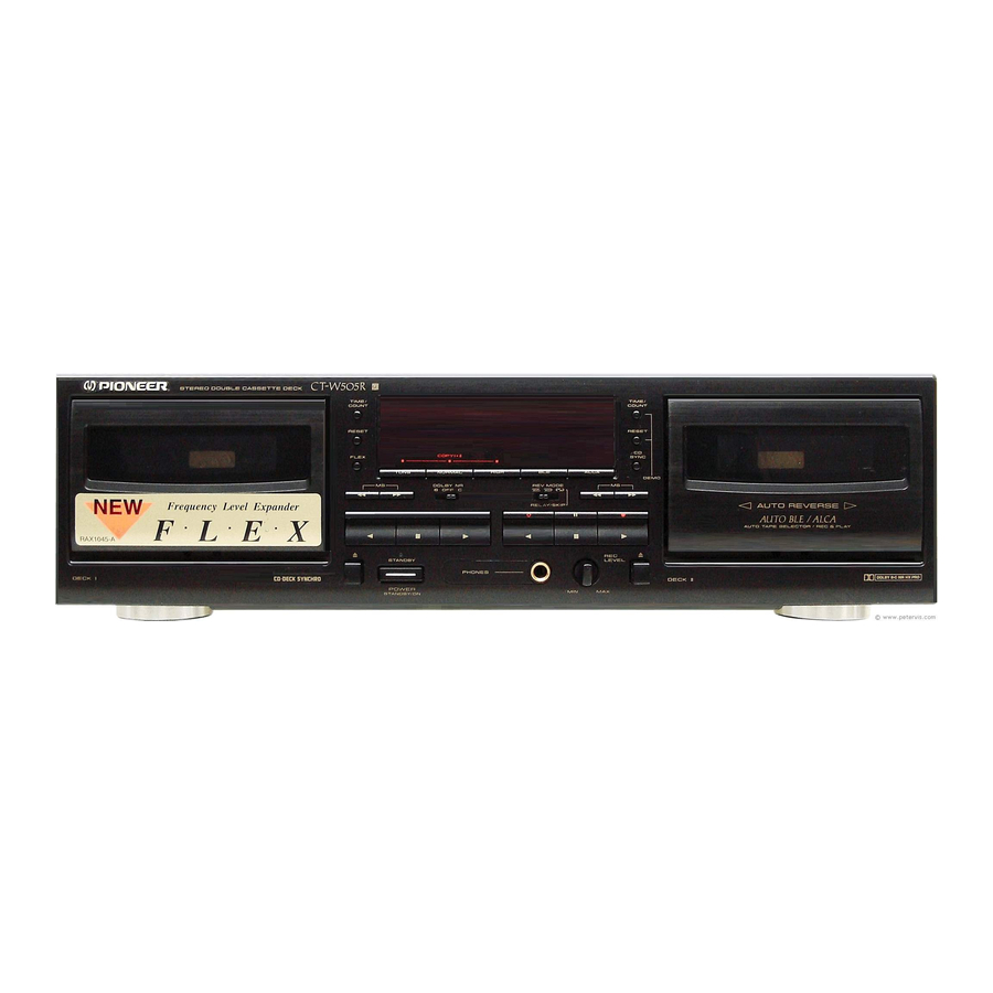
Pioneer CT-W505R Service Manual
Stereo double cassette deck
Hide thumbs
Also See for CT-W505R:
- Operating instructions manual (37 pages) ,
- Operating instructions manual (20 pages)
Advertisement
Quick Links
STEREO DOUBLE CASSETTE DECK
CT-W505R
Refer to the service manual RRV1475 for CT-W505R/KUXJ.
THIS MANUAL IS APPLICABLE TO THE FOLLOWING MODEL(S) AND TYPE(S).
Model
Type
CT-W505R
HYXJ7
HVXJ7
PIONEER ELECTRONIC CORPORATION
PIONEER ELECTRONICS SERVICE, INC. P.O. Box 1760, Long Beach, CA 90801-1760, U.S.A.
PIONEER ELECTRONIC (EUROPE) N.V. Haven 1087, Keetberglaan 1, 9120 Melsele, Belgium
PIONEER ELECTRONICS ASIACENTRE PTE. LTD. 501 Orchard Road, #10-00 Wheelock Place, Singapore 238880
PIONEER ELECTRONIC CORPORATION 1998
Power Requirement
AC220–230V
AC230–240V
∗
: Alter the wiring of the power-supply block at the primary winding of Power transformer referring to
the Line Voltage Selection described in Service Manual.
CONTENTS
1. CONTRAST OF MISCELLANEOUS PARTS ..... 2
2. SCHEMATIC DIAGRAM ..................................... 5
3. PCB CONNECTION DIAGRAM ......................... 7
4-1, Meguro 1-Chome, Meguro-ku, Tokyo 153-8654, Japan
The voltage can be converted by the following method.
∗
AC230–240V,
∗
AC220–230V,
T–DZE OCT. 1998 Printed in Japan
ORDER NO.
RRV2038
Advertisement

Summary of Contents for Pioneer CT-W505R
- Page 1 PIONEER ELECTRONICS SERVICE, INC. P.O. Box 1760, Long Beach, CA 90801-1760, U.S.A. PIONEER ELECTRONIC (EUROPE) N.V. Haven 1087, Keetberglaan 1, 9120 Melsele, Belgium PIONEER ELECTRONICS ASIACENTRE PTE. LTD. 501 Orchard Road, #10-00 Wheelock Place, Singapore 238880 PIONEER ELECTRONIC CORPORATION 1998...
- Page 2 = 5621 ........... RN1/4PC 5 6 2 1 F ÷ Reference Nos. indicate the pages and Nos. in the service manual for the base model. CONTRAST TABLE CT-W505R/HYXJ7, HVXJ7 and CT-W505R/KUXJ are constructed the same except for the following: Part No. Ref.
-
Page 3: Exploded Views
CT-W505R Part No. Ref. Mark Remarks Symbol and Description CT-W505R CT-W505R CT-W505R KUXJ HYXJ7 HVXJ7 ∗2 Fuse (5A) (for AC power cord) Not used Not used PEK1003 No. 3 ∗2 LED Lens Cover Not used RNK2206 RNK2206 No. 4 ∗2... - Page 4 CT-W505R CONTRAST OF PCB ASSEMBLIES MAIN UNIT RWZ4323 and RWZ3721 are constructed the same except for the following: Part No. Mark Symbol and Description Remarks RWZ3721 RWZ4323 IC501 PD5350A PD5505A D503 1SS254 Not used ∗ S1000 Not used RSA1002 ∗...
- Page 5 CT-W505R 2. SCHEMATIC DIAGRAM Note: When ordering service parts, be sure to refer to "EXPLODED VIEWS AND PARTS LIST" or "PCB PARTS LIST". SCHEMATIC DIAGRAM (1/2) MAIN UNIT (RWZ4323) MAIN UNIT (RWZ4323) TRANSFORMER Cover PCB (RNZ3323) AC POWER CORD PDG1058 (HYXJ7 type)
- Page 6 CT-W505R SCHEMATIC DIAGRAM (2/2) MAIN UNIT (RWZ4323)
- Page 7 CT-W505R 3. PCB CONNECTION DIAGRAM NOTE FOR PCB DIAGRAMS: Symbol in PCB Symbol in Schematic Symbol in PCB Symbol in Schematic 1. Part numbers in PCB diagrams match those in the schematic Part Name Part Name Diagrams Diagrams Diagrams Diagrams diagrams.
- Page 8 CT-W505R SIDE A 3.2 MAIN UNIT MAIN UNIT Q1001 Q1004 IC1011 IC1004 Q901 IC1003 Q771 Q772 IC502 Q851 VR851 Q852 Q853 Q854 Q855 Q857 IC1001 Q856 IC1002 VR451 VR452 Q405 Q414 Q401 To TRANSFORMER 2 UNIT Q402 J1001 Q451 Q452...
- Page 9 CT-W505R SIDE A Q171 Q174 Q651 Q652 IC601 Q751 Q752 VR101 VR104 Q101 Q102 VR301 IC101 Q105 Q106 Q143 Q146 VR302 VR305 VR552 Q331 Q332 IC552 Q554 Q801 Q807 VR551 IC551 VR801 VR802 VR553 (RNP1728–A) To 2 Mechanism Unit (3/3)
- Page 10 CT-W505R SIDE B MAIN UNIT IC171 IC301 IC302...
- Page 11 CT-W505R SIDE B (RNP1728–A)


