
Related Manuals for Sony CCU-790


Summary of Contents for Sony CCU-790
- Page 1 CAMERA CONTROL UNIT CCU-790/790P OPERATION MANUAL [English] 1st Edition (Revised 1)
- Page 2 For the customers in Europe (for CCU-790P) WARNING The manufacturer of this product is Sony Corporation, 1-7-1 Konan, Minato-ku, Tokyo, Japan. To reduce the risk of fire or electric shock, The Authorized Representative for EMC and product safety is do not expose this apparatus to rain or Sony Deutschland GmbH, Hedelfinger Strasse 61, 70327 moisture.
-
Page 3: Table Of Contents
Rear panel ................. 6 Internal Parts and Internal Boards........9 Internal parts ................9 Internal boards ................9 Connecting the CCU-790/790P to the Video Camera ..10 Notes on connections .............. 10 Self-Diagnostics ..............11 Settings of the camera..............11 Status display of the camera system ........11 Self-diagnostics of the camera system........ -
Page 4: Overview
SDI signal output is selected for the VBS/SDI-1 connector). • The CCU-790/790P supports communications between the video camera and the CCU-790/790P over either a triax cable or coaxial cable. (Power, however, is not supplied to the video camera in the case of coaxial cable.) -
Page 5: Function And Location Of Parts And Controls
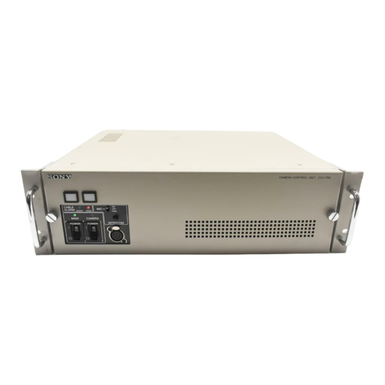
Function and Location of Parts and Controls Front panel a Red tally lamp b Green tally lamp c MIC/PGM switch d INTERCOM level control CAMERA CONTROL UNIT CCU-790 CABLE ALARM SHORT OPEN MAIN CAMERA INTERCOM POWER POWER e INTERCOM connector... -
Page 6: Rear Panel
Rear panel a CAMERA connector b AUDIO OUTPUT connectors c INPUT connectors d OUTPUT connectors e REMOTE connector f ETHERNET connector k SDI OUTPUT connectors j AC IN connector i WF MODE connector h MIC REMOTE connector g INTERCOM/TALLY/PGM connector a CAMERA connector (triax connector) Connects to the CA-570/570P/590/590P/905K/F/T A REFERENCE INPUT connectors... - Page 7 A VBS (composite video signal)/SDI (serial digital signal. interface)-1, VBS/SDI-2, VBS/SDI-3 connectors (BNC type) For details on the internal boards, consult your Sony Supply the signal from the video camera in composite or service personnel. SDI format. Use the switch on the internal board to select the composite D SDI (serial digital interface) RET-3/4 (return video video signal or SDI signal.
- Page 8 AC IN (AC power input) connector Connects to an AC power source using the supplied AC power cord. Secure the power cord to the CCU-790/790P using the supplied plug holder. Function and Location of Parts and Controls...
-
Page 9: Internal Parts And Internal Boards
Fuses CARBON: Carbon microphone (power supply, 20 dB gain) When the fuses need to be replaced, consult your Sony ECM: Electret condenser microphone (power supply, 40 service personnel. dB gain) DYNAMIC: Dynamic microphone (no power supply, 60... -
Page 10: Connecting The Ccu-790/790P To The Video Camera
CCU-790/790P CA-905K/F/T Note The maximum power output from the CAMERA connector of the CCU-790/790P is 360 VA (including a cable loss). Do not To an AC power source connect any equipment which consumes more than 360 VA of power. Notes on connections... -
Page 11: Self-Diagnostics
Self-Diagnostics The CCU-790/790P is equipped with the self-diagnostic function and you can display the self-diagnostics results of the system and the internal boards of the CCU-790/790P on the following monitors. • A picture monitor connected to the PIX connector • An SDI monitor connected to the VBS/SDI-3 connector •... -
Page 12: Settings Of The Network
The following pages appear only when the CCU-790/790P Page 2 is set so that it connects to the system through the Ethernet. In order for the CCU-790/790P to establish connection via Ethernet, internal settings must be made. For details on the internal settings, consult your Sony service personnel. -
Page 13: Self-Diagnostics Results Of The Ccu-790/790P Internal Boards
Page 2 DM board CAM Video: Status of the Y, R-Y, and B-Y signals of the NS Mode: Setting for the ETHERNET connection mode triax signal LEGACY: Connection mode for the REMOTE Skin Gate: Reception status of the Skin gate signal from connector (factory-setting) the camera BRIDGE: ETHERNET connection mode... -
Page 14: Self-Diagnostics Results Of The Camera Internal Boards
Gen Lock: Locking status BoardID: ID number of the IV board CCU Power: CCU power supply type (AC/DC) and power EN board supply status BATT Volt: Voltage of the coin battery supplied with the AT board PLL Volt: Status of the PLL circuit of the AT board CCU Mode: Operation mode of the CCU PLD: Status of the PLD mounted on the AT board and program version of the PLD... -
Page 15: Rom Version Indication
CCU-790P: 100 V/120 V/220 to 240 V AC selectable, 50/60 Hz (factory setting: 220 V to 240 V AC) Power consumption CCU-790: 3.5 A max. for entire system CCU-790P: 4.2 A max. for entire system Exiting the Self-diagnostic mode Peak inrush current... -
Page 16: Output Signals
Note 700 mVp-p, 75 ohms BNC type (1) Always verify that the unit is operating properly before use. SONY WILL NOT BE LIABLE FOR DAMAGES 1.0 Vp-p, 75 ohms OF ANY KIND INCLUDING, BUT NOT LIMITED BNC type (1) NTSC: 714 mVp-p, 75 ohms... - Page 17 The material contained in this manual consists of information Trademark that is the property of Sony Corporation and is intended solely Ethernet is a registered trademark of Xerox Corporation. for use by the purchasers of the equipment described in this manual.
- Page 18 CCU-790/790P Sony Corporation (UC/CE) 3-210-787-02 (1) © 2007...