
Related Manuals for Philips MultiOne


Summary of Contents for Philips MultiOne
-
Page 1: User Manual
MultiOne User manual This manual has been updated for MultiOne version 2.6.5 © Philips Lighting B.V. 2014... -
Page 2: Introduction
FLUO), but this does not mean that every device from a product group does support all features. Philips MultiOne is supported by Windows XP + SP3, Windows 7, Windows 8 and 8.1 operating systems. It works only in combination with the Philips LCN8600 MultiOne interface USB2DALI, with Philips LCN8650 MultiOne interface USB2ZigBee or with Philips LCN9600 MultiOne interface SimpleSet. -
Page 3: Table Of Contents
Selecting devices for communication ..............16 9.2.3 Managing user-defined groups ................17 9.2.4 Managing groups ......................18 10 Working with the Philips LCN8650 MultiOne interface USB2ZigBee ......20 10.1 The main application window ..................20 10.2 Connecting to a ZigBee network ................20 10.2.1... - Page 4 User Manual Philips MultiOne 10.3.3 Managing zones ....................... 22 11 Working with the Philips LCN9600 MultiOne interface SimpleSet ......25 11.1 The main application window ..................25 11.2 Scanning a SimpleSet device ..................25 11.2.1 Identifying devices ....................25 11.2.2 Auto read ........................
- Page 5 Configuring multiple DALI devices (simultaneously) ........... 55 12.8 Configuring multiple DALI devices (consecutively) ..........56 12.8.1 MultiOne Basic ......................56 12.8.2 MultiOne (full version) .................... 56 12.9 Offline feature configuration preparation ............... 57 12.10 Accessing diagnostics ..................... 57 12.11 Sending DALI commands ....................61 12.12...
- Page 6 13 Keyboard shortcuts ........................74 14 Software Update ..........................75 15 Copyright ............................77 16 Disclaimer ............................78 17 Limitations of damages ....................... 79 18 List of tables ............................ 80 19 Index ..............................81 © Philips Lighting B.V. 2014 Page 6 / 81...
-
Page 7: System Requirements
User Manual Philips MultiOne System requirements The minimum system requirements for using MultiOne are: PC or laptop with Microsoft Windows XP SP3, Windows 7, Windows 8 or 8.1 USB 2.0 ports: o Two free USB 2.0 ports for use with USB2DALI interface o One free USB 2.0 port for use with USB2ZigBee interface... -
Page 8: Downloading And Installing Multione And The Documentation Package
UserManual.pdf (document) RELEASE_NOTES.txt (document) The MultiOne installation file is the installer for the full version of MultiOne. This document applies to this version of the software. The MultiOne Workflow installation file is the version of MultiOne which is meant to be used in a production environment. -
Page 9: Attention Points
Philips MultiOne 5 Attention points 5.1 General Before starting MultiOne, make sure that the correct interface (USB2DALI, USB2ZigBee or SimpleSet) has been connected to your computer. When upgrading the Windows Operating System, make sure the connection settings are correct when using MultiOne again. -
Page 10: The Multione Interfaces
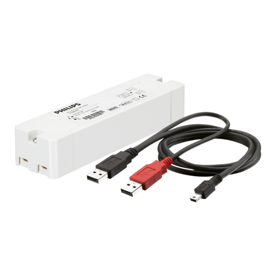
The MultiOne interfaces 6.1 DALI The Philips LCN8600 MultiOne interface USB2DALI (USB2DALI interface) is the interface between the PC and the DALI devices. It has a mini- USB input connector and two parallel DALI output connectors. The USB2DALI interface status is indicated by three LED’s located near the mini-USB connector. -
Page 11: Zigbee
User Manual Philips MultiOne 6.2 ZigBee The Philips LCN8650 MultiOne interface USB2ZigBee (USB2ZigBee interface) is an USB dongle which interfaces between the PC and the ZigBee devices. 6.3 SimpleSet The Philips LCN9600 MultiOne interface SimpleSet (SimpleSet interface) is an USB device which interfaces between the PC and the SimpleSet devices. -
Page 12: Starting Multione
USB2ZigBee or SimpleSet) has been connected to your computer. 7.1 Application mode selector When starting MultiOne, the first window that appears is the Application Mode Selector. Here, you can choose an application mode, based on the tasks you would like to perform. The application window also has links to the documentation. - Page 13 User Manual Philips MultiOne You can always go back to the Application Mode Selector by selecting View Application Mode Selector from the main application window. © Philips Lighting B.V. 2014 Page 13 / 81...
-
Page 14: Selecting The Interface
USB2ZigBee or SimpleSet) to work with. First select the protocol: DALI, ZigBee or SimpleSet, when needed also indicate the selected interface and port. This protocol can always be changed later, by going to the Tools Connection settings. © Philips Lighting B.V. 2014 Page 14 / 81... -
Page 15: Working With The Philips Lcn8600 Multione Interface Usb2Dali
Working with the Philips LCN8600 MultiOne interface USB2DALI Before using MultiOne with the USB2DALI interface make sure that all devices that need to be commissioned are connected to the mains and the DALI network. Finally the DALI network must be connected to one of the DALI connectors of the USB2DALI interface. -
Page 16: Selecting Devices For Communication
User Manual Philips MultiOne When starting MultiOne, the DALI devices connected to the USB2DALI interface are not automatically identified. There are two methods for identifying the devices with corresponding buttons in the Network on the left-hand side of the application window: Scan network and Commission. -
Page 17: Managing User-Defined Groups
The purpose of user-defined groups is that they facilitate easy clustering so that a number of devices can be addressed simultaneously. The user-defined groups are lost when MultiOne is closed. A new user-defined group can be created by right-clicking User-defined groups and selecting Add new group. -
Page 18: Managing Groups
Identify the device o Add to, add the device to one group o Configure…, add device to multiple groups With a right-click on a device in a group you can: © Philips Lighting B.V. 2014 Page 18 / 81... - Page 19 Identify the devices in the group o Configure…, add/remove multiple devices to/from the group o Clear group, remove the devices from the group The number of devices in a DALI group is limited to 64. © Philips Lighting B.V. 2014 Page 19 / 81...
-
Page 20: Working With The Philips Lcn8650 Multione Interface Usb2Zigbee
The ZigBee devices and networks in the area of the USB2ZigBee interface are not automatically known. To find devices and networks in the area press Connect to network: MultiOne scans for an open network in the area and connects to the network. After connecting has finished, the network and the found devices are shown in the Network panel. -
Page 21: Selecting Devices For Communication
After having connected to the network, the Network panel shows all devices and the network to which MultiOne is connected. By clicking on a device or network you will make that particular device or network the active one, meaning that all actions will be performed on this device or network only, and will be ignored by all other devices or networks. -
Page 22: Managing Networks
With a right-click on a device in a zone you can: o Identify the device o Add to, move the device to an another or new zone o Configure…, move the device to another zone © Philips Lighting B.V. 2014 Page 22 / 81... - Page 23 With a right-click on a zone you can: o Identify the zone o Configure…, add/remove multiple devices to/from the zone. If other zones become empty, they will be removed © Philips Lighting B.V. 2014 Page 23 / 81...
- Page 24 User Manual Philips MultiOne o Remove zone, the zone will be removed and the devices will become unassigned © Philips Lighting B.V. 2014 Page 24 / 81...
-
Page 25: Working With The Philips Lcn9600 Multione Interface Simpleset
11.2.1 Identifying devices The SimpleSet device near the SimpleSet interface is not automatically known by MultiOne. To get the device press Scan for device: a pop-up will appear indicating the device must touch the interface. Touch and hold the device close to the SimpleSet interface ©... - Page 26 User Manual Philips MultiOne until the scan has completed. The scanned device will be shown in the Network panel. © Philips Lighting B.V. 2014 Page 26 / 81...
-
Page 27: Auto Read
11.4 Starting communication In order to communicate with a SimpleSet device, the device has to touch the SimpleSet interface. Before starting the communication MultiOne will show a pop-up when the device is not near the SimpleSet interface. This pop-up waits until the device and the SimpleSet interface touch, or disappears after 20 seconds. -
Page 28: Working With Multione
Apart from using Read and Write on the toolbar, you can directly send DALI commands. This can be done on the Commands tab and the Scheduler tab. In the Preferences window it is possible to enable extra verification when writing (see chapter 12.15). © Philips Lighting B.V. 2014 Page 28 / 81... -
Page 29: Configuring Device Features
Philips MultiOne 12.3 Configuring device features You can configure all features that are supported by a specific Philips device. For any device selected in the Network, the Device features tab displays the set of device features that corresponds to this device. Upon selecting another device, the Device features tab will be updated as well. - Page 30 FLUO), but this does not mean that every device belonging to a certain product group will automatically support all of its features listed here. For an overview of supported device features see Supported features. © Philips Lighting B.V. 2014 Page 30 / 81...
-
Page 31: 1-10V Min Dim Level
Use the slider or the text field to select a value. The value represents the light level. 12.3.2 ActiLume General Product group CONTROL Description Use this feature to configure general ActiLume settings. © Philips Lighting B.V. 2014 Page 31 / 81... -
Page 32: Actilume Mode
Click the Reset to factory defaults button to reset the current mode to the factory defaults. Please refer to the ActiLume DALI gen2 Application Guide for further details. 12.3.4 ActiLume Scene Product group CONTROL © Philips Lighting B.V. 2014 Page 32 / 81... -
Page 33: Actilume Wireless General
Please refer to the ActiLume DALI gen2 Application Guide for further details. 12.3.5 ActiLume Wireless General Product group CONTROL Description Use this feature to configure general ActiLume Wireless settings. Usage © Philips Lighting B.V. 2014 Page 33 / 81... -
Page 34: Actilume Wireless Mode
Use the various drop down boxes, check boxes and text fields to make a configuration. Please refer to the ActiLume Wireless Application Guide for further details. 12.3.7 Active Cooling Product group © Philips Lighting B.V. 2014 Page 34 / 81... -
Page 35: Adjustable Light Output
Alternatively, use the table to enter values directly. NOTE: For a detailed technical description of the characteristics of the device model, like constraints and limitations, please refer to Device-specific technical description. 12.3.8 Adjustable Light Output Product group © Philips Lighting B.V. 2014 Page 35 / 81... -
Page 36: Adjustable Output Current
The current can be set in two ways: Select the External Rset check box: Adjustment of the output current is not configured using MultiOne, but the value of an external resistor adjusts the output current Use the slider or the text field to select a value. The value represents the nominal output current 12.3.10... -
Page 37: Ampdim
Alternatively, use the table to directly enter values. NOTE: For a detailed technical description of the characteristics of the device model, like constraints and limitations, please refer to Device-specific technical description. © Philips Lighting B.V. 2014 Page 37 / 81... -
Page 38: Constant Light Output
Plus button to individually add scenes. When creating a new schedule, in the dialog window that pops up you can either select an empty schedule, a default schedule or a custom schedule. © Philips Lighting B.V. 2014 Page 38 / 81... - Page 39 Alternatively, use the table to enter values directly. Single or multiple table rows can be removed by clicking the Minus button. NOTE: The reliable use of Constant Light Output requires extensive LED specification assessment of life time behavior of LEDs. © Philips Lighting B.V. 2014 Page 39 / 81...
-
Page 40: Corridor Mode
Prolong time: When reaching background level, the time after which the device will be switched off Activation time: The time during which a mains signal must be detected, before the device will switch to Corridor Mode © Philips Lighting B.V. 2014 Page 40 / 81... -
Page 41: Dimming Interface
The available dimming interfaces are stored in the device and therefore need to be read out. When the interfaces are found it will be possible to select Automatic selection (enable all interfaces), No dimming (disable all interfaces) or a single interface. © Philips Lighting B.V. 2014 Page 41 / 81... -
Page 42: Dynadimmer
The midnight shift option is unavailable when the Time based check box has been selected. © Philips Lighting B.V. 2014 Page 42 / 81... - Page 43 Click the New button to create a default schedule or click the Plus button to add scenes individually. Drag the points or the lines in the graph to create the desired © Philips Lighting B.V. 2014 Page 43 / 81...
-
Page 44: Dc Emergency
After reading out the device, MultiOne tries to match the midnight point offset with a location. In case the midnight point offset does not match to a location or the midnight point offset matches multiple locations, MultiOne will show “No location”. - Page 45 The value represents the arc power level when in DC Emergency mode (the label on the right gives the approximate light level percentage). Select the Allow dimming check box to allow dimming when in DC Emergency mode. © Philips Lighting B.V. 2014 Page 45 / 81...
-
Page 46: End Of Life Indication
The value for Energy consumed can be reset by selecting the Reset meter check box followed by clicking Write on the toolbar. The value for Total energy consumed cannot be reset. © Philips Lighting B.V. 2014 Page 46 / 81... -
Page 47: Lamp Burn-In
12.3.20 Lamp Selection Product group HID, FLUO Description Use the Lamp Selection feature to select the lamp type that is connected to the device. Options depend on the device model. Usage © Philips Lighting B.V. 2014 Page 47 / 81... -
Page 48: Light Source Operating Hours
Constant Light Output and End Of Life indication. Usage Use the slider or the text field to select a value. The value represents the number of operating hours. 12.3.22 LineSwitch Product group HID, LED © Philips Lighting B.V. 2014 Page 48 / 81... -
Page 49: Lumistep
Select the Enable check box to use this feature. This feature has the following parameters: Dim period: Use the drop down box to select the wanted dim period. This is the time period the dim level will be used. © Philips Lighting B.V. 2014 Page 49 / 81... -
Page 50: Min Dim Level
This feature provides an interface for setting the min dim level of a device. Usage Select the Enable check box to use this feature. Use the slider or the text field to select a value. The value represents the min dim level in percentage. © Philips Lighting B.V. 2014 Page 50 / 81... -
Page 51: Module Temperature Protection
Based on the device model, the feature is shown in either temperature (degrees Celsius) or resistance values (in Ohm). NOTE: For a detailed technical description of the characteristics of the device model, like constraints and limitations, please refer to Device-specific technical description. © Philips Lighting B.V. 2014 Page 51 / 81... -
Page 52: Quick Lamp Start
When the Ignore toggle limits check box is selected, the normal toggle limits are ignored and dimming starts directly. If this is not checked the normal toggle limits are used. © Philips Lighting B.V. 2014 Page 52 / 81... -
Page 53: Using The Features Summary
To save and open a feature configuration file, the Device features tab must be active. Feature configurations can be saved to a file for later use. To do so, first select the Device features tab to make feature configurations © Philips Lighting B.V. 2014 Page 53 / 81... - Page 54 Feature configuration files can be distributed to other users of MultiOne. A typical example is that one user prepares a feature configuration file, and then sends it to another user who uses MultiOne Basic. This user then opens the file and configures the connected device.
-
Page 55: Configuring A Single Device
The procedure to simultaneously configure multiple devices of the SAME TYPE AND VERSION is as follows (Note: this method will not work with MultiOne Basic): 1. Connect maximum 64 devices of the SAME TYPE AND VERSION, in parallel to the DALI connectors of the USB2DALI interface 2. -
Page 56: Configuring Multiple Dali Devices (Consecutively)
There are situations in which multiple devices need to be configured one after another. The procedure to consecutively configure multiple devices of the SAME TYPE AND VERSION differs slightly between MultiOne Basic and MultiOne (full version). 12.8.1 MultiOne Basic 1. Connect one device 2. -
Page 57: Offline Feature Configuration Preparation
Network. Expand it by clicking the + sign to see the list of virtual devices. Note that virtual devices do not have a short address and MultiOne will show Broadcast on the location of the short address. Virtual devices can only be addressed using broadcast commands. - Page 58 Thermal Guard activated as a consequence of high temperature level. EOL driver incandescence End-Of-Life situation showing incandescent mode of failures operation of the lamp. EOL lamp incandescence End-Of-Life situation showing incandescent mode of © Philips Lighting B.V. 2014 Page 58 / 81...
- Page 59 HID driver switched-on with a non-supported or corrupt lamp table selected. a) lamp replacement triggers an erase of predefined lamp-specific items such as ignition attempts, lamp errors. Diagnostics for a LED device might look as follows: © Philips Lighting B.V. 2014 Page 59 / 81...
- Page 60 Though there is a case correlation between T and internal driver case temperature, the difference can vary depending on current setting of driver. System starts Represents the number of times the LED driver is © Philips Lighting B.V. 2014 Page 60 / 81...
-
Page 61: Sending Dali Commands
20000 ms, and the diagnostic information is read at startup within 20 s, this check box will be selected indicating startup condition. 12.11 Sending DALI commands To manually send DALI commands select the Commands tab. © Philips Lighting B.V. 2014 Page 61 / 81... -
Page 62: Querying Devices
Besides a number of DALI commands using the DTR value, also Reset, Step Up and Step Down are direct available. 12.12 Querying devices To automatically execute a number of standard DALI query commands select the Query tab. © Philips Lighting B.V. 2014 Page 62 / 81... -
Page 63: Working With Dali Command Scripts
To run a series of DALI commands, a script can be created in the Scheduler tab. This script can be executed any number of times. Furthermore it is possible to save the script to a file for easy reuse. © Philips Lighting B.V. 2014 Page 63 / 81... - Page 64 If a command parameter is required, enter it into the Data field. © Philips Lighting B.V. 2014 Page 64 / 81...
-
Page 65: The Logging Window
The time the feature was read or written or the time the command was sent. The format of the timestamp is: <date> <time>. Address The short address to which the feature or command was sent. In case Broadcast is mentioned, all devices are addressed. Description © Philips Lighting B.V. 2014 Page 65 / 81... - Page 66 User Manual Philips MultiOne The name of the feature or the actual DALI command. Result Result of the communication. © Philips Lighting B.V. 2014 Page 66 / 81...
-
Page 67: Setting Preferences
Philips MultiOne 12.15 Setting preferences MultiOne has a preferences window that allows you to customize the way MultiOne works. To access the preferences window select Tools Preferences. The Preferences window that pops up allows you to set MultiOne preferences. -
Page 68: Manually Selecting The Usb2Dali Interface
MultiOne update itself. Automatic - Check only: MultiOne will automatically check for updates and notify the user if a new version is available. The user can then allow MultiOne to download and install the update. Manual: MultiOne will do nothing and the user has to force MultiOne to check, download and install any update. - Page 69 User Manual Philips MultiOne In the pop-up window it is then possible to select the desired port. © Philips Lighting B.V. 2014 Page 69 / 81...
-
Page 70: Enabling/Disabling The Power Supply Of The Usb2Dali Interface
USB2DALI interface to switch on or off its internal power supply, you can do so using the option Tools Power supply. 12.18 Supported features The table below gives an overview of all features that are supported by MultiOne and to which product groups they apply. Table 3 Supported features... -
Page 71: Device-Specific Technical Descriptions
12.20.2 Reporting of errors when reading from a device When after reading from a device a mismatch is signaled between the parameters of the device and MultiOne, MultiOne will not correct the parameters, but will show a red border. 12.20.3 Reporting of errors when entering incorrect values in a feature Entering an incorrect value for a parameter will be indicated by a red border. -
Page 72: Troubleshooting
Write on the toolbar. Problem: I would like to know more technical details of a device. Solution: Please refer to the Philips website for more detailed information For LED driver, both indoor and outdoor, visit: www.philips.com/Xitanium... - Page 73 User Manual Philips MultiOne For FLUO drivers visit: www.philips.com/HFR-Intelligent For controls visit: www.philips.com/Actilume © Philips Lighting B.V. 2014 Page 73 / 81...
-
Page 74: Keyboard Shortcuts
User Manual Philips MultiOne Keyboard shortcuts Keyboard shortcuts can make it easier to work with MultiOne without using the mouse. USB2DALI interface USB2ZigBee interface The File menu Working with feature configuration files Ctrl+O Open a feature configuration Not supported file... -
Page 75: Software Update
Setting Preferences for more info. If the preference is set to Manual then the user can check for an update on MultiOne by selecting Help Check for updates option. - Page 76 After downloading the update status will inform the user to restart to continue. Restarting MultiOne will install the update. A successful update of MultiOne will be shown in the update status. © Philips Lighting B.V. 2014 Page 76 / 81...
-
Page 77: Copyright
Philips. Brands and product names are trademarks or registered trademarks of their respective companies. -
Page 78: Disclaimer
User Manual Philips MultiOne Disclaimer Philips makes no warranty of any kind with regard to this material, including, but not limited to, the implied warranties of merchantability and fitness for a particular purpose. Philips assumes no responsibility for any error that may appear in this document. -
Page 79: Limitations Of Damages
© Philips Lighting B.V. 2014 Page 79 / 81... -
Page 80: List Of Tables
Philips MultiOne List of tables Table 1 HID diagnostics ........................58 Table 2 LED diagnostics ........................60 Table 3 Supported features ....................... 70 Table 4 Product-specific Philips web sites ..................71 © Philips Lighting B.V. 2014 Page 80 / 81... -
Page 81: Index
Network ..........16, 17, 21, 22, 23, 26, 27, 28, 52, 53, 54, 55, 59, 68, 69 Quick Lamp Start ..........................50, 67 Summary ............................. 29, 51, 67 Touch and Dim ........................39, 50, 52, 67 user-defined group ......................... 17, 18, 19 © Philips Lighting B.V. 2014 Page 81 / 81...