Table of Contents
Advertisement
Quick Links
Advertisement
Table of Contents

Related Manuals for Acer AcerNote 970


Summary of Contents for Acer AcerNote 970
- Page 1 AcerNote 970 Service Guide...
- Page 2 About this Manual Purpose This service guide contains reference information for the 370 notebook computer. It gives the system and peripheral specifications, shows how to identify and solve system problems and explains the procedure for removing and replacing system components. It also gives information for ordering spare parts.
- Page 3 Forms This appendix contains standard forms that can help improve customer service. Related product information AcerNote 970 User's Manual contains system description and general operating instructions. Vesuvius-LS Chipset Data Sheets contain information on the system core chips (V1-LS, V2-LS, V3-LS).
- Page 4 Conventions The following are the conventions used in this manual: Represents text input by the user. Text entered by user Denotes actual messages that appear onscreen. Screen messages a , e , s , etc. Represent the actual keys that you have to press on the keyboard.
-
Page 5: Table Of Contents
Table of Contents Chapter 1 System Introduction Overview ......................1-1 1.1.1 Features....................1-1 1.1.2 FlashStart - Turning the Notebook Computer On and Off .......1-2 1.1.3 Ports ......................1-3 1.1.4 Automatic Tilt-up Keyboard..............1-4 1.1.5 Indicator Light ..................1-5 1.1.6 Keyboard Hotkey List ................1-6 System Specification Overview ................1-9 Board Layout ......................1-11 1.3.1 System Board (Top Side) ..............1-12... - Page 6 1.5.16 PCMCIA....................1-39 1.5.17 Parallel Port ..................1-40 1.5.18 Serial Port....................1-40 1.5.19 Touchpad.....................1-40 1.5.20 SIR ......................1-41 1.5.21 LCD .....................1-41 1.5.22 CD-ROM ....................1-42 1.5.23 Diskette Drive ..................1-42 1.5.24 Hard Disk Drive..................1-43 1.5.25 Keyboard .....................1-43 1.5.26 Battery ....................1-44 1.5.27 DC-DC Converter.................1-44 1.5.28 DC-AC Inverter ..................1-44 1.5.29 AC Adapter ..................1-45 System Block Diagrams..................1-46...
- Page 7 ESS1688W Sound Controller................2-56 2.5.1 Block Diagram ..................2-56 2.5.2 Pin Diagram..................2-57 2.5.3 Pin Descriptions ...................2-58 Philips 87C552 System Management Controller ..........2-63 2.6.1 Features....................2-63 2.6.2 Block Diagram ..................2-64 2.6.3 Pin Diagram..................2-65 2.6.4 Pin Descriptions ...................2-66 NS87336VLJ Super I/O Controller ..............2-68 2.7.1 Features....................2-68 2.7.2 Block Diagram ..................2-70 2.7.3...
- Page 8 3.4.1 Date and Time ..................3-5 3.4.2 Diskette Drives..................3-5 3.4.3 Hard Disks .................... 3-6 3.4.4 Num Lock After Boot................3-6 3.4.5 LCD Expansion Mode ................3-6 3.4.6 Internal Cache..................3-8 3.4.7 External Cache ..................3-8 3.4.8 Enhanced IDE Features ................ 3-8 3.4.9 Onboard Communication Ports .............
- Page 9 Removing the Keyboard ..................4-7 Removing or Replacing the CPU ................4-9 Removing the Display..................4-10 Disassembling the Housing.................4-11 4.5.1 Detaching the Lower Housing from the Inside Assembly ......4-11 4.5.2 Replacing the Hard Disk Drive .............4-12 4.5.3 Replacing Memory ................4-12 4.5.4 Detaching the Upper Housing from the Inside Assembly ......4-14 4.5.5 Removing the Touchpad ..............4-15 4.5.6...
- Page 10 List of Figures 1- 1 FlashStart Automatic Power-on Switch (Lid Switch) ..........1-2 1- 2 Ports ........................1-3 1- 3 Indicator Lights ....................1-5 1- 4 System Board (Top Side)..................1-12 1- 5 System Board (Bottom Side)................1-13 1- 6 Media Board (Top Side) ..................1-14 1- 7 Media Board (Bottom Side).................1-15 1- 8...
- Page 11 2-20 T62.036.C Pin Diagram ..................2-97 2-21 T62.039.C/T62.055.C Pin Diagram ..............2-99 Removing the Battery Pack ..................4-2 Using Plastic Stick on Connector With Lock............4-3 Disassembly Flow ....................4-5 Removing the Module...................4-6 Removing the Display Hinge Covers..............4-7 Removing the Center Hinge Cover ...............4-7 Lifting Out the Keyboard ..................4-8 Unplugging the Keyboard Connectors and Removing the Keyboard......4-8 Removing the CPU Module Lock ................4-9 4-10...
- Page 12 List of Tables Port Descriptions....................1-4 Indicator Status Descriptions................1-5 Hotkey List Descriptions..................1-6 Eject Menu Descriptions ..................1-8 System Specifications..................1-9 Mainboard Jumpers Pads Settings (Bottom Side) ..........1-18 Memory Address Map ..................1-21 Interrupt Channel Map ..................1-21 I/O Address Map ....................1-22 1-10 DMA Channel Map....................1-23 1-11...
- Page 13 1-35 Battery Specifications ..................1-44 1-36 DC-DC Converter Specifications.................1-44 1-37 DC-AC Inverter Specifications ................1-45 1-38 AC Adapter Specifications ..................1-45 1-39 Environmental Requirements................1-48 1-40 Mechanical Specifications...................1-49 Major Chips List ....................2-1 V1-LS Pin Descriptions ..................2-10 V2-LS Pin Descriptions ..................2-20 V3-LS Pin Descriptions ..................2-24 NMG2090 Pin Description Conventions ..............2-32 NMG2090 Pin Descriptions .................2-32 RCV288Aci/SVD Signal Type Annotation............2-44...
-
Page 14: Overview
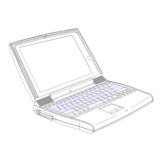
C h a p t e r C h a p t e r Introduction This chapter introduces the notebook computer, and describes its features and specifications. 1.1. Overview This Pentium-based notebook computer combines high-performance, versatility, multimedia capabilities and a truly advanced power management system. 1.1.1 Features PERFORMANCE •... -
Page 15: Flashstart - Turning The Notebook Computer On And Off
• Sleek, smooth and stylish design • Automatic tilt-up, full-sized, full-function keyboard • Wide and comfortable palm rest • Ergonomically-centered touchpad pointing device EXPANSION • PC Card (formerly PCMCIA) slots (two type II/I or one type III) • Mini dock option with built-in Ethernet •... -
Page 16: Ports
1.1.3 Ports The notebook computer’s ports are found on the rear and left panel. DC-in Port RJ-11 Phone Jack PS/2 Port Infrared Port Serial Port PC Card Slots Parallel Port 10 Microphone-in/Line-in Jack Mini Dock Connector 11 Speaker-out/Line-out Jack External CRT Port Figure 1- 2 Ports... -
Page 17: Automatic Tilt-Up Keyboard
The following table describes the ports. Table 1- 1 Port Descriptions Icon Port Connects to... Rear Panel Ports DC-in port AC adapter and power outlet PS/2 port PS/2-compatible device (e.g., PS/2 keyboard, keypad, mouse) Serial port Serial device (e.g., serial mouse) (UART16650-compatible) Parallel port Parallel device (e.g., parallel printer, floppy drive... -
Page 18: Indicator Light
1.1.5 Indicator Light Two indicator lights are found on the display panel. Power Indicator Battery Indicator Figure 1- 3 Indicator Lights These indicators and their descriptions are shown in the table below. Table 1- 2 Indicator Status Descriptions Icon Indicator Light Description •... -
Page 19: Keyboard Hotkey List
1.1.6 Keyboard Hotkey List The following table lists and describes the hotkeys used by the notebook computer. Table 1- 3 Hotkey List Descriptions Hotkey Icon Function Description Fn-Esc Suspend-to-memory Enters suspend-to-memory mode Fn-F1 Help Displays the hotkey menu Fn-F2 Setup Enters the BIOS Setup utility Fn-F3 Plug and Play... - Page 20 Table 1- 3 Hotkey List Descriptions Hotkey Icon Function Description Fn-F9 Eject Accesses the Eject menu. See the following subsection. Fn-Ctrl-↑ Volume Up Increases audio volume Fn-Ctrl-↓ Volume Down Decreases audio volume Fn-Ctrl-← Balance Left Shifts speaker balance to the left Fn-Ctrl-→...
-
Page 21: Eject Menu Descriptions
1.1.6.1 Using the Eject Menu Pressing Fn-F9 brings up the Eject Menu. Eject Menu Battery (Suspend to Disk)....Change CD-ROM Disc (Also Fn+1)....Power Off (Also Fn+BackSpace x3)..↑ ↑ ↓ ↓ = Move Highlight Bar, ↵ ↵ = Select, Esc = Exit The eject menu commands allow you to perform various eject-related functions for the notebook. -
Page 22: System Specification Overview
1.2. System Specification Overview Table 1- 5 System Specifications Item Standard Optional Microprocessor Mobile Intel Pentium™ processor (133/150MHz) Memory System / Main 16MB Expandable to 64MB using 8/16/32MB Dual 64-bit memory banks soDIMMs External cache 256KB L2 cache (synchronous SRAM) 512KB L2 cache System BIOS 256KB (Boot Block Flash ROM) - Page 23 Table 1- 5 System Specifications Item Standard Optional One 6-pin PS/2 connector 17-key numeric keypad, PS/2 keyboard, mouse or trackball One 240-pin mini dock connector Mini dock One type III or two type II PC Card slot(s) LAN card or other PC cards One serial infrared port (IrDA-compliant) External IR devices and peripherals One 3.5mm minijack microphone-in/line-in...
- Page 24 1.4. Jumpers and Connectors CN14 CN13 CN15 CN16 CN10 CN11 CN8, CN12 Modem RJ11 phone jack CN10, CN7 Multimedia board connector VGA port CN11 FDD/CD-ROM connector Mini dock port CN12, CN8 CPU board connector CN13 Parallel port Hard disk drive connector CN14 Serial Port Speaker-out/Line-out Jack...
-
Page 25: Mainboard Jumpers And Connectors (Bottom Side)
Table 1- 6 Mainboard Jumpers Pads Settings (Bottom Side) Jumper Pad Descriptions Settings PAD19 Keyboard type selection Open: Other keyboard Short: Japan keyboard PAD20 BIOS type selection Open: Acer BIOS Short: OEM BIOS PAD21 Password settings Open: Enable password Short: Bypass password... -
Page 26: Media Board (Top Side)
CN2, CN4 Lid switch Touchpad connector LCD connector CN4, CN2 Keyboard connector Figure 1- 12 Media Board Jumpers and Connectors (Top Side) -
Page 27: Media Board Jumpers And Connectors (Bottom Side)
CN10, CN8 CN10, CN8 Mainboard connector PCMCIA socket connector Figure 1- 13 Media Board Jumpers and Connectors (Bottom Side) -
Page 28: System Configurations And Specifications
1.5. System Configurations and Specifications 1.5.1 Memory Address Map Table 1- 7 Memory Address Map Address Range Definition Function 000000 - 09FFFF 640 KB memory Base memory 0A0000 - 0BFFFF 128 KB video RAM Reserved for graphics display buffer 0C0000 - 0CBFFF Video BIOS Video BIOS 0F0000 - 0FFFFF... -
Page 29: I/O Address Map
1.5.3 I/O Address Map Table 1- 9 I/O Address Map Address Range Device 000 - 00F DMA controller-1 020 - 021 Interrupt controller-1 024, 026, B0h PicoPower chipset registers 02E - 02F CMD0643 IDE controller 040 - 043 Timer 1 048 - 04B Timer 2 060 - 06E... -
Page 30: Dma Channel Map
1.5.4 DMA Channel Map Table 1- 10 DMA Channel Map Controller Channel Address Function 0087 Audio (default) 0083 Audio (option) / ECP 0081 Diskette 0082 Audio (option) Cascade Cascade 008B 0089 Spare 008A 1.5.5 GPIO Port Definition Map Table 1- 11 GPIO Port Definition Map GPIO Description... - Page 31 Table 1- 11 GPIO Port Definition Map GPIO Description GNT2# 0: Dock grant, signal for ready to dock/undock. (PC5_DKGNT#) WAKE0 0: Keyboard SMI from KBC and SMC.. (KB5_KBCSMIREQ#) WAKE1 0: Wake by RTC alarm (RT5_IRQ8#) SWITCH 1: IRQ monitor from docking (VS5_DOCKIRQ) RING 0: Ring indicator input...
- Page 32 50nS 40nS 70nS 60nS P2.5 (KB5_PSWD) 1: Enable password P2.7 (KB5_OEM) 1: Enable Acer logo shown on screen while BIOS POST. P3.0 (SM5_TXD) UART serial input from SMC. P3.1 (SM5_RXD) UART serial output to SMC. P3.2 (KB5_KBDCLK) External keyboard clock 87C51 (KBC) GPIO Pin Assignment P3.3 (KB5_PTRCLK)
- Page 33 Table 1- 11 GPIO Port Definition Map GPIO Description P0.0 (SM5_CHARGON) Charge battery P0.1 (SM5_MODEN) 1: Enable modem buffer P0.2 (SM5_BMCPWREN#) 0: Enable BMCVCC (enable system power) P0.3 (SM5_P5VRON, Enable 5V and 3V power SM5_P3VRON) P0.4 (VS5_SUSPEND) Suspend control to V1-LS. P0.5 (SM5_PWRLED#) Power LED P0.6 (SM5_BATTLED#)
-
Page 34: Pci Devices Assignment
Table 1- 11 GPIO Port Definition Map GPIO Description P4.2 (PC3_DKREQ#) Dock request from docking station P4.3 (SM5_UNDOCK_GNT#) Undock grant to docking station P4.4 (SM5_ICONT) Charge current control 0: 4mA, normal charge 1: 2mA, over 65° or battery energy is very low P4.5 (PC3_DKGNT#) Dock grant from V1-LS P4.6 (SM5_PWRRDY) -
Page 35: Pmu Timers List
Since the power management is implemented by linking with APM interface closely, the APM function in Win95 or Win3.1 must be enabled and set to advanced level for optimum power management and the driver that installed in system must be Acer authorized and approved. 1.5.7.1 PMU Timers There are several devices related timers available on the V1-LS chip. - Page 36 Table 1- 13 PMU Timers List Item Descriptions Detective hardware The pin-77 of U24 M2090 (VS5_VDPD) is from L to H. change Modem/parallel/serial timer Timer value Modem/parallel port/COM1/COM2/SIR: 5min, 30min(if AC plugged-in) System activities System activities and timer retriggers − Modem controller is in power saving mode.
- Page 37 Table 1- 13 PMU Timers List Item Descriptions System activities System activities and timer retriggers − Power off either or both FDD and CD-ROM. Tri-state FDD and CD-ROM interfaces and stop IDE controller clock. Timer retriggers − The I/O access to 3F2, 3F4, 3F5, 3F7, 170-7, 376 will retrigger the timer. Detective hardware The pin-89 (CK3_IDECLK) of PCI0643 is tri-stated, IDE controller clock is change...
- Page 38 • CD-ROM The CD-ROM and the hard disk are both IDE devices. They share the same controller. The following pins are dedicated toward the management of power on the CD-ROM. 1. IDE controller clock enable[pin-32(KB5_IDECLKEN) of KBC]. This pin is shared with the hard disk.
- Page 39 The video chip does have an activity pin (pin-75, ACTIVITY), used to detect activity to the video itself. This pin is used as a speed-up event for the CPU and the determination of software suspend. • Serial port The serial port is a UART and is contained within the 87366 super I/O chip. The UART operates off of a 14 Mhz clock.
- Page 40 Since there are no clock operations on the parallel port, the requirement to power down this area of the 87336 chip are less critical. Also, if the floppy is operated through the parallel port, the parallel port must be enabled to allow operation to continue. 1.
-
Page 41: Cpu
• Modem The modem is comprised of several chips and several clocks (independent of the system clocks) for the fax, modem and the voice-over capabilities. There are only two control lines [pin-56(SM5_MODEN) and pin-43(SM5_MODPON#) of SMC] and one software interface for the power controls on the modem. - Page 42 System thermal alarm. System thermal rating is obtained by the a thermal sensor aside charger and signaled by the pin-64(SM5_THERM_SYS) of SMC. Full charge to battery is only available when the system temperature is less than 56°C while trickle charge higher than 58°C.
-
Page 43: Bios
CPU voltage 3.3V/3.1V/2.9V/2.7V/2.5V 1.5.9 BIOS Table 1- 15 BIOS Specifications Item Specification BIOS programming vendor Acer BIOS version V2.0 BIOS ROM type Intel 28F002, Flash ROM with boot block protection BIOS ROM size 256KB BIOS ROM package type 40-pin TSOP... -
Page 44: System Memory
settings. 1.5.10 System Memory Table 1- 16 System Memory Specifications Item Specification SIMM data bus width 64-bit SIMM package 144-pin, Small Outline Dual-In-line-Memory-Module (soDIMM) SIMM size 8MB, 16MB or 32MB SIMM speed 60ns SIMM voltage 3.3V EDO can be mixed with FPS 1.5.10.1 SIMM memory combination list Table 1- 17 SIMM memory combination list... -
Page 45: Cache Memory
1.5.11 Cache Memory Table 1- 18 Cache Memory Specifications Item Specification First level cache Cache enabled/disabled control By BIOS Setup Second level cache SRAM size 256KB SRAM type Pipe-line burst SRAM SRAM configuration 32K*32 x 2pcs SRAM package SQFP Voltage 3.3V Cache enabled/disabled control By BIOS Setup... -
Page 46: Audio
1.5.13.1 External CRT Resolution Modes Table 1- 21 External CRT Resolution Modes Resolution x Color CRT Refresh Rate Simultaneous Simultaneous on Ext. CRT on TFT LCD on STN LCD CRT only Simultaneous SVGA SVGA 640x480x256 60,75,85 640x480x64K 60,75,85 640x480x16M 60,75,85 800x600x256 60,75,85 800x600x64K... -
Page 47: Modem
Table 1- 23 Audio Specifications Item Specification Sampling rate 44.1 kHz -401 UART support Internal microphone Internal speaker / quantity Yes / 2pcs Internal speaker enabled/disabled function By BIOS Setup Microphone jack Yes, left side Headphone jack Yes, left side Base address (by BIOS Setup) 220h / 230h / 240h / 250h MPU address (by BIOS Setup) -
Page 48: Parallel Port
1.5.17 Parallel Port Table 1- 26 Parallel Port Specifications Item Specification Number of parallel ports ECP/EPP support Yes (by BIOS Setup) ECP DMA channel (by BIOS Setup) DRQ1 or DRQ3 Connector type 25-pin D-type Connector location Rear side Selectable parallel port (by BIOS Setup) Parallel 1 (378h, IRQ7) or Parallel 2 (3BCh, IRQ7) or Parallel 3 (278h, IRQ5) or... -
Page 49: Sir
1.5.20 SIR Table 1- 29 SIR Specifications Item Specification Vendor & model name TEMIC TFDS3000 Input power supply voltage Transfer data rate 115.2 Kbit/s Transfer distance 100cm Compatible standard IrDA (Infrared Data Association) Output data signal voltage level Active Non-active Vcc-0.5 ±15°... -
Page 50: Cd-Rom
1.5.22 CD-ROM Table 1- 31 CD-ROM Specifications Item Specification Vendor & model name Toshiba XM1402B Internal CD-ROM/FDD hot-swappable BIOS auto-detect CD-ROM existence BIOS support boot from CD drive feature Performance specification Speed 900KB/sec(6X speed) Access time 190ms Buffer memory 128kbyte Interface Enhanced IDE (ATAPI) compatible (communicate with system via system E-IDE channel 2) -
Page 51: Hard Disk Drive
1.5.24 Hard Disk Drive Table 1- 33 Hard Disk Drive Specifications Item Specification Vendor & Model Name IBM DMCA-21440 IBM DCRA 22160 Drive Format Capacity (MB) 1440 2160 Bytes per sector Logical heads Logical sectors Logical cylinders 2800 4200 Physical read/write heads Disks Spindle speed (RPM) 4009... -
Page 52: Battery
1.5.26 Battery Table 1- 35 Battery Specifications Item Specification Vendor & Model Name Sony LIP617LACP Battery Gauge Battery type Li-Ion Cell capacity 900mAH Cell voltage 3.6V Number of battery cell 6-Cell Package configuration 3 serial, 2 parallel Package voltage 10.8V Package capacity 58.3WH Second battery... -
Page 53: Ac Adapter
Table 1- 37 DC-AC Inverter Specifications Item Specification Vendor & Model Name Ambit T62-039.C.00 Ambit T62-055.C.00 Used LCD type HITACHI LMG9930ZWCC IBM ITSV50D HITACHI TX30D01VC1CAA Input voltage (V) 7 ~ 19 7 ~ 19 Output voltage (Vrms, with load) 450 ~ 550 650 (typ.) Output current (mArms, with load) 1.5 ~ 4.5... -
Page 54: Main Board
68-pin 6-pin 25-pin 15-pin 9-pin 68-pin Parallel Serial PCMCIA Ext. Keyboard Port Port Port 2x Type-II or PS2 mouse Battery RJ11 Main Board Modem port 10.8V 5400mAh for Li-Ion • P54CSLM-120/-133/-150 Line-in/speaker-out • PicoPower Vesuvius-GS Chipset AC-DC 256KB Sys/Video flash ROM BIOS •... -
Page 56: Environmental Requirements
1.7. Environmental Requirements Table 1- 39 Environmental Requirements Item Specification Temperature Operating (ºC) +5 ~ +35 Non-operating(ºC) -20 ~ +60 Humidity Operating (non-condensing) 20% ~ 80% Non-operating (non-condensing) 20% ~ 90% Operating Vibration (unpacked) Operating 5 - 25.6Hz, 0.38mm; 25.6 - 250Hz, 0.5G Sweep rate >... -
Page 57: Mechanical Specifications
1.8. Mechanical Specifications Table 1- 40 Mechanical Specifications Item Specification Weight (includes battery) with FDD module 3.4 kg. (7.4 lbs.) with CD-ROM module 3.5 kg. (7.7 lbs.) Dimensions round contour 297~313mm x 230~240mm x 48~53mm main footprint 11.7” x 9.1” x 2”... -
Page 58: Major Component Introduction
C h a p t e r C h a p t e r Major Component Introduction This chapter discusses the major components. Major Component List Table 2-1 Major Chips List Component Vendor Description Vesuvius-LS Chipset Pico Power PT86C521(V1-LS) System Controller PT86C522(V2-LS) Data Path Controller PT86C523(V3-LS) -
Page 59: Picopower Vesuvius-Ls Chipset
PicoPower Vesuvius-LS Chipset The VESUVIUS platform is a high-performance, highly integrated system solution for IBM-AT- compatible computers offering universal support for Intel's 3.3-V Pentium processor and comparable 64-bit processors from AMD and Cyrix. Based on a PCI Local Bus native architecture, it offers a superior, power-efficient solution for both desktop and portable computers. - Page 60 The V1-LS supports power management features like SMM, SMI, Stop Clock, and AutoHalt. It also features a thermal control mechanism that uses CPU clock throttling to efficiently control the power consumption and heat dissipation associated with the processor. The V2-LS data path controller provides a 64-bit data path between the CPU and the main memory;...
- Page 61 • Passive power management cuts power consumption when the system is idle • Supports SMM (system management mode), SMI (system management interrupt), Stop Clock, and AutoHalt • Flexible hybrid voltage implementation • Optional thermal control with thermal clock throttling • User-programmable power setting (10 percent granularity) •...
- Page 62 • Supports mixed FPM (fast page mode) and EDO (extended data output) DRAM • Slow/self refresh support, including hidden, staggered, CAS-before-RAS refresh or RAS only refresh • Dedicated DRAM memory address and data busses • 5-2-2-2 burst read cycles with 60-ns EDO DRAM at 66-MHz •...
- Page 63 • PCI to ISA bridge • 33 MHz operation on the PCI bus • Fully supports the ISA bus • Master/slave interface for the PCI and the ISA bus • PCI-to-ISA and ISA-to-PCI bus cycle translations • Hidden AT bus refresh •...
-
Page 64: Architecture Block Diagram
Architecture Block Diagram The following is the architectural block diagram of the PicoPower Vesuvius chipset with respect to its implementation in this notebook computer. Pentium SRAM Processor 3.3V Host Bus PT86C521 PT86C552 DRAM MA[11:3] MD[63:0] (V1-LS) (V2-LS) System Data Path V1-LS/V2-LS Interface Controller Controller... -
Page 65: Pt86C521(V1-Ls) System Controller
2.2.1 PT86C521(V1-LS) System Controller Block Diagram PCI Bus CPU Bus Interface Interface Power Manager L2 Cache Controller Controller DRAM V1-LS / V2-LS Controller Interface Reset & Clock Configuration Interface Registers Figure 2-2 PT86C521(V1-LS) Block Diagram... -
Page 66: Pt86C521(V1-Ls) Pin Diagram
Pin Diagram Figure 2-3 PT86C521(V1-LS) Pin Diagram... -
Page 67: V1-Ls Pin Descriptions
Pin Descriptions This section contains a detailed functional description of the pins on V1-LS. For ease of reference, the pins are arranged alphabetically within each of the following functional interface groups: • CPU Interface (CPU) • DRAM Interface (DRAM) • L2 Cache Interface (L2 CACHE) •... - Page 68 Table 2-2 V1-LS Pin Descriptions (continued) Pin Name Pin No. Type Description CPU Interface (continued) ADS# ADDRESS STROBE#: This input indicates the presence of a new valid bus cycle is currently being driven by the CPU. ADS# is driven active in the first clock of a bus cycle and is driven inactive in the second or subsequent clocks of the cycle.
- Page 69 Table 2-2 V1-LS Pin Descriptions (continued) Pin Name Pin No. Type Description CPU Interface (continued) IGNNE# IGNORE NUMERIC ERROR#: This pin indicates that a floating- point error should be ignored. INIT/WM_RST INIT: The Pentium processor initialization input forces the Pentium processor to begin execution in a known state.
- Page 70 Table 2-2 V1-LS Pin Descriptions (continued) Pin Name Pin No. Type Description CPU Interface (continued) W/R# WRITE/READ#: This is a cycle-definition input from the processor indicates whether the current cycle is a write or a read cycle. It is one of the primary bus cycle definition pins. W_R# is driven valid in the same clock as ADS# and the cycle address.
- Page 71 Table 2-2 V1-LS Pin Descriptions (continued) Pin Name Pin No. Type Description L2 Cache Interface (continued) CWE[7:0]# 72:77, CACHE WRITE ENABLE [7:0]#: Cache data RAM byte write 79, 80 enables. L2CLK L2 CLOCK: Clock output to synchronous cache data RAM. MATCH# See TAGD0.
- Page 72 Table 2-2 V1-LS Pin Descriptions (continued) Pin Name Pin No. Type Description PCI Interface (continued) IRDY# INITIATOR READY#: This indicates the bus master's state of readiness to complete the current data phase. During a write, IRDY# shows that valid data is present. During a read, it indicates the bus master's readiness to accept data.
- Page 73 Table 2-2 V1-LS Pin Descriptions (continued) Pin Name Pin No. Type Description Power Management Controller Interface (continued) GPIO3/ GENERAL PURPOSE I/O 3: This pin can also be selected as a DOCKED general purpose pin. Its function can be enabled by index register 352H, bit 4.
- Page 74 Table 2-2 V1-LS Pin Descriptions (continued) Pin Name Pin No. Type Description V1-LS / V2-LS Interface (continued) BDCTL[2:0] 189:191 BDCTL[2:0]: Data path control signals to V2-LS. DECBUF DECREMENT WRITE BUFFER COUNTER: This output is used to decrease the pointer on the eight-level write buffer. INCBUF INCREMENT WRITE BUFFER COUNTER: This output is used to increase the pointer on the eight-level write buffer.
-
Page 75: Pt86C522(V2-Ls) Data Path Controller
Table 2-2 V1-LS Pin Descriptions (continued) Pin Name Pin No. Type Description Power and Ground VCC5-V VCC5-V VCCCORE 23, 137 VCCCORE VCCCPU 3, 29, 54, 78, 193 VCCCPU VCCDRAM 89, 97, 194, 110, 116 VCCDRAM VCCPCI 156, 174 VCCPCI VSSCORE 21, 139 VSSC VSSIO... -
Page 76: Pt86C522(V2-Ls) Pin Diagram
Pin Diagram Figure 2-5 PT86C522(V2-LS) Pin Diagram Pin Descriptions This section contains detailed functional description of the pins on V2-LS. For ease of reference, the pins have been arranged alphabetically within each of the following functional interface groups: • CPU Interface (CPU) •... -
Page 77: V2-Ls Pin Descriptions
The '#' symbol at the end of a signal name indicates that the active, or asserted state occurs when the signal is at a low voltage. Signal names without the # symbol indicate that the signal is active, or asserted at the high voltage level. The '/’... - Page 78 Table 2-3 V2-LS Pin Descriptions Pin Name Pin No. Type Description PCI Interface (continued) PCICLK PCI CLOCK INPUT: This is a clock generated by V1-LS and is derived from LCLK and delayed by 1/2+ clock cycle or is the inversion of LCLK. PCIRST# PCI RESET: This signal is the PCI reset signal V1-LS/V2-LS Interface...
-
Page 79: Pt86C523(V3-Ls) Pci To Isa Controller
2.2.3 PT86C521(V3-LS) PCI to ISA Controller Block Diagram ISA Bus Interface PCI Bus Interface Controller Interrupt Controller V1-LS / V3-LS Interface Memory Mapper Reset & Clock 82C54 Interface Timer Figure 2-6 PT86C521(V3-LS) Block Diagram... -
Page 80: Pt86C521(V3-Ls) Pin Diagram
Pin Diagram Figure 2-7 PT86C521(V3-LS) Pin Diagram Pin Descriptions This chapter contains a detailed functional description of the pins on V3-LS. For ease of reference, the pins have been arranged alphabetically within each of the following functional interface groups: • ISA Interface (ISA) •... -
Page 81: V3-Ls Pin Descriptions
The ‘/’ symbol between signal names indicates that the signals are multiplexed and use the same pin for all functions. The following conventions indicate the pin type: 'I' = input-only pins; 'O' = output-only pins; and 'I/O' = bidirectional pins. The pin type is defined relative to the Vesuvius platform. For a list of pins arranged by pin name, refer to the following table. - Page 82 Table 2-4 V3-LS Pin Descriptions (continued) Pin Name Pin No. Type Description ISA Interface (continued) GPEXT# GENERAL PURPOSE OUTPUT EXTENSION: The GPEXT# is pulsed (low) when register GPEXT_LB is being written. The value being written to GPEXT_LB and the value previously latched in GPEXT_HB will be driven onto SD[7:0] and SD[15:8] respectively to extend by up to 16 general purpose outputs.
- Page 83 Table 2-4 V3-LS Pin Descriptions (continued) Pin Name Pin No. Type Description ISA Interface (continued) SD[15:0] 157, 158, SLOT DATA[15:0]: These l/Os are the data read and write path 160:164, for the AT bus. 166:172, 174, 175 SMEMR# SLOT MEMORY READ#: This output to the AT bus indicates that a Memory Read cycle is within the lower 1 Mbyte address range.
- Page 84 Table 2-4 V3-LS Pin Descriptions (continued) Pin Name Pin No. Type Description PCI Interface (continued) FRAME# CYCLE FRAME#: Cycle Frame is driven by the current initiator and indicates the start and duration of the transaction. FRAME# is deasserted to indicate that the initiator is ready to complete the final data phase.
-
Page 85: Nm2090 Video Controller
NM2090 Video Controller The NM2090 is a high performance Flat Panel Video Accelerator that integrates in one single chip, High Speed DRAM, 24-bit true-color RAMDAC, Graphics/Video Accelerator, Dual clock synthesizer and a high speed glueless 32-bit PCI and VL bus interface. By integrating the display DRAM and 128-bit graphics/video accelerator, the NM2090 achieves the highest performance of any notebook graphics controller. -
Page 86: Features
NM2090 supports complete power management features to reduce the graphics subsystem power and increase the battery life of the portables. The core of NM2090 is always running at 3.3V to reduce the power consumed. All of the interface including bus, panel and VAFC can be operated independently at 3.3V or SV. - Page 87 • Mixed color depth Video and Graphics. • Supports different color depths between video and graphics. • Supports RGB graphics and video in YUV format in one Integrated frame buffer. Memory Support • High Speed integrated DRAM. • 128 bit Memory Interface. •...
-
Page 88: Pin Diagram
• 24 bit TFT panel support. • Hardware expansion for low-resolution display mode compensation to panels • Virtual Screen Panning Support. • Integrated Dual Clock Synthesizer. • VESA DDCI and DDC2b. • Enhanced VESA VAFC Input Port. 2.3.2 Pin Diagram Figure 2-8 NMG2090 Pin Diagram... -
Page 89: Pin Description
2.3.3 Pin Description Conventions used in the pin description types: Table 2-5 NMG2090 Pin Description Conventions Item Description Item Description Input into NMG2 Tri-state during un-driven state Output from NMG2 S/T/S Before becoming tri-state the pin will be driven inactive Input and Output to/from NMG2 Open-drain type output The following table lists the pin descriptions. - Page 90 Table 2-6 NMG2090 Pin Descriptions (continued) Pin Name Type Pin No. Descriptions PCI Interface (continued) C/BE3# Multiplexed Command and Byte Enable These C/BE2 multiplexed pins provide the command during address phase C/BE1 and byte enable(s) during data phase to the NMG2 C/BE0 FRAME# Frame This active-low signal is driven by the bus master to...
- Page 91 Table 2-6 NMG2090 Pin Descriptions (continued) Pin Name Type Pin No. Descriptions VL Interface Address These signals provide the physical memory or l/O address to NMG2.
- Page 92 Table 2-6 NMG2090 Pin Descriptions (continued) Pin Name Type Pin No. Descriptions VL Interface (continued) Data These bi-directional 32-bit data bus is used to transfer S/T/S data during memory and I/O cycle. BE3# Byte Enable These active low byte enables indicate which BE2# bytes of the 32 bit data path are valid.
- Page 93 Table 2-6 NMG2090 Pin Descriptions (continued) Pin Name Type Pin No. Descriptions VL Interface (continued) BLAST# Burst Last This input indicates the completion of a burst cycle. RESET# Reset This active low signal initializes the NM2090to a known state. LCLK Local Clock This is a 1X clock with the same phase as 486 type CPU.
- Page 94 Table 2-6 NMG2090 Pin Descriptions (continued) Pin Name Type Pin No. Descriptions Clock Interface (continued) XCKEN. External Clock Enable This pin is used to select between internally synthesized clocks or externally supplied clocks. A low level on the pin selects internal mode and a high level selects external mode.
- Page 95 Table 2-6 NMG2090 Pin Descriptions (continued) Pin Name Type Pin No. Descriptions Panel Interface (continued) FPVCC Flat Panel VCC This is used to control the logic power to the panels. FPVEE Flat Panel VEE This is used to control the bias power to the panels FPBACK Flat Panel Backlight This is used to control the backlight...
- Page 96 REXT DAC Current Reference This pin is used as a current (Analog reference by the internal DAC. Please refer to the NM2090system schematics for the external circuit...
- Page 97 Table 2-6 NMG2090 Pin Descriptions (continued) Pin Name Type Pin No. Descriptions Power Management Standby / Standby/Status1 The direction of the pin is controlled by Status1 GR18 bit 3. In output mode, this pin indicates the state of standby mode. The state of this pin is reflected in reg CR25 bit 5 and be used as a status pin.
- Page 98 Table 2-6 NMG2090 Pin Descriptions (continued) Pin Name Type Pin No. Descriptions VAFC Interface (continued) VCLK Video Clock Pixel' clock driven from the video system to NM2090chip. It’s used as a reference to the data and other line DCLK Dot lock This is the reference clock driven by NM2090to the video system BLANK# BLANK# This active low output indicates that NM2090is...
- Page 99 Table 2-6 NMG2090 Pin Descriptions (continued) Pin Name Type Pin No. Descriptions Power Pins (continued) AVSSX1 Analog ground for crystal oscillator HVDD 25,42,57,78 Host bus interface VDD. (+5v or +3v) Includes the PCI, VL, CRT, Power Management, External clock pins (PMCLKI and PVCLKI) and Miscellaneous pins.
-
Page 100: Rockwell Rcv288Aci/Svd Modem Chipset
Rockwell RCV288Aci/SVD Modem Chipset The Rockwell RC288ACi/SVD integrated data/fax/voice/SVD modem device set supports V.34 data, V.17 fax, voice/audio, digital simultaneous voice and data (DSVD), and full-duplex speakerphone (FDSP) operation over a dial-up telephone line. Models supporting AutoSync and world class are also available. The modem device set consists of an L39 8-bit microcomputer (MCU) packaged in a 100-pin POFP (R6723), an RCV288DPi V.34 modem data pump (MDP) packaged in a 68-pin PLCC (R6682), and a DigiTalk™... - Page 101 • Voice mode • Enhanced ADPCM compression/decompression • Tone detection/generation and call discrimination • Concurrent DTMF detection • Business audio mode using 8-bit monophonic audio data encoding at 11.025 kHz or 7200 Hz • VoiceView alternating voice and data (AVD) •...
-
Page 102: Rcv288Aci/Svd Architecture Block Diagram
• Device packages • MCU (R6723): 100-pin PQFP • MDP (R6684) 68-pin PLCC • DTP (R6693): 100-pin PQFP • +5V operation • Power use (typ.): Operating = 1.75 W; Sleep = 220 mW Architecture Block Diagram XTALI R6684 XTALI Modem Data Crystal Crystal XTALO... -
Page 103: R6723-12 Mcu (Microcomputer) Chip
Table 2-7 RCV288Aci/SVD Signal Type Annotation (continued) Item Description I(DA) Analog input, input impedance > 70KΩ, maximum AC input voltage range is 1.7Vp-p, and reference voltage is +2.5Vdc. O(DD) Analog output, maximum load is 300Ω, output impedance > 10Ω, AC output voltage range is 2.2Vp-p, DC offset voltage is ±200mV, and reference voltage is +2.5Vdc. -
Page 104: R6723-12 Pin Descriptions
Pin Descriptions Table 2-8 R6723-12 Pin Descriptions Pin Name Pin Type Pin No. Descriptions XTLI Crystal/Clock In and Crystal Out. Connect to an external XTLO 14.7456 MHz crystal circuit. -RES1 MCU Reset. The active low -RESn input resets the MCU -RES2 logic, and restores the saved configuration from NVRAM or returns the modem to the factory default values. - Page 105 Table 2-8 R6723-12 Pin Descriptions (continued) Pin Name Pin Type Pin No. Descriptions External Memory Bus Interface (continued) -WRITE Write Enable. WRITE output low enables data transfer from the D0-D7 lines to the selected device. -RAMSEL RAM Select. -RAMSEL output low selects the external 32kbyte RAM.
- Page 106 Table 2-8 R6723-12 Pin Descriptions (continued) Pin Name Pin Type Pin No. Descriptions Telephone Line Interface (continued) -RLY4 (PE3) Relay 4 Control (-EARTH). When MCU port PE3 is enabled as a relay driver, the active low -RLY4 output can be used to control the normally open earthing relay (W-class).
-
Page 107: R6684-17 Mdp (Modem Data Pump) Chip
2.4.2 R6684-17 MDP (Modem Data Pump) Chip Pin Diagram Figure 2-11 R6684-17 Pin Diagram... -
Page 108: R6684-17 Pin Descriptions (Mdp)
Pin Descriptions Table 2-9 R6684-17 Pin Descriptions (MDP) Pin Name Pin Type Pin No. Descriptions XTLI Crystal In and Crystal Out. Connect to an external 40.32 XTLO MHz crystal circuit or square wave generator/sine wave oscillator circuit. -RESET Reset. -RESET low holds the MDP in the reset state. - RESET going high releases the modem from the reset state and initiates normal operation using power turn-on (default) values. - Page 109 IA_CLKIN IA Clock. Connect to CLKIN.
- Page 110 Table 2-9 R6684-17 Pin Descriptions (MDP) (continued) Pin Name Pin Type Pin No. Descriptions MODEU Sterconnect (continued) CLKIN Clock. Connect to IA_CLKIN. RMODE Receiver Mode. Connect to TMODE. TMODE Transmitter Mode. Connect to RMODE.DTE INTERFACE Transmitted Data. Not used; pull up to VCC through 10k n Received Data.
- Page 111 Table 2-9 R6684-17 Pin Descriptions (MDP) (continued) Pin Name Pin Type Pin No. Descriptions -RLYB Relay B (Voice) Control. The MDP -RLYB output is (-TALK) connected to the Voice relay (DPDT). In voice mode, the modem asserts the this output to switch the handset from the telephone line to a current source to power the handset so it can be used as a microphone and speaker interface to the modem.
-
Page 112: R6693-14 Dtp (Digitalk Processor) Chip
2.4.3 R6693-14 DTP (DigiTalk Processor) Chip Pin Diagram Figure 2-12 R6693-14 Pin Diagram... -
Page 113: R6693-14 Pin Descriptions
Pin Descriptions Table 2-10 R6693-14 Pin Descriptions Pin Name Pin Type Pin No. Descriptions XTLI, XTLO 73, 74 Crystal In and Crystal Out. Connect to an external 49.92 MHz fundamental or third overtone crystal circuit. -RESET Reset. After application of +5V power, -RESET must be held low for at bast 15 ms after the +5V power reaches operating range. - Page 114 Table 2-10 R6693-14 Pin Descriptions (continued) Pin Name Pin Type Pin No. Descriptions -SLEEPI Sleep. Connect to the DTP -SLEEPO pin and to MCU - SLEEPI pin Low Voltage Reference. Connect to analog ground through 10 pF (polarized, + terminal to VC) and 0.1µF(ceramic) in parallel.
-
Page 115: Ess1688W Sound Controller
ESS1688W Sound Controller ® ESS Technology has developed the ES1688W AudioDrive , a single chip solution for adding 16-bit stereo audio and four-operator FM music synthesis to personal computers. It has integrated all the major blocks of audio in to a single chip that can be designed into a motherboard, notebook PC, add-on card, or integrated onto other peripheral cards such as VGA, LAN, I/O, etc. -
Page 116: Pin Diagram
2.5.2 Pin Diagram PCSPKO ESTCLK FDXO SCLK FDXI RESET AOUTR RSTB AOUTL GPO1 LINER LINEL DCLK VREF CINR CINL VDDA MCLK REFSEL GNDA AUXAR AUXAL AUXBR AUXBL FOUTR Figure 2-14 ESS1688W Pin Diagram... -
Page 117: Pin Descriptions
2.5.3 Pin Descriptions Table 2-11 ESS1688W Pin Descriptions Pin name Number Description Digital Pins VDDD 3, 28, 51, Digital Supply Voltage ( 3.0V to 5.5V) 75, 20, 60, GNDD 4, 29, 52, 76 Digital Ground 19, 61, 77 JOYWRB Active low decode for joystick, write to port 201H. JOYRDB Active low decode for joystick, read from port 201H. - Page 118 Table 2-11 ESS1688W Pin Descriptions (continued) Pin name Number Description Digital Pins A0-A9 96-100, 1, 2, Address inputs from ISA bus. A10-A11 94,95 Address inputs from ISA bus. The ES1688W requires these pins to be low for all address decodes. These pins have an internal pulldown device enabled when input signal AMODE=0.
- Page 119 Table 2-11 ESS1688W Pin Descriptions (continued) Pin name Number Description Digital Pins AS0, AS1 24, 25 Inputs with internal pull-down devices. Along with AMODE, these inputs select the I/O address bank or the software address selection technique. They should be jumpered to VDDD or GNDD: AMODE ASI AS0...
- Page 120 Table 2-11 ESS1688W Pin Descriptions (continued) Pin name Number Description Digital Pins DRQA, B, C 65, 63, 59 Active high DMA request to ISA bus. Unselected DRQ outputs are high impedance. When DMA is not active, the selected DRQ output has a pulldown device that holds the DRQ line inactive unless another device that shares the same DRQ line can source enough current to make the DRQ line active.
- Page 121 Table 2-11 ESS1688W Pin Descriptions (continued) Pin name Number Description Digital Pins FOUTL,R 30, 31 Filter outputs left, right. A.C. coupled externally to CIN L,R in order to remove DC offsets. These outputs have internal series resistors of about 5K ohms. Capacitors to analog ground on these pins can be used to create a lowpass filter pole that removes switching noise introduced by the switched-capacitor filters.
-
Page 122: Philips 87C552 System Management Controller
Philips 87C552 System Management Controller The 87C552 Single-Chip 8-Bit Microcontroller is manufactured in an advanced CMOS process and is a derivative of the 80C51 microcontroller family. The 87C552 has the same instruction set as the 80C51. The 87C552 contains a 8kx8 a volatile 256x8 read/write data memory, five 8-bit I/O ports, one 8- bit input port, two 16-bit timer/event counters (identical to the timers of the 80C51), an additional 16-bit timer coupled to capture and compare latches, a 15-source, two-priority-level, nested interrupt structure, an 8-input ADC, a dual DAC pulse width modulated interface, two serial... -
Page 123: Block Diagram
• Extended temperature ranges • OTP package available 2.6.2 Block Diagram Figure 2-15 87C552 Block Diagram... -
Page 124: Pin Diagram
2.6.3 Pin Diagram 60 AVSS P4.3/CMSR3 10 59 AVref+ P4.4/CMSR4 11 58 AVref– P4.5/CMSR5 12 57 P0.0/AD0 P4.6/CMT0 13 56 P0.1/AD1 P4.7/CMT1 14 55 P0.2/AD2 RST 15 54 P0.3/AD3 P1.0/CT0I 16 53 P0.4/AD4 P1.1/CT1I 17 52 P0.5/AD5 P1.2/CT2I 18 51 P0.6/AD6 P1.3/CT3I 19 50 P0.7/AD7 P1.4/T2 20... -
Page 125: Pin Descriptions
2.6.4 Pin Descriptions Table 2-12 87C552 Pin Descriptions Mnemonic Pin No. Type Name And Function Digital Power Supply: +5V power supply pin during normal operation, idle and power-down mode. STADC Start ADC Operation: Input starting analog to digital conversion (ADC operation can also be started by software). PWM0# Pulse Width Modulation: Output 0. - Page 126 Table 2-12 87C552 Pin Descriptions (continued) Mnemonic Pin No. Type Name And Function P4.0-P4.7 7-14 Port 4: 8-bit quasi-bidirectional I/O port. Alternate functions include: 7-12 CMSR0-CMSR5 (P4.0-P4.5): Timer T2 compare and set/reset outputs on a match with timer T2. 13, 14 13, 14 CMT0, CMT1 (P4.6, P4.7): Timer T2 compare and toggle outputs on a match with timer T2.
-
Page 127: Ns87336Vlj Super I/O Controller
NS87336VLJ Super I/O Controller The PC87336VLJ is a single chip solution for most commonly used I/O peripherals in ISA, and EISA based computers. It incorporates a Floppy Disk Controller(FDC), two full featured UARTs, and an IEEE 1284 compatible parallel port Standard PC-AT address decoding for all the peripherals and a set of configuration registers are also implemented in this highly integrated member of the Super l/O family. - Page 128 • The Bidirectional Parallel Port: • Enhanced Parallel Port(EPP) compatible • Extended Capabilities Port(ECP) compatible, including level 2 support • Bidirectional under either software or hardware control • Compatible with ISA, and EISA, architectures • Ability to multiplex FDC signals on parallel port pins allows use of an external Floppy Disk Drive(FDD) •...
-
Page 129: Block Diagram
• Plug and Play Compatible: • 16 bit addressing(full programmable) • 10 selectable IRQs • 3 selectable DMA Channels • 3 SIRQ Inputs allows external devices to mapping IRQs • 100-Pin TQFP package - PC87336VLJ 2.7.2 Block Diagram Config. Serial Serial Interrupt Interrupt... -
Page 130: Pin Diagram
2.7.3 Pin Diagram Figure 2-14 NS87336VLJ Pin Diagram... -
Page 131: Pin Description
2.7.4 Pin Description Table 2-10 NS87336VLJ Pin Descriptions Description A15-A0 69, 66, Address. These address lines from the microprocessor determine 64:62, which internal register is accessed. A0-A15 are don't cares during DMA transfer. 21:30 /ACK Parallel Port Acknowledge. This input is pulsed low by the printer to indicate that it has received the data from the parallel port. - Page 132 Table 2-10 NS87336VLJ Pin Descriptions (continued) Description /CS0, 51, 3 Programmable Chip Select. /CS0, 1 are programmable chip select /CS1 and/or latch enable and/or output enable signals that can be used as game port, I/O expand, etc. The decoded address and the assertion conditions are configured via the 87336VLJ’s configuration registers.
- Page 133 Table 2-10 NS87336VLJ Pin Descriptions (continued) Description DENSEL FDC Density Select. DENSEL indicates that a high FDC density (Normal Mode) data rate (500 Kbs, 1 Mbs or 2 Mbs) or a low density data rate (250 or 300 Kbs) is selected. DENSEL is active high for high density (5.25-inch drives) when IDENT is high, and active low for high density (3.5-inch drives) when IDENT is low.
- Page 134 Table 2-10 NS87336VLJ Pin Descriptions (continued) Description /DRV2 FDD Drive2. This input indicates whether a second disk drive has been installed. The state of this pin is available from Status Register A in PS/2 mode. (See PNF for further information). /DSKCHG Disk Change.
- Page 135 Table 2-10 NS87336VLJ Pin Descriptions (continued) Description IORCHDY I/O Channel Ready. When IORCHDY is driven low, the EPP extends the host cycle. IRQ3, 4 1, 100 Interrupt 3, 4, 5, 6, 7, 9, 10, 11, 12, and 15. This pin can be a IRQ5-7 98-96, totem-pole output or an open-drain output.
- Page 136 Table 2-10 NS87336VLJ Pin Descriptions (continued) Description /MSEN0 52, 51 Media Sense. These pins are Media Sense input pins when bit 0 of /MSEN1 FCR is 0. Each pin has a 10 KΩ internal pull-up resistor. When bit 0 (Normal Mode) of FCR is 1, these pins are Data Rate output pins and the pull-up resistors are disabled.
- Page 137 Table 2-10 NS87336VLJ Pin Descriptions (continued) Description /RI1 70, 62 UARTs Ring Indicator. When low, this indicates that a telephone /RI2 ring signal has been received by the modem. The /RI signal is a modem status input whose condition is tested by the CPU by reading bit 6 (RI) of the Modem Status Register (MSR) for the appropriate serial channel.
- Page 138 Table 2-10 NS87336VLJ Pin Descriptions (continued) Description Terminal Count. Control signal from the DMA controller to indicate the termination of a DMA transfer. TC is accepted only when FDACK is active. TC is active high in PC-AT and Model 30 modes, and active low in PS/2 mode.
-
Page 139: Cl-Pd6730 Pci Pcmcia Controller
CL-PD6730 PCI PCMCIA Controller The CL-PD6730 is a single-chip PC Card host adapter solution capable of controlling two fully independent PC Card sockets. The chip is compliant with PC Card Standard, PCMCIA 2.1, and JEIDA 4.1 and is optimized for use in notebook and handheld computers where reduced form factor and low power consumption are critical design objectives. -
Page 140: Pin Diagram
2.8.2 Pin Diagram 2.8.3 Pin Descriptions Pin signal type annotation The following conventions apply to the pin signals. • A pound sign (#) at the end of a pin name indicates an active-low signal for the PCI bus. • A dash (-) at the beginning of a pin name indicates an active-low signal for the PC Card bus. •... - Page 141 • ‡ A double-dagger superscript ( ) at the end of the pin name indicates signals that are used for power-on configuration switches. • The l/O-type code (I/O) column indicates the input and output configurations of the pins on the CL-PD6730.The possible types are defined below. The possible types are defined below.
-
Page 142: Cl-Pd6730 Pin Descriptions
The following table lists the pin descriptions Table 2-14 CL-PD6730 Pin Descriptions Pin Name Description Pin Number Power PCI Bus Interface Pins AD[31:0] PCI Bus Address Input / Data Input/Output: 4, 5, 7-12, 16-20, These pins connect to PCI bus signals AD[31:0]. 22-24, 48 49, 51- C/BE[3:0]# PCI Bus Command / Byte Enable: The... - Page 143 Table 2-14 CL-PD6730 Pin Descriptions (continued) Pin Name Description Pin Number Power PCI Bus Interface Pins (continued) PERR# Parity Error: The CL-PD6730 drives this input O-TS active (low) if it detects a data parity error during a write phase. SERR# System Error: This output is pulsed by the CL- O-TS PD6730 to indicate an address parity error.
- Page 144 Table 2-14 CL-PD6730 Pin Descriptions (continued) Pin Name Description Pin Number Power PCI Bus Interface Pins (continued) Rl_OUT*/ Ring Indicate Output / PCI Bus Interrupt B / ISA O-TS INTB#/ Interrupt Request 10: In PCI Interrupt Signaling IRQ10 mode, this output can be used as an interrupt output connected to the PCI bus INTB# interrupt line.
- Page 145 Table 2-14 CL-PD6730 Pin Descriptions (continued) Description Pin Number Pin Number Power Name (socket A) (socket B) Socket Interface Pins Register Access: In Memory Card 188\ O-TS 2 or 3 Inter face mode, this output chooses between attribute and common memory.
- Page 146 Table 2-14 CL-PD6730 Pin Descriptions (continued) Description Pin Number Pin Number Power Name (socket A) (socket B) Socket Interface Pins (continued) -INPACK Input Acknowledge: The -INPACK 1861 I-PU 2 or 3 function is not applicable in PCI bus environments. However, for compatibility with other Cirrus Logic products, this pin should be connected to the PC Card socket's -...
- Page 147 Table 2-14 CL-PD6730 Pin Descriptions (continued) Description Pin Number Pin Number Power Name (socket A) (socket B) Socket Interface Pins (continued) BVD2/ Battery Voltage Detect 2 / Speaker I-PU 2 or 3 -SPKR/ / LED: In Memory Card Interface -LED mode, this input serves as the BVD2 (battery warning status) input.
- Page 148 Table 2-14 CL-PD6730 Pin Descriptions (continued) Pin Name Description Pin Number Power Power Control and General Interface Pins SPKR_OUT't Speaker Output: This output can be used as a I/O-PU digital output to a speaker to allow a system to support PC Card fax/modem/voice and audio sound output.
- Page 149 Table 2-14 CL-PD6730 Pin Descriptions (continued) Pin Name Description Pin Number Power Power, Ground, and Reserved Pins This pin is connected to the system's 5-volt power supply. In systems where 5 volts is not available, this pin can be connected to the system's 3.3-volt supply (but 5-volt-only PC Cards will not be supported).
-
Page 150: Pci0643 Pci E-Ide Controller
PCI0643 PCI E-IDE Controller 2.9.1 Features • Capable of 16 MB/second transfer rates in DMA mode - up to 20 MB/second in PIO mode • Supports bus master DMA at 133 MB/second PCI burst rate • Support PCI DMA transfers for both DMA-capable and PIO-only drives •... -
Page 151: Pin Diagram
2.9.2 Pin Diagram Figure 2-19 PCI0643 Pin Diagram... -
Page 152: Signal Descriptions
2.9.3 Signal Descriptions Table 2-15 PCI0643 Signal Descriptions Signal Type Description 2NDIDEEN#/ Secondary IDE Channel Enable and DMA Request DAMCK0 Acknowledge 0 This signal is used in response to DMARQ0 to wither acknowledge that data has been accepted, or that data is available. - Page 153 Table 2-15 PCI0643 Signal Descriptions (continued) Signal Type Description DEVSEL# S/T/S Device Select. When this signal is actively driven, it indicates that the driving device has decoded its address as the target of the current access. As an input, it indicates to a master whether any device on the bus has been selected.
- Page 154 Table 2-15 PCI0643 Signal Descriptions (continued) Signal Type Description DSD[15:0] 36-39, Disk Data bits 0 through 15. These are 16-bit bidirectional 50-53, data bus that connects to the IDE drive(s). DSD[7:0] define 62-65, the lowest data byte while the DSD [15:8] define the most 71-74 significant data byte.
- Page 155 Table 2-15 PCI0643 Signal Descriptions (continued) Signal Type Description PCICLK Clock Signal. This signal provides timing for all transaction on PCI and is an input to every PCI device. All other PCI signals, except RESET# and IRQ, are sampled on the rising edge of PCICLK, and all other timings with respect to this edge.
-
Page 156: Ambit T62.036.C Dc-Dc Converter
2.10 Ambit T62.036.C DC-DC Converter This T62.036.C DC-DC converter supplies multiple DC(5V, 3,3V, 12V) output to system, and also supplies the battery charge current (0~3.5A). The total inputs from the notebook would be limited by the total output of 65 watts maximum. 2.10.1 Pin Diagram T62.036.C... - Page 157 Table 2-16 T62.036.C Pin Descriptions (continued) Pin Name Pin Type Pin No. Description CN1 signals (continued) CHARGON This is a logic level signal, active high to enable the adapter current output. This signal allows the system board to turn off the charger output whenever the battery pack reports unsafe conditions such as over temperature, error or no communication.
-
Page 158: Ambit T62.039.C/T62.055.C Dc-Ac Inverter
2.11 Ambit T62.039.C/T62.055.C DC-AC Inverter This notebook has two kinds of DC-AC inverter. One(T62.039.C) is designed for HITACHI LMG9930ZWCC and TX30D01VC1CAA LCD use, the other(T62.055.C) is for IBM ITSV50D LCD use. 2.11.1 Pin Diagram T62.039.C 1 2 3 T62.055.C Figure 2-21 T62.039.C/T62.055.C Pin Diagram 2.11.2 Pin Descriptions... - Page 159 Table 2-17 T62.039.C/T62.055.C Pin Descriptions (continued) Pin Name Pin Type Pin No. Descriptions CN1 connector signals (continued) PANEL_ON A control pin to control on/off lamp. This input enable the inverter operation (Lamp On) when high and disables the inverter when low. This signal is output from a 3.3V CMOS device. Max loading = 100uA Logic Low = 0.8 volts Max.
-
Page 160: Chapter 3 Bios Setup Information
C h a p t e r C h a p t e r BIOS Setup Information The notebook has a BIOS (Basic Input/Output System) setup utility that allows you to configure the notebook and its hardware settings. This chapter tells how to use the Setup utility and describes each parameter item in the setup screens. -
Page 161: Entering Setup
Entering Setup Press Fn-F2 to enter Setup. The BIOS Utility main screen displays. BIOS Utility About My Computer System Configuration Power Saving Options System Security Reset to Default Settings ↑↓←→ = Move Highlight Bar, ↵ = Select, Esc = Exit There are five main menu items: •... -
Page 162: About My Computer
About My Computer About My Computer gives you clear-cut information about your notebook PC. The following screen is the first of two pages in this section. About My Computer Page 1/2 System Architecture : MARS 1996-1997 System BIOS : BIOS V2.0 System ID : VGA010602, KBC010607, SMC010023, SMM010210 Processor : Pentium / 133MHz Coprocessor : Integrated... -
Page 163: About My Computer Item Descriptions
ABOUT MY COMPUTER ITEMS These screens display the current status of the notebook and its peripherals. The items in this screen are not user-configurable. Table 3-1 About My Computer Item Descriptions Item Description System System Architecture System architecture information System BIOS BIOS manufacturer and version System ID ID information on major components... -
Page 164: System Configuration
System Configuration The following screen is the basic system configuration screen. Basic System Configuration Page 1/1 Current Date ---------------- [09/16/96] Current Time ---------------- [16:30:35] Diskette Drive A ------------ [1.44 MB 3.5-inch] Diskette Drive B ------------ [ None Cylinder Head Sector Hard Disk 0 (1160 MB) ------- [Auto] 2358 Hard Disk 1 (... -
Page 165: Hard Disks
3.4.3 Hard Disks The Hard Disk 0 parameter is reserved for the hard disk. With this parameter set to [Auto], the BIOS automatically detects the hard disk parameters and displays the formatted capacity in the parentheses right after the Hard Disk 0 parameter heading. It also displays the cylinder, head and sector values of the hard disk. - Page 166 Advanced System Configuration Page 2/3 Internal Cache(CPU Cache) -------- [Enabled] Cache Scheme ----------------- [ Write Back ] External Cache ------------------- [Enabled] Enhanced IDE Features Hard Disk 0 Hard Disk Size > 504MB ------- [DOS/Win3.x/Win95] Multiple Sectors Read/Write -- [ Auto Advanced PIO Mode ------------ [ Auto ] Hard Disk 32-Bit Access ------ [ Auto...
-
Page 167: Internal Cache
3.4.6 Internal Cache Internal cache refers to cache built into the CPU. When enabled, this setting boosts system performance. It is also called CPU cache or L1 (level one) cache. The default setting is [Enabled]. The Cache Scheme parameter accepts two values: •... -
Page 168: Onboard Communication Ports
The highest value, 16 sectors, may not give you the best performance every time, because hard disks behave differently. The default setting, [Auto], allows the system to adjust itself to the optimum read/write setting. 3.4.8.3 Advanced PIO Mode Advanced PIO (Programmed Input/Output) Mode enhances drive performance by optimizing the hard disk timing. - Page 169 3.4.9.2 IrDA Base Address This parameter accepts the following values: • [2F8h, IRQ 3] • [Disabled] The default setting is [2F8h, IRQ 3]. 3.4.9.3 Modem Base Address and IRQ Setting MODEM BASE ADDRESS This parameter accepts the following values: • [3E8h] •...
-
Page 170: Onboard Audio
OPERATION MODE The Operation Mode parameter for the parallel port accepts the following: • [Standard and Bi-directional] • [Enhanced Parallel Port (EPP)] • [Extended Capabilities Parallel Port (ECP)] Enhanced Parallel Port (EPP) provides greater throughput by supporting faster transfer times and a mechanism that allows the host to address peripheral device registers directly. -
Page 171: Reset Pnp Resources
3.4.10.2 MPU Base Address This parameter accepts the following values: • [300h] • [310h] • [320h] • [330h] The default setting is [300h]. 3.4.10.3 IRQ Setting This parameter accepts 10, 7, 5 or 9 as its value. The default setting is [5]. 3.4.10.4 DMA Channel This parameter accepts 0, 1 or 3 as its value. -
Page 172: Power Saving Options
Power Saving Options The following screen is the power saving options screen. Power Saving Options Page 1/1 When Lid is Closed ------------------ [ Suspend to Disk ] Suspend to Disk on Critical Battery - [Enabled ] Display Always On ------------------- [Disabled] Internal Speaker -------------------- [Enabled ] External Mouse Location ------------- [PS/2] Internal Modem ---------------------- [Power-On]... -
Page 173: Suspend To Disk On Critical Battery
If an external monitor is connected to the notebook, the notebook will not enter suspend mode if you close the display. To enter suspend mode, disconnect the monitor plug, open the display and close the display again. The Sleep Manager automatically creates a suspend-to-disk file when it is run. -
Page 174: Internal Modem
3.5.6 Internal Modem For models with an internal modem, set this parameter to [Power-On] when you are using the internal modem. If you are not actively using the internal modem, you can set this parameter to [Power-Off] to conserve power. The default setting is [Power-On]. 3.5.7 Resume On Modem Ring You can set the notebook to resume from suspend-to-memory mode upon detection of a specific... -
Page 175: System Security
System Security The following screen is the system security screen. If a password is currently present, the system prompts you to input the password before entering the System Security screen. System Security Page 1/1 Supervisor Password ------------ [ None ] User Password ------------------ [ None ] Disk Drive Control Diskette Drive ------------- [... -
Page 176: Diskette Drive Control
SETTING A PASSWORD To set a password: Select the desired password (Supervisor or User) to set or edit, and press ← ← or → → . The password prompt (a key) appears: Enter a password. The password may consist of up to eight characters which do not appear on the screen when you type them. -
Page 177: Hard Disk Drive Control
Disabled Disables the floppy drive 3.6.3 Hard Disk Drive Control This parameter allows you to enable or disable the read/write functions of the hard disk. The following table summarizes the available options. Table 3-3 Hard Disk Drive Control Settings Setting Description Normal Hard disk functions normally... -
Page 178: Error Beep Sequences During The Boot Rom Process
INTRODUCTION ON FLASH BIOS AND BOOT BLOCK The boot block is used to program and recover the system BIOS when the BIOS is destroyed and cannot perform normal boot. It also programs the new BIOS into the flash ROM if the item Flash New BIOS is set to [Enabled]. -
Page 179: Reset To Default Settings
Reset to Default Settings Selecting this option allows you to load all the default settings. These settings are the values initially stored in CMOS RAM intended to provide high performance. If in the future you change these settings, you can load the default settings again by selecting this option. When you select this option, the following prompt appears: Reset to Default Settings Are you sure? -
Page 180: Chapter 4 Disassembly And Unit Replacement
C h a p t e r C h a p t e r Disassembly and Unit Replacement This chapter contains step-by-step procedures on how to disassemble the notebook computer for maintenance and troubleshooting. To disassemble the computer, you need the following tools: •... -
Page 181: General Information
General Information 4.1.1 Before You Begin Before proceeding with the disassembly procedure, make sure that you do the following: Turn off the power to the system and all peripherals. Unplug the AC adapter and all power and signal cables from the system. Remove the battery pack from the notebook by (a) pressing the battery compartment cover release button, and (b) sliding out the cover. -
Page 182: Connector Types
4.1.2 Connector Types There are two kinds of connectors on the main board: • Connectors with no locks Unplug the cable by simply pulling out the cable from the connector. • Connectors with locks You can use a plastic stick to lock and unlock connectors with locks. The cables used here are special FPC (flexible printed-circuit) cables, which are more delicate than normal plastic-enclosed cables. -
Page 183: Disassembly Sequence
4.1.3 Disassembly Sequence The disassembly procedure described in this manual is divided into four major sections: • Section 4.2: Removing the module • Section 4.3: Removing the keyboard • Section 4.4: Removing the hard disk drive • Section 4.5: Disassembling the inside assembly frame •... -
Page 185: Removing The Module
Removing the Module If you are going to disassemble the unit, it is advisable to remove the module first before proceeding. Follow these steps to remove the module: Slide out and hold the module release button. Press the module release latch and slide out the module. Module Release Button Module Release... -
Page 186: Removing The Keyboard
Removing the Keyboard Follow these steps to remove the keyboard: Slide out the two display hinge covers on both sides of the notebook. Figure 4-5 Removing the Display Hinge Covers Pull out (first from the edges) and remove the center hinge cover. Figure 4-6 Removing the Center Hinge Cover... -
Page 187: Lifting Out The Keyboard
Lifting out the keyboard takes three steps — (a) lifting up the keyboard, (b) rotating the keyboard to one side, and (c) pulling out the keyboard in the opposite direction. Figure 4-7 Lifting Out the Keyboard Flip the keyboard over and unplug the keyboard connectors (CN4, CN2) to remove the keyboard. -
Page 188: Removing Or Replacing The Cpu
Removing or Replacing the CPU Follow these steps to remove the CPU module. The CPU module is locked in place by a metal lock which needs to be pulled back and removed before the CPU module can be removed. Figure 4-9 Removing the CPU Module Lock Pull up the module using the module handle. -
Page 189: Removing The Display
Removing the Display Follow these steps to remove the display module. Remove the two screws that secure the display cable to the motherboard. Then unplug the display cable (CN6). Screw list: • M2.5L4 x2 • • Figure 4-11 Unplugging the Display Cable Remove the four display hinge screws. -
Page 190: Disassembling The Housing
Disassembling the Housing This section discusses how to disassemble the housing, and during its course, includes removing and replacing of certain major components like the hard disk drive, memory and the main board. 4.5.1 Detaching the Lower Housing from the Inside Assembly To detach the lower housing from the inside assembly, turn the unit over and remove seven (7) base screws. -
Page 191: Replacing The Hard Disk Drive
4.5.2 Replacing the Hard Disk Drive Follow these steps: Remove two screws that secure the hard disk drive to the inside frame assembly. Turn the hard disk drive over and pull out the hard disk drive cable from its connector. •... -
Page 192: Detaching The Upper Housing From The Inside Assembly
4.5.4 Detaching the Upper Housing from the Inside Assembly Follow these steps: Remove three screws in the battery bay. • • • Screw list: • M2.5L4 x3 Figure 4-17 Removing the Battery Bay Screws Turn the unit back over and remove two screws close to the back part of the unit. Then snap out the upper part of the housing —... -
Page 193: Removing The Touchpad
4.5.5 Removing the Touchpad Follow these steps to remove the touchpad: Unplug the touchpad connector (CN5). Pull up and remove the touchpad. Figure 4-19 Removing the Touchpad... -
Page 194: Removing The Main Board
4.5.6 Removing the Main Board Follow these steps to remove the main board from the inside assembly. Unplug the speaker connectors (CN17 and CN23), and the battery pack connector (CN21). CN21 CN17 CN23 Figure 4-20 Unplugging the Speaker Connectors and Battery Pack Connector Remove three screws (and gaskets) to remove the main board from the inside assembly. -
Page 195: Removing The Charger Board And Multimedia Board
Remove the charger board (CN19 and CN20) and the multimedia board (CN10 and CN7) from the main board. DC-DC converter Multimdeia board CN20 CN19 CN10 Figure 4-22 Removing the Charger Board and Multimedia Board The PC card slot module is usually part of the main board spare part. This removal procedure is for reference only. -
Page 196: Disassembling The Display
Disassembling the Display Follow these steps to disassemble the display: Remove the teardrop-shaped LCD bumpers at the top of the display and the long bumper on the LCD hinge. Figure 4-24 Removing the LCD Bumpers Remove four screws on the display bezel. •... -
Page 197: Removing The Display Bezel
Pull out and remove the display bezel by pulling on the inside of the bezel sides. Figure 4-26 Removing the Display Bezel Remove the four display panel screws, and unplug the inverter and display panel connectors. Then tilt up and remove the display panel. ‘... -
Page 198: Removing The Display Cable Assembly
Remove the two display assembly screws and unplug the display cable connector from the display cable assembly. Then remove the LCD inverter and ID boards. Screw list: ‘ M2.5L6 (bind head) x2 ‘ ‘ DC-AC inverter Figure 4-28 Removing the Display Cable Assembly... -
Page 199: Appendix A Model Number Definition
A p p e n d i x A p p e n d i x Model Number Definition This appendix shows the model number definition of the notebook. 970C 970C-X Y Z Keyboard Language Version Swiss/US Hebrew US (110V) Italian US (220V) Japanese... - Page 200 970CX 970CX-X Y Z Keyboard Language Version Swiss/US Hebrew US (110V) Italian US (220V) Japanese US w/o power cord Korean US K/B w/o power cord (ACLA) Norwegian US (110V for AAB) Spanish (220V) Spanish w/o power cord Thailand Turkish UK (250V) Arabic W: Swedish/Finnish Chinese...
- Page 201 Item Part No. Description Item Part No. Description Item Part No. Description Item Part No. Description 86.5A224.4R0 SCRW MACH FLAT M3*4L ZN 42.46825.001 COVER L HINGE PC+10%GF 050 23.42009.001 MICROPHONE 54DB KUC8723- 030839 42.46819.001 DOOR I/O INS PC+ABS 050 970 34.46803.001 COVER HDD AL 970 31.46815.001 SPEAKER NET(L) SPTH 000 970 47.46803.001 CSN MICROPHONE SILICON 000...
-
Page 207: Spare Parts
ASSY CASE UPPER 050 970 60.46807.001 ASSY CASE LOWER 050 970 60.46808.001 ASSY KB COVER 050 970 60.46816.001 ASSY BTY PACK 10.8V BTP-S31 60.46818.011 Part numbers are subject to change without notice. Contact the Acer spare parts department for updates. Minimum ordering quantity. - Page 208 Table C-1 Spare Parts List Part Name Part No. Comment / Location Qty. ASSY CD ROM BEZEL 050 970 60.46821.001 ASSY FDD L-CASE 050 970 60.46822.001 KB-84 KEY KAS1901-0111R US 90.46807.001 11.3”, Hitachi LCD Kit INVERTER T62.039.C 970 19.20086.001 MICROPHONE 54DB KUC8723-030839 23.42009.001 HINGE (L) AL 970 34.46829.001...
- Page 209 Table C-1 Spare Parts List Part Name Part No. Comment / Location Qty. SKT PHONE JACK 5P3C MOJ-B27-B 22.10139.001 "CN2,3" SKT PHONE JACK FML 6P4C RT 22.10177.001 SKT DC 8A 20V TCP7631-01-0201 22.10179.001 CN16 SW PUSH SPDT 0.05A 48V RT 22.40091.001 BATTERY LI 3V BR1225-T2V 23.20004.014...
- Page 210 Table C-1 Spare Parts List Part Name Part No. Comment / Location Qty. CONN CTR SMD FML 22P ST D0.8 20.F0002.022 CONN CTR SMD PLUG 80P D0.8 21.F0012.080 CONNECTOR CTR SMD ML 120P ST 21.F0014.120 "CN8,10" CONN CARD PUSH C-11093 EJECT 21.H0007.001 MEDIO BOARD 970 55.46803.001...
- Page 211 A p p e n d p e n d i x Schematics The Appendix D has three sections for presenting system board, media board, and CPU board schematics. This section shows the system board schematic diagrams of the notebook. Schematics Page List: Page D1-1 Index Page...
- Page 212 PROJECT MARS SYSTEM BOARD PAGE SYSTEM FUNCTION DESCRIPTION PAGE SYSTEM FUNCTION DESCRIPTION |LINK |MARSYS2.SCH 1. INDEX PAGE |MARSYS3.SCH 18. PARALLEL PORT INTERFACE |MARSYS4.SCH |MARSYS5.SCH 2. REVISION HISTORY |MARSYS6.SCH 19. SERIAL PORT INTERFACE |MARSYS7.SCH |MARSYS8.SCH 3. CLOCK GENERATOR |MARSYS9.SCH 20. FLASH BIOS AND DEBUG PORT |MARSYS10.SCH |MARSYS11.SCH 4.
- Page 213 CK3_IITCLKB PI5C3126 VS5_VDCLKEN 2.2K 0.1uF KB5_IDECLKEN P5VR KB5_IITCLKEN R131 CK5_32KV1 R129 2N7002 CK5_FS1 CK5_FS0 CK5_CPU 33.33MHz 50.00MHz 66.66MHz P5VR 60.00MHz P5VR CONFIDENTIAL P5VSW P5VSW VBAT ACER ADVANCED LABS,Inc. VBAT Title PROJECT MARS SYSTEM BOARD Size Document Number MARS SYSTEM BOARD...
- Page 214 IS5_SA17 IS5_SA20 BB VERSION: INSTALL U28,R28,R98,R102 AND IS5_SA18 IS5_SA21 REMOVE PAD2,PAD6,PAD8,PAD11. CONFIDENTIAL IS5_SA19 IS5_SA22 IS5_SA23 P3VSW P5VSW CC VERSION: INSTALL PAD2,PAD6,PAD8,PAD11 AND SARES10_100K REMOVE U28,R28,R98,R102,R345. P3VSW P5VSW ACER ADVANCED LABS,Inc. P5VSW Title P54C PULL-UP, PULL-DOWN AND CAPS Size Document Number...
- Page 215 COREVCC C194 C191 COREVCC PT3_TDO C128 C132 10uF_35V 10uF_35V P3VSW 10uF_35V 10uF_35V P3VSW PT3_TDI R209 P3VSW CONFIDENTIAL P3VSW PT3_TCLK R142 P5VSW P5VSW PT3_TMS R136 P5VSW PT3_TRST# R135 ACER ADVANCED LABS,Inc. Title P54C MODULE CONNECTORS Size Document Number CPU INTERFACE CONNECTOR...
- Page 216 P3VR R133 100K PAD603 CONFIDENTIAL 100K P3VR CH3_TAGWE# GR3_VGACT R122 CH3_TAGCS# VS3_ADPAR_E P5VR CH3_COE# 9,10 VS3_BSER3TO1 R161 CH3_CE# 9,10 VS3_ADPAR_O R237 P5VR CH3_ADSC# 9,10 100K CH3_ADV# 9,10 P3VSW ACER ADVACED LABS.Inc. MM3_DRMWE# Title P3VSW VESUVIUS V1 Size Document Number V1-GS...
- Page 217 MM3_MD16 C222 C192 C190 C230 MD16 VS3_BD3 MM3_MD17 10uF_35V 10uF_35V 1uF_16V 1uF_16V MD17 VS3_BD4 MM3_MD18 MD18 VS3_BD5 MM3_MD19 MD19 VS3_BD6 MM3_MD20 MD20 VS3_BD7 MM3_MD21 MD21 VS3_BD[0..7] CONFIDENTIAL MM3_MD[0..63] P3VSW P3VSW ACER ADVANCED LABS Title VESUVIUS V2 Size Document Number V2-GS...
- Page 218 100K IS5_IOCHCK# 4.7K 100K PC3_LOCK# IS5_DRQ3 R152 PC3_C_BE#0 IS5_DRQ5 100K IS5_IOCHRDY R187 R151 PC3_C_BE#1 R186 PC3_C_BE#2 R185 PC3_C_BE#3 R150 PC3_INTA# R191 PC3_INTB# R190 4,13,15,20,22,31 IS5_SA[0..23] PC3_INTC# PC3_INTD# ACER ADVANCED LABS PM5_IRQSER R112 CONFIDENTIAL Title VESUVIUS V3 Size Document Number V3-GS...
- Page 219 INSTALL PAD15 AND REMOVE R180. PT3_A14 P3VSW PT3_A15 3.3V TAG SRAM: INSTALL R180 AND REMOVE PAD15. PT3_A16 P3VSW PT3_A17 PT3_A18 PT3_A18R P5VSW R219 CONFIDENTIAL P5VSW PAD16 PAD603 MT5LC2568_3V 32Kx8-15 ACER ADVANCED LABS CH3_TAGWE# CH3_TAGCS# Title PROJECT MARS Size Document Number SYNC CACHE (BANK 0)
- Page 220 C193 C225 0.1uF 0.1uF 0.1uF 0.1uF P3VSW P3VSW CONFIDENTIAL P3VSW C219 C162 C163 C165 C166 C151 C134 C168 P3VSW 0.1uF 0.1uF 0.1uF 0.1uF 0.1uF 0.1uF 0.1uF 0.1uF ACER ADVANCED LABS Title CACHE DATA SRAM (BANK1) Size Document Number SYNC CACHE...
- Page 221 MM3_MA5 MA11 PAD9 PAD603 MM3_MA3 R158 100K MM3_MA4 R157 100K CONFIG SETTINGS MM3_MA5 R127 100K PAD1 MM3_MA8 MM3_MA8 PAD603 R162 100K P3VSW P3VSW MA3,MA4,MA5:TO ADJUST CLOCK SKEW CONFIDENTIAL ACER ADVANCED LABS Title PROJECT MARS Size Document Number DRAM DAMPING RESISTORS...
- Page 222 CONFIDENTIAL BANK0 CAPACITORS C229 C268 C267 C265 C264 C263 C266 * : DO NOT POPULATE. C261 10uF_35V P3VR 0.1uF 0.1uF 0.1uF 0.1uF 0.1uF 0.1uF 0.1uF P3VR ACER ADVANCED LABS C269 10uF_35V Title EXPANSION MEMORY SOCKET BANK1 CAPACITORS Size Document Number...
- Page 223 C43 : 22uF 16V PAD603 10_1/4W 4.7uF_16V PAD5 : 47K 5% 1/16W R5 : 10K NC(M/SD) CONFIDENTIAL IRED_C 0.22uF_0805 IRED_A * : DO NOT POPULATE. P5VSW TFDS3000 P5VSW ACER ADVANCED LABS Title PROJECT MARS Size Document Number SUPER I/O CONTROLLER...
- Page 224 PM5_RIOUT# VS5_RI# P5VR 74AHCT125SS U20A 74ACT08 16,27 25,29 VS5_SUSPEND# VS5_SUSPEND U25A 74HC14SS P5VSW P5VSW R128 SP5_RI# U20B P5VSW 74ACT08 22,23 MO5_RING U17C 74HCT04SS P5VR CONFIDENTIAL P5VR P5VSW P5VSW ACER ADVANCED LABS Title PROJECT MARS Size Document Number RI# INTERFACE LOGIC...
- Page 225 R117 100K 100K R119 80C51SL R116 100K P5VSW BMCVCC BMCVCC P5VR 0.1uF R346 KB5_KBCSMIREQ# KB5_DSTR SM5_SMIREQ# U45B U45D U25B 74ACT08 74ACT08 74HC14SS P5VR CONFIDENTIAL P5VR P5VSW P5VSW BMCVCC ACER ADVANCED LABS BMCVCC Title PROJECT MARS Size Document Number KEYBOARD CONTROLLER...
- Page 226 0.1uF RESET# SM5_SMCRST RESET SM5_ACPWRGD BMCVCC P5VSW C259 R284 0.01uF 8.2K R285 R318 MAX708 SM5_BRIT U54A FB16 SMA_BRTADJ U53B CONFIDENTIAL LM324 74HCT04SS C260 R317 0.1uF SW_SPDT C258 0.01uF ACER ADVANCED LABS Title PROJECT MARS Size Document Number SYSTEM MANAGERMENT CONTROLLER...
- Page 227 HD5_HDDACK# HD5_HDIRQ HD5_HDIRQ HD5_HDA1 CD/FDDVCC HD5_HDA0 HD5_HDA2 HD5_CS#0 HDDVCC HD5_CS#0 HD5_CS#1 HD5_LED# 2N7002 KB5_CDBEN# HDDVCC HDDVCC R140 CONFIDENTIAL HDD_CON 4.7K C103 10uF_35V ACER ADVANCED LABS Title PROJECT MARS Size Document Number HDD AND CD/FDD INTERFACE Date: June 6, 1996 Sheet...
- Page 228 SARES8_33 PP5_SLCT R184 C213 C201 C212 C206 330pF 330pF 680pF 680pF C211 C209 C210 C200 330pF 330pF 680pF 680pF TP0610L/T R183 KB5_3MODE KB5_3MODEDOC CONFIDENTIAL R182 100K P5VSW P5VSW ACER ADVANCED LABS Title PROJECT MARS Size Document Number PARALLEL PORT INTERFACE...
- Page 229 SP5_RXDR SP5_DCD# R5OUT R5IN SP5_DSRR SP5_DCDR RN40 SARES8_33 SER9 C253 MAX211E C247 0.1uF 0.1uF P5VSW C251 1uF_35V SP5_TXDB SP5_RTSB SP5_DTRB SP5_RXDB SP5_CTSB SP5_DSRB SP5_RIB SP5_DCDB CONFIDENTIAL 5VSW P5VSW ACER ADVANCED LABS Title PROJECT MARS Size Document Number SERIAL PORT INTERFACE...
- Page 230 VS5_ROMCS# IS5_SA10 IS5_MEMR# IS5_SA9 IS5_MEMW# IS5_SA8 IS5_SD7 IS5_SA7 IS5_SD6 IS5_SA6 IS5_SD5 IS5_SA5 IS5_SD4 IS5_SA4 IS5_SD3 IS5_SA3 IS5_SD2 IS5_SA2 IS5_SD1 IS5_SA1 IS5_SD0 IS5_SA0 DEBUG_CON CONFIDENTIAL FEMALE P5VR P5VR P5VSW ACER ADVANCED LABS P5VSW Title PROJECT MARS Size Document Number FLASH BIOS...
- Page 231 10uF_35V HD5_D0 0.1uF 0.1uF P3VSW PI5C3384A C106 SARES10_10K 0.1uF HD5_RDY 4.7K P3VSW HD5_HDIRQ P3VSW CONFIDENTIAL HD5_CDIRQ P3VSW R103 R204 P5VSW P5VSW ACER ADVANCED LABS Title MARS MAIN BOARD Size Document Number BUS MASTER IDE CONTROLLER Date: May 15, 1996 Sheet...
- Page 232 IS5_SD[0..7] IS5_SA[0..11] BLM11 4,8,13,15,20,31 IS5_SA[0..11] 1000pF_1KV P3VR P3100SB 1000pF_1KV RJ11_CON P3VR T/R_CON P5VR CONFIDENTIAL P5VR P3VSW DAA_TIP DAA_TIP P3VSW BLM31 BLM11 P5VSW ACER ADVANCED LABS P5VSW Title PROJECT MARS Size Document Number MULTI-MEDIA BOARD CONNECTOR Date: June 6, 1996 Sheet...
- Page 233 DOA_LIN DOA_RIN P5VSW AUDGND AUDGND ADA_AOUT_LT ADA_AOUT_RT AUDGND AUDGND DOA_CDAUDL DOA_CDAUDR AUDGND AUDGND (SHORT) SM5_DOCKED DAA_TIP CONFIDENTIAL PC3_AD[0..31] CONN240_F 7,8,21,22 PC3_AD[0..31] R278 PP5_PD[0..7] 13,18 PP5_PD[0..7] 4.7K IS5_SD[0..15] 4,8,13,15,20,22,29,31 IS5_SD[0..15] ACER ADVANCED LABS Title PROJECT MARS Size Document Number DOCKING CONNECTOR...
- Page 234 GRA_RED FB_2R2J GRA_GRNF GRA_GRN FB_2R2J GRA_BLUF GRA_BLU GR3_MONITOR R111 GRA_CCD2BDR 22,23 GRA_CCD2BD GRA_HSYNCF GRA_HSYNC GRA_VSYNCF GRA_VSYNC R108 GRA_CCD2BCR 22,23 GRA_CCD2BC VIDEO_CON GRAGND CONFIDENTIAL P3VSW P3VSW P5VSW ACER ADVANCED LABS P5VSW Title PROJECT MARS Size Document Number CONNECTOR FOR KEYBOARD MASTER...
- Page 235 P5VR P5VR 100K U18C IS5_RSTDRV IS5_RSTDRVB 74AHCT125SS VS5_SUSPEND P5VR P5VR 100K 100K 100K 100K KB5_4M CK5_S16M P5VR P5VR U15A U15B 74HC74SS 74HC74SS 0.1uF P5VR P5VR CONFIDENTIAL ACER ADVANCED LABS Title PROJECT MARS Size Document Number ISOLATION CIRCUITS...
- Page 236 20,27 BMCVCC R188 300K BMCVCC P5VSW P5VSW C100 R189 4 U17A P5VEXF_STB# 18,23 0.1uF 74HCT04SS SI9956DY POLYSW_1.1A C183 CONFIDENTIAL 0.1uF 2N7002 SI5_PNF U19B 74ALS32 ACER ADVANCED LABS Title PROJECT MARS Size Document Number POWER MONITOR Date: May 13, 1996 Sheet...
- Page 237 C207 C178 C182 C278 C277 C255 C238 C250 C256 CONFIDENTIAL 10uF_35V 10uF_35V 10uF_35V 10uF_35V 10uF_35V 10uF_35V 10uF_35V 10uF_35V 10uF_35V 10uF_35V 10uF_35V 10uF_35V PGND PGND PGND PGND PGND PGND PGND ACER ADVANCED LABS Title PROJECT MARS Size Document Number DC/DC CONVERTER...
- Page 238 100K BMCVCC C243 0.01uF 0.01uF BMCVCC S1N4148 CN21 R257 4.7K PGND VMB+ R342 VMB+ DCIN CONFIDENTIAL SM5_1WIRE S1N4148 SM5_CLK# 12,16,22,23 CN22 SM5_DAT# 12,16,22,23 MBRS140 BKBAT_CON ACER ADVANCED LABS,Inc. 7.2V PGND Title BAT_CON PGND PROJECT MARS Size Document Number POWER ROUTING...
- Page 239 BMCVCC BMCVCC CN24 S1N4148 FAN_CON S1N4148 2N7002 VBAT VBAT SM5_FANON 2N7002 S1N4148 10uF_16V 0.1uF R344 1M_0805 3.6V * : DO NOT POPULATE. P5VR P5VR CONFIDENTIAL P5VSW P5VSW BMCVCC ACER ADVANCED LABS BMCVCC Title PROJECT MARS Size Document Number RTC BATTERY...
- Page 240 * : DO NOT POPULATE. FB10 ADA_RIN 1uF_16V 100pF ADA_LIN 1uF_16V 100pF ADVDD ADA_MIC P5VSW DOA_MICMUT S2N3906 U17F 74HCT04SS RN1424 100k AUDGND ADVDD CONFIDENTIAL ADVDD P5VSW ACER ADVANCED LABS P5VSW Title PROJECT MARS Size Document Number MIC INPUT CIRCUIT Date: June 11, 1996 Sheet...
- Page 241 ADA_AOUTL READ SEQUENCE KEY ADDRESS AOUTR ADA_AOUTR AUDGND AMODE AD5_MSI AD5_MSO GPO0 AUDIO_GP0 * : DO NOT POPULATE. DCLK GPO1 AD5_PCSPK AD5_PCSPK PCSPKI ES1688W ADVDD CONFIDENTIAL ADVDD P5VSW P5VSW ACER ADVANCED LABS Title PROJECT MARS Size Document Number AUDIO CODEC...
- Page 242 C108 R104 C274 C273 SPK_CON 100pF 100pF 100pF RIGHT SPEAKER 1uF_16V LM4861 0.1uF AUDGND 0.1uF 100pF AUDGND AUDGND * : DO NOT POPULATE. 2.2K AUDGND ADVDD ADVDD CONFIDENTIAL ACER ADVANCED LABS Title PROJECT MARS Size Document Number SPEAKER OUTPUT CIRCUIT...
- Page 243 HOLE HOLE HOLE HOLE HOLE HOLE 0.1uF U25C U25D U25E 74HC14SS 74HC14SS 74HC14SS P5VSW P5VSW P5VSW U54C U54D C287 0.1uF LM324 LM324 HOLE HOLE MT HOLE MT HOLE CONFIDENTIAL ACER ADVANCED LABS Title PROJECT MARS Size Document Number SPARE PARTS...
-
Page 245: Revision History
II. POPULATED/UNPOPULATED PARTS 1. NMG2090 VIDEO CONTROLLER UNPOPULATED PARTS: R63,R66,R67,R68,R73,R74,R77,R78,R83 C42,C123,C124,C125,C126 2. NMG2093 VIDEO CONTROLLER POPULATED PARTS: C42,C123,C124,C125,C126 UNPOPULATED PARTS: R63,R66,R67,R68,R73,R74,R77,R78 CONFIDENTIAL ACER ADVANCED LABS. Title PROJECT MARS MULTI-MEDIA BOARD Size Document Number REVISION HISTORY Date: May 23, 1996 Sheet... - Page 246 Tfhis section shows the media board schematic diagrams of the notebook. Schematics Page List: Page D2-1 Index Page Page D2-2 Revision History Page D2-3 PCMCIA Controller Page D2-4 PCMCIA Sockets Page D2-5 PCMCIA Socket Power and Interrupt Control Page D2-6 System / Media Board Connector Page D2-7 Internal Keyboard and Touchpad Connector...
- Page 247 12. CRT & LCD CONTROLLER 6. SYSTEM/MEDIA BOARD CONNECTOR 13. LCD INTERFACE LOGICS 7. INTERNAL KBD & TOUCH PAD CONNECTOR 14. ISOLATION LOGIC AND SPARE PARTS CONFIDENTIAL ACER ADVANCED LABS Title PROJECT MARS MULTI-MEDIA BOARD (X5) Size Document Number MULTI-MEDIA BOARD...
- Page 248 II. POPULATED/UNPOPULATED PARTS 1. NMG2090 VIDEO CONTROLLER UNPOPULATED PARTS: R63,R66,R67,R68,R73,R74,R77,R78,R83 C42,C123,C124,C125,C126 2. NMG2093 VIDEO CONTROLLER POPULATED PARTS: C42,C123,C124,C125,C126 UNPOPULATED PARTS: R63,R66,R67,R68,R73,R74,R77,R78 CONFIDENTIAL ACER ADVANCED LABS. Title PROJECT MARS MULTI-MEDIA BOARD Size Document Number REVISION HISTORY Date: May 23, 1996 Sheet...
- Page 249 SPKR_OUT* A_SKT_VCC C100 C102 A_SKT_VCC 0.1uF 0.1uF 0.1uF 0.1uF C128 C133 10uF_16V 0.1uF C101 10uF_16V 0.1uF CONFIDENTIAL PM5_SPKR PM5_SER_LATCH PM5_SER_DATA ACER ADVANCED LABS 6,12 PC3_AD[0..31] CK3_32KB Title PROJECT MARS MULTI-MEDIA Size Document Number PCMCIA CONTROLLER Date: May 15, 1996 Sheet...
- Page 250 PM5_B_A18 PM5_B_D1 PM5_B_A14 P3VSW PM5_B_D9 PM5_B_A19 PM5_B_D2 P5VSW PM5_B_WE# PM5_B_D10 PM5_B_A20 PM5_B_WP_IO16# P5VSW PM5_B_RDY PM5_B_A21 PM5_B_CD2# PM5_B_VCC CONFIDENTIAL PCMCIA_152PCON PM5_B_CD1# PM5_B_CD2# PM5_B_VS1# PM5_B_VS2# ACER ADVANCED LABS Title PROJECT MARS MULTI-MEDIA Size Document Number PCMCIA SOCKETS Date: May 23, 1996 Sheet...
- Page 251 C131 C129 10uF_16V P12VR 0.1uF 0.1uF 300K P3VR P3VR P5VR 300K P5VR P3VSW GR3_PNLON 2N7002 P3VSW P5VSW P5VSW CONFIDENTIAL ACER ADVANCED LABS Title PROJECT MARS MULTI-MEDIA Size Document Number PCMCIA SOCKET PWR & INT CONTROL Date: May 9, 1996 Sheet...
- Page 252 P3VSW P12VR DCIN P3VSW PCI_CON_M ISA_CON_M P3VR P3VR 5,12,14 P5VR PC3_AD[0..31] 3,12 PC3_AD[0..31] IS5_SD[0..7] IS5_SD[0..7] P5VR 5,7,12,13 IS5_SA[0..11] 8,14 IS5_SA[0..11] P3VSW P3VSW 3,4,5 P5VSW P5VSW 3,4,5,8,13,14 CONFIDENTIAL ACER ADVANCED LABS Title PROJECT MARS MULTI-MEDIA Size Document Number SYSTEM/MEDIA BOARD CONNECTOR...
- Page 253 KBCONN16 P5VR KB5_ASTR KB5_ADB0 KB5_ADB1 KB5_ADB2 PWR_ONSW 100K KB5_4M KB5_DSTR KB5_ADB3 KB5_ADB7 KB5_ADB4 KB5_ADB6 KB5_ADB5 P5VR TPADCON_F P5VR CONFIDENTIAL ACER ADVANCED LABS Title PROJECT MARS MULTI-MEDIA Size Document Number INTERNAL KBD AND TOUCH PAD CONNECTOR Date: May 9, 1996 Sheet...
- Page 254 P5VSW IS5_IOW# IOR# IS5_IOR# MO5_IRQ MO5_BIRQ P5VSW MO5_RST# PC3_PCIRST# MO5_RST# MO5_CSI# MODVCC MO5_MODCS# VS5_MODEN# P5VSW MODVCC CONFIDENTIAL 74HCT245 100K 0.1uF P5VSW VS5_MODEN ACER ADVANCED LABS Title 74ACT14 PROJECT MARS MULTI-MEDIA Size Document Number PCBUS INTERFACE Date: June 6, 1996 Sheet...
- Page 255 4.7uH DGNDA3 AGND2 R6693-14 20pF MODGND MODVCC MODVCC MODVCC MODVCC MO5_A5 ~DPSEL 74F00 MODVCC MODVCC 74F00 CONFIDENTIAL MODVCC ES4# ES4# 0.1uF 74F00 74F00 ACER ADVANCED LABS Title PROJECT MARS MULTI-MEDIA Size Document Number DSP INTERFACE Date: May 9, 1996 Sheet...
- Page 256 TLC2272 TLC2272 MODGND CONFIDENTIAL 4700pF MODGND -5VA MODGND BAS16 MODGND BAS16 AGND 470K 1000pF 2 R20 74VHC4052M 100K_1% MODGND MODGND VCMICINV MODGND ACER ADVANCED LABS MODGND Title PROJECT MARS MULTI-MEDIA Size Document Number PARALLEL DAA Date: May 23, 1996 Sheet...
- Page 257 4.7K MODVCC +5VA MODVCC MSPKR 4.7K MODVCC 0.1uF 0.1uF C138 MODVCC 0.01uF -5VA MUXCTRL TLC2272 0.47uF_0805 AGND 74VHC4052M MODGND MODGND CONFIDENTIAL MODGND MODGND MOA_SPKHEAD ACER ADVANCED LABS Title PROJECT MARS MULTI-MEDIA Size Document Number DSVD Date: May 23, 1996 Sheet...
- Page 258 10uF_16V CONFIDENTIAL AVDDX1 VSSP 0.1uF 0.1uF 0.1uF AVDDV VSSP GRAGND GRAGND GRAGND AVDDM VSSP AVDDR1 VSSP AVDDR2 VSSP NM2090 GRAGND 10uF_16V 0.1uF ACER ADVANCED LABS Title GRAGND PROJECT MARS MULTI-MEDIA Size Document Number LCD CONTROLLER Date: May 15, 1996 Sheet...
- Page 259 GR3_BB4 SENSE GR3_BB5 GR3_B5 GR3_BB5 VTAP GR3_BB6 GR3_B6 GR3_BB6 4.7uF_16V ERROR GR3_BB7 GR3_B7 GR3_BB7 LP2951 GRAGND RCNT_15 P5VR CONFIDENTIAL P5VR P5VSW P5VSW ACER ADVANCED LABS Title PROJECT MARS MULTI-MEDIA Size Document Number LCD INTERFACE LOGICS Date: May 9, 1996 Sheet...
- Page 260 10uF_16V P3VR P3VR P3VR P3VR PC3_PCIRST# C124 0.1uF AUDGND 0.1uF U20B U20D U20C 74AC32 74AC32 74AC32 P3VR CONFIDENTIAL P3VR P5VSW P5VSW ACER ADVANCED LABS Title PROJECT MARS MULTI-MEDIA Size Document Number LOGICS & SPARE GATES Date: May 9, 1996 Sheet...
- Page 262 This section shows the CPU board schematic diagrams of the notebook. Schematics Page List: Page D3-1 P54C TCP CPU Page D3-2 P54C TCP CPU Interface Connector Page D3-3 P54C TCP CPU...
- Page 263 PT3_D43 PT3_BP3 PT3_D44 PRDY PT3_PRDY PT3_D45 TRST# PT3_TRST# PT3_D46 PT3_TMS PT3_D47 PT3_TDI PT3_D48 PT3_TDO PT3_D49 TCLK PT3_TCLK PT3_D50 PICD1 PT3_PICD1 PT3_D51 PICD0 PT3_PICD0 PT3_D52 PT3_D53 CONFIDENTIAL CPUCORE CPUCORE |LINK CPUCORE |CPU2.SCH |CPU3.SCH PT3_D[0..63] P3VSW ACER ADVANCED LABS P3VSW P3VSW Title...
- Page 264 CPUCORE CPUCORE PT3_BE#3 PT3_BE#2 JAE160D JAE160A FEMALE MALE PT3_A[3..31] CPUCORE PT3_D[0..63] PT3_DP[0..7] CPUCORE CPUCORE P3VSW CONFIDENTIAL P3VSW P3VSW P5VSW P5VSW P5VSW ACER ADVANCED LABS Title P54C TCP CPU MODULE Size Document Number CPU INTERFACE CONNECTOR Date: April 8, 1996 Sheet...
- Page 265 28K 1% 390 5% 3.3V HOLE HOLE CPUCORE CONFIDENTIAL *: DEFAULT SETTING IN THE MARS SYSTEM. P3VSW P3VSW P3VSW P5VSW MOUNTING HOLES P5VSW ACER ADVANCED LAB P5VSW Title P54C TCP CPU MODULE Size Document Number Date: April 8, 1996 Sheet...
-
Page 266: Bios Post Checkpoints
A p p e n d p e n d i x BIOS POST Checkpoints This appendix lists the POST checkpoints of the notebook BIOS. Table E-1 POST Checkpoint List Checkpoint Description • Determines if the current booting procedure is from cold boot (press reset button or turn the system on), from warm boot (press ), or from exiting BIOS setup. - Page 267 Note: If system has any display card, here it should be initialized via its I/O ROM or corresponding initialization program. • VGA BIOS POST. • Enables video shadow RAM • Displays Acer (or OEM) logo (if necessary) • Displays Acer copyright message (if necessary) • Displays BIOS serial number • Memory testing •...
- Page 268 Table E-1 POST Checkpoint List Checkpoint Description • Enables UIE, then checks RTC update cycle Note: The RTC executes an update cycle per second. When the UIE is set, an interrupt (IRQ8) occurs after every update cycle and indicates that over 999ms are available to read valid time and date information.
- Page 269 Table E-1 POST Checkpoint List Checkpoint Description • Power on password checking • Display configuration table • Clear memory buffer used for POST • Select boot device • Shutdown 5 • Shutdown A • Shutdown B...
- Page 270 A p p e n d i x A p p e n d i x Debug Board Information This appendix shows the model number definition of the notebook. PCB No:94359-SC Tool P/N: F005.022 Tool P/N: F006.008 Tool P/N: F005.021 CN18 AN970 main board Ordering contact person: Michael Shieh (by CC:mail)
- Page 271 Problem Report Forms The attached forms are for the user to explain any problem that may occur with an Acer product. Acer engineers can better understand the problem through the feedback of the user, whether electrical, mechanical, or electronic in nature.
- Page 272 AcerNote 970 Reader Response Form Dear Reader, At Acer, documentation is not viewed as a necessary evil. On the contrary, documentation support, like product reliability and performance, has always been viewed as a potentially decisive factor for market success. Because documentation is important, we want to know what you think about our manuals.
- Page 273 C u s t o m e r S u p p o r t D i v i s i o n Acer Incorporated 6F, 156 Min Sheng East Road, Sec. 3 Taipei 105, Taiwan, R.O.C. ------------------------------------------------------------------------------------------------------------------------------ ------------------------------------------------------------------------------------------------------------------------------ Manual Title : AcerNote 970 Service Guide Part No. 49.46811.011 Doc. No. SG230-9701A...
- Page 274 Date (mm/dd/yy): __________ Sheet ___ of ___ Acer Products Incoming Inspection Report Distributor: ________________________ Year/Month: _______________________ * Major defect : M * Minor defect : m * Acceptable : A Model Number: __________________ Test Date (mm/dd/yy): __________________ Invoice Number: __________________ Remarks: Qty.
- Page 275 Date (mm/dd/yy): __________ Sheet ___ of ___ Acer Products Field Maintenance Report Distributor: ________________________ Year/Month: _______________________ * Fixed after repair : F * Not fixed after repair : N Model Number: __________________ Failure Classification Motherboard: _____ % Video board: ____ % Qty.
- Page 276 PC/Peripheral Problem Report Form Customer: Date: Issue I.D.: S/N: Attachment: Model No.: S/N: BIOS Version: RAM Size: O.S.: EnE.Version: Add-On Cards: Disk Type & Capacity: Disk Controller: A/P Name & Version: Other: Error Message: Problem Description: - CHARACTERISTICS: - QUALITY ISSUE - SPECIFICATION - PERFORMANCE - COMPATIBILITY...
- Page 277 Multiuser Product Problem Report Form Customer: Date: Issue I.D.: S/N: Attachment: Model No.: S/N: BIOS Version: RAM Size: O.S.: EnE.Version: Add-On Cards: Disk Type & Capacity: Disk Controller: A/P Name & Version: Other: Error Message: Problem Description: - CHARACTERISTICS: - QUALITY ISSUE - SPECIFICATION - PERFORMANCE - COMPATIBILITY...
- Page 278 LAN Product Problem Report Form Customer: Date: Issue I.D.: S/N: Attachment: Model No.: S/N: BIOS Version: RAM Size: O.S.: EnE.Version: Add-On Cards: Disk Type & Capacity: Disk Controller: A/P Name & Version: Other: Error Message: Problem Description: CHARACTERISTICS: TIME OF FAILURE: - QUALITY ISSUE - INSTALLATION - SPECIFICATION...
- Page 279 www.s-manuals.com...